Table of Contents
Advertisement
Quick Links
Advertisement
Table of Contents

Summary of Contents for ABK AXT8921A
- Page 1 IP Voice Intercom Terminal AXT8921A AXT8921B AXT8921A AXT8921B User Manual Thank you for using our product. Please read this User Manual carefully to make better use of this equipment. http://www.abk-pa.com This page is left blank for the user’s notes.
- Page 3 About this User Manual This User Manual is available and effective upon completion of development of AXT8921 IP Intercom Terminal. The User Manual includes system description, matters needing attentions in use, instructions on system connection, instructions on use of product and technical specifications of the terminal. Please read this User Manual carefully before connection, installation and use and operate in accordance with corresponding instructions in the Manual.
- Page 4 Matters Needing Attention Please read the following before operating the product. Warning The following basic requirements must be strictly observed, to avoid potential personal injury and equipment or property damages to you or any person nearby. The basic requirements include without limitation to the following: Power Source/Power Cable When abnormal conditions are realized •...
-
Page 5: Table Of Contents
CONTENTS I. Product Description..................1 1.1 Appearance Description................. 1 1.2 Features......................1 II. Operating Instructions..................3 2.1 Connect the Power Supply and the Network..........3 (1) Connect the Network..............3 (2) Interface Description..............4 III. Basic Operations.................... 9 3.1 Answer a Call....................9 3.2 Make a Call.................... -
Page 6: Product Description
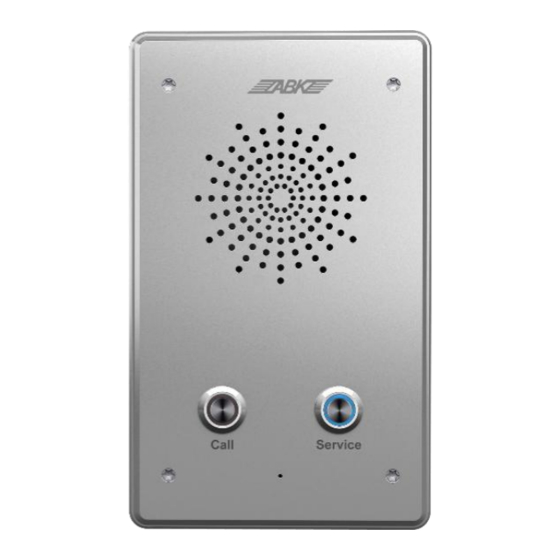
It is durable and simple to install with comfortable buttons, generous appearance and low power consumption. 1.1 Appearance Description Speaker Call button Service button (Editable) AXT8921A AXT8921B Button Description Button Description Function The shortcut button It can be set to various functions to meet the can be edited. - Page 7 Built-in 2 short-circuit inputs. Built-in 2 short-circuit outputs. 4 controlled methods: remote DTMF, remote service command, short-circuit input linkage and call status. External active speaker output interface. Support POE power supply. With multicast function. Three functions in one: intercom, broadcast and smart security. ...
-
Page 8: Operating Instructions
II. Operating Instructions Before you start to use the device, please make the following installation. 2.1 Connect the Power Supply and the Network Note! As this device can support POE power supply, please connect it via a router with POE power supply. -
Page 9: Interface Description
Interface Description a. Connection Diagram of Network PA Intercom... - Page 10 b. Connection Diagram of Peripherals c. Main Board Interface 8: MIC 9: LINE 1: WAN 2: LAN 10: LINE 7: IP PA 11: 12V Button 3: 2 Short Circuit IN 6: Restore Button 12: Built-in 4: 2 Short Speaker Circuit 5: 2 Call Buttons...
- Page 11 Interface Description Functions 10/100 adaptive Ethernet port to connect the network. With WAN port PoE power supply (It is required to connect a router with POE. Support IEEE802.3 af& at mode). 10/100 adaptive Ethernet port to connect the camera module. LAN port (Without POE power supply) Short-circuit...
- Page 12 2-channel Short-circuit OUT ON: Disconnected in idle state (normally open). OFF: Connected in idle state (normally closed). COM: Contact of the relay. 4: 2-channel Short-circuit OUT OUT2 OUT1 OFF2 COM2 OFF1 COM1 Normally Common Normally Normally Common Normally 12V Power...
- Page 13 Audio OUT...
-
Page 14: Basic Operations
III. Basic Operations 3.1 Answer a Call When there is an incoming call, the device will automatically answer the call by default. After canceling the automatic answering and setting the automatic answering time, it will send out the ringing within the set time and automatically answer the call after the timeout. -
Page 15: Page Settings
IV. Page Settings 4.1 Browser Configuration Make the device and your computer in the same LAN, enter the default IP address of the device “192.168.10.128” on the browser to open the login interface, and then enter the user name: admin, and password: admin, and finally click Login to log in to the management interface of the device. - Page 16 Network Settings Field Name Description Display the current WAN settings of the device: including WAN IP acquisition modes (Static, DHCP, PPPoE), MAC address, device IP, gateway IP; Display the corresponding phone number and status of the Phone Number current SIP Line 1-2 of the device. Time Settings Field Name Description...
-
Page 17: Network Settings
System Current View the current time of the system. Time Manual Time Set the time (Year, Month, Day, Hour and Minute) manually. Settings Network Settings Status Display Field Name Description Can view MAC address, IP address and gateway. Network Settings Use bridge mode (transparent mode): Bridge mode will make the NIC Bridge device no longer set the IP address for the LAN port, and the LAN... -
Page 18: Voip
Static You can choose this item. After selecting, you must fill in the static Mode IP address, subnet mask, gateway, DNS domain name, primary DNS, (Static) and backup DNS. In this mode, network-related information will be automatically DHCP Mode obtained from the DHCP server, and you do not need to manually enter these fields. - Page 19 Password Set the password of SIP registration account. Phone Set the number registered to the SIP server. If it is empty, the Number registration will not be initiated. Set the display name. This configuration parameter can be displayed on Display the called party (without naming the calling party) when being able to Name make a caller.
-
Page 20: Intercom Settings
the local domain name as the system will automatically go to the registered address and fill in domain realm. Server Name Name the server. Transmission Set the transmission protocol. The default is UDP. Protocol Intercom Settings a) Function Buttons Settings DSS Button Type Subtype None... - Page 21 account to be hung up by pressing the address of speed dial key again. the called Using the intercom mode. When party the SIP phone at the opposite end Intercom supports the intercom function, the call can be automatically answered. Multicast Button Settings ...
- Page 22 Voice Settings Field Name Description First Speech Select DSP first priority speech coding algorithm, including: G.711A/u, G.722, G.723, G.729, G.726-32. Coding Second Speech Select DSP second priority speech coding algorithm, including: G.711A/u, G.722, G.723, G.729, G.726-32. Coding Third Speech Select DSP third priority speech coding algorithm, including: G.711A/u, G.722, G.723, G.729, G.726-32.
- Page 23 Output Volume c) Feature Field Name Description Feature Do Not Disturb. Select this option, and then the device will reject any incoming calls, and the caller will prompt that the device is unavailable; however, outgoing calls from the machine will not be affected. Outgoing call is forbidden.
- Page 24 Time set time. Enable Speed Dial Set to enable/disable the Speed Dial key to hang up the call. It Hand-up is enabled by default. Function Set whether to enable function key answer. It is enabled by Answer default. d) Multicast The multicast function can be used to send announcements to multicast members simply and conveniently.
-
Page 25: Security Settings
Enable Page Priority: Page priority determines how to handle newly received multicast RTP streams during a multicast calling. If the page priority is enabled, the device will automatically ignore multicast RTP streams with low priority and receive multicast RTP streams with higher priority, and leave the current multicast calling in the hold state;... - Page 26 When high level trigger (disconnect trigger) is selected, it will trigger when it detects that the input port 1 is (in high level) disconnected. Output Settings (Same as OUT2) OUT1/2 Set to turn on/off the output port 1/2. When low level (NO terminal: normally open) is selected, the NO terminal is triggered to disconnect when the trigger conditions are Output met.
-
Page 27: Management Settings
Management Settings a) User Settings Field Name Description User Information Change User Name Set the user name to be added. Password Set the password of the account to be added Password Second confirmation of the password to ensure that the password is Confirm set correctly. - Page 28 c) Language Settings Select the language to be displayed through this settings. d) System Upgrade Field Name Description System Version V1.0.0 Display the software version. Webpage Update Select File Select the upgrade file and select update.
-
Page 29: Video (Only For Video Intercom Terminal)
e) File Information Configuration Clear configuration files and restore factory settings. Video (Only for Video Intercom Terminal) Can set the parameters of the video settings. - Page 30 Field Name Description Video Resolution Optional video resolution: 720P and 1080P. Frame Rate Optional video frame rate among 1-20. Bit Rate Control Bit rates: CBR(Constant Bit Rate) and VBR(Variable Bit Rate). Image Quality Select the video image quality. Bit Rate Value Optional bit rate values.
- Page 31 V. Functions WAN port: 10/100 adaptive Ethernet port to connect the network, which can be powered by PoE (need to connect a router with POE function to support IEEE802.3 af&at mode). LAN port: 10/100 adaptive Ethernet port to expand the interface (only for AXT8921). Short-circuit input monitoring interface: Two groups of short-circuit input detection, which can be used to connect input devices such as door sensor and vibration sensor.
- Page 32 12V DC interface: 12V DC power interface. Built-in speaker interface: Connect the built-in speaker (4Ω 2W). Terminal Function Table Item Function & Symbol Name NET IN RJ45 Extended Port (Only for RJ45 AXT8921) STC1 Input Signal 1 SC IN DC Input Signal Ground DC Input Signal Ground STC2 Input Signal 2...
- Page 33 (It is recommended to adopt vertical installation, as shown below) Bottom Case Installation Dimensions: Unit: mm AXT8921A/AXT8921B Bottom Case...
- Page 34 Panel Installation Dimensions: Unit: mm AXT8921A/AXT8921B Panel...
-
Page 35: Appendix
VII. Appendix 7.1 Technical Parameters Model AXT8921A AXT8921B Communication Protocol SIP 2.0(RFC-3261) Supported Protocols CODEC G.729, G.723, G.711, G.722, G.726 Voice Audio Amplifier 2.4W Streaming Volume Control Adjustable Full Duplex Hands-free Support (AEC) DSS Button 1 or 2 (PH2.0 pin) 1 (XH2.54 pin)
Need help?
Do you have a question about the AXT8921A and is the answer not in the manual?
Questions and answers