Table of Contents
Advertisement
Quick Links
Operating Instructions
Ultrasonic Industrial Sensor USi
Master
USi-PP
1005632 *
USi-IP
1005899 *
USi-UP
1005901 *
* plus Sensor 1005264
Original instructions
Slave
1005633 *
100900 *
1005902 *
Polymer Electric
GmbH & Co. KG
Polymer Electric
Örlinger Straße 1–3
89073 Ulm
GERMANY
Tel.: +49 731 2061-0
Fax: +49 731 2061-222
E-Mail: info.ulm@mayser.com
Internet: www.mayser.com
Version 03
Advertisement
Table of Contents

Summary of Contents for MAYSER USi-PP
- Page 1 Polymer Electric Operating Instructions Ultrasonic Industrial Sensor USi Version 03 GmbH & Co. KG Master Slave Polymer Electric USi-PP 1005632 * 1005633 * Örlinger Straße 1–3 USi-IP 1005899 * 100900 * 89073 Ulm USi-UP 1005901 * 1005902 * GERMANY * plus Sensor 1005264 Tel.: +49 731 2061-0...
-
Page 2: Table Of Contents
Offenders will be held liable for the payment of damages. All rights reser- ved in the event of the grant of a patent, utility model or design. © Mayser Ulm 2014 Page 2/43 Operating Instructions USi... -
Page 3: About These Operating Instructions
About these operating instructions These operating instructions are part of the product. Mayser Polymer Electric accepts no responsibility or warranty claims for damage and consequential damage due to failure to observe the operating instructions. Read operating instructions carefully before use. - Page 4 Polymer Electric About these Operating Instructions Symbol Meaning Symbols used Action with one step or with more than one step where the order is not relevant. 1..Action with more than one step where the order is rel- evant. 2.
-
Page 5: Intended Use
Polymer Electric Intended use Intended use The ultrasonic industrial sensor USi is designed for industrial use in the medium air. It is comprised of the Evaluation Unit and up to 2 sensors (ultrasonic transducers). It can be used to achieve the following functions: Reflex switch Reflex barrier Sonic barrier... -
Page 6: Applicable Standards
Polymer Electric Safety instructions Do not alter special cable The special cable on the sensor (ultrasonic transducer) has a fixed length. Never shorten, lengthen or alter the special cable. Observe PIN assignment Observe the PIN assignment when connecting the supply voltage. Do not overload Evaluation Unit Ensure that the specified switching current is not exceeded. -
Page 7: Parts Supplied
Polymer Electric Parts supplied Parts supplied 1× Evaluation Unit Enclosure with electronics module. 1× Sensor (ultrasonic transducer) 1× Operating Instructions 1× Declaration of conformity Check the scope of supply for completeness and the perfect condition of the pro- duct immediately after receipt. Required accessories: 1×... -
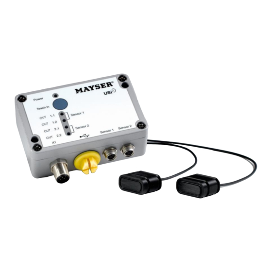
Page 8: Product Overview
Polymer Electric Product overview Product overview Sensor (Ultrasonic Transducer) The special cable between the ultrasonic transducer and the M8 plug has a fixed length of 1.5 m and may not be lengthened or shortened. Should the 1.5 m not be sufficient, the cable length can be doubled using the optional extension cable (1005903). -
Page 9: Leds Information
Polymer Electric Product overview LEDs information Green LED “Power”: supply voltage connected Yellow LED “OUT 1.1”: Output 1.1 activated Yellow LED “OUT 1.2”: Output 1.2 activated Yellow LED “OUT 2.1”: Output 2.1 activated Yellow LED “OUT 2.2”: Output 2.2 activated Connections M8 socket: Sensor 2 Screw plug: Mini USB... -
Page 10: Unit Cable With M12 Socket (Optional)
Polymer Electric Product overview Unit Cable with M12 Socket (optional) Cable for connection to downstream control system. The Type LifYCY unit cable must be 8-poled (each lead min. 0.25 mm ), shielded and equipped with an M12 socket. Maximum length of the unit cable: 30 m. Signal Lead colour Supply voltage... - Page 11 Polymer Electric Product overview Opening angle (-6 dB) narrow side Reference axis Opening angle (-6 dB) broad side Reference axis Sonic lobe spatially 281114 v1.3 Operating Instructions USi Page 11/43...
-
Page 12: Operation
(preset as normally open contacts) “OUT X.1” and “OUT X.2” are closed. Operating Mode 2 Ranges If switch point SP1 selection is larger than 1 cm, the USi-PP automatically changes to operating mode 2 ranges. SP1: > 1 cm SP2: >... -
Page 13: Operating Mode Window
Polymer Electric Operation Operating Mode Window The operating mode Window can be exclusively selected via the parameter assign- ment software (optional). SP1: > 1 cm SP2: > (SP1 + 1 cm) In contrast to operating mode 2 ranges, here the detection field that is sensor- proximal will not be visible. -
Page 14: Operating Mode Window
Polymer Electric Operation USi-IP The distances determined by the sensor are indicated as analog current values between 4.8 and 20 mA on output “OUT°1.1” . The linear progression results from the even sub-division of the total measurement distance up to SP2. In the default set- ting, this is 0.08 mA per centimetre. -
Page 15: Examples Of Use
Polymer Electric Installation Examples of Use Object detection 1. Simplest function: Is an object loca- 1. Operating mode 1 range. ted in the free detection field? 2. Presence / absence monitoring: Does 2. Operating mode 1 range and the taught-in environment change? teach in. - Page 16 Polymer Electric Installation Obstacle detection 11. Path check: Is the path taken unob- 11. Operating mode 1 range. structed? 12. Distance check: When is a defined 12. Operating mode 2 ranges and distance to the obstacle fall so far short specification of the switch points SP1 (SP1) that action must be taken? and SP2.
-
Page 17: Installation
Polymer Electric Installation Installation The installation includes three individual installation steps: 1. Mounting the sensor (ultrasonic transducer) 2. Mounting the Evaluation Unit 3. Wiring the unit cable Mounting the Sensor (Ultrasonic Transducer) The sensors can be mounted in any position. If the sensors are supposed to be mounted in quiet workplaces or in areas where there are hearing-sensitive animals, the interfering sonification must be considered. -
Page 18: Alternative: Enclosure Set (Optional)
Repairs are not possible. Alternative: Enclosure set (optional) Instead of using your own brackets you can also use one of the Mayser enclosure sets. See Chapter Accessories for a small selection. The installation steps are the same as described above. -
Page 19: Alternative: Mounting Rail Adapter (Optional)
Disconnect all devices and live parts in the immediate environment of the power supply and protect them against being switched on again (see relevant Operating Instructions). Check whether all devices and parts are disconnected from the power supply. Lead colour Signal USi-PP USi-IP USi-UP Brown DC 15 to 30 V Blue max. - Page 20 Polymer Electric Installation CAUTION Failure due to incorrect wiring! Carefully check the wiring. Inspect the supply voltage. Impaired operation due to missing grounding! CAUTION Carefully check the grounding Page 20/43 Operating Instructions USi 281114 v1.3...
-
Page 21: Commissioning
Polymer Electric Commissioning Commissioning The Evaluation Unit expects that at least one sensor (ultrasonic transducer) is con- nected. If only one sensor (ultrasonic transducer) is used, then this must be con- nected to “Sensor 1” . 1. Connect the sensor (ultrasonic transducer) and the unit cable with the Evaluati- on Unit. -
Page 22: Testing The Function
Green LED “Power” is lit Yellow LEDs “OUT 1” and “OUT 1.2” are lit USi-PP: Outputs 1.1 and 1.2 are closed USi-IP/UP: analog Signal at output 1.1, output 1.2 is closed Yellow LEDs “OUT 2” and “OUT 2.2” are off Outputs 2.1 and 2.2 are open... -
Page 23: Adjust Settings
Polymer Electric Adjust settings Adjust Settings The following settings can be changed with the “Teach In” button: 1. Teach in environment 2. Adjusting switch points 3. Logoff/logon sensor 4. Restore factory settings Teach In: Teach in Environment The actual function of “Teach In” is to teach in the environment within the detection field. - Page 24 Polymer Electric Adjust settings The switch points can be set between 1 and 250 cm. The “Set Switch Points” function is always available with a USi that is ready for operation. The preset standard settings for all sensors are switch points SP1 = 1 cm and SP2 = 200 cm.
-
Page 25: Logon/Logoff Sensor 2
Polymer Electric Adjust settings 8. Place the reference object at the desired distance in the detection field. If the USi recognises the reference object, the green LED “Power” changes from quick flashing (5 Hz) to being continuously lit. 9. Press the “Teach In” button (> 0.5 s), and the USi overwrites the previous switch point SP1 with the determined distance to the reference object. -
Page 26: Restore Factory Settings
Polymer Electric Adjust settings 6. Now press the “Teach In” button > 0.5 s. The USi signalises that Sensor 2 is now logged on by the continuously lit yellow LEDs “OUT” for 1 s. This is how to logoff Sensor 2: 1. - Page 27 Polymer Electric Adjust settings The green LED “Power” flashes for 5 s slowly (1 Hz), then the yellow LEDs “OUT” are lit continuously for 2 s. Subsequently, the green LED “Power” flashes slowly (1 Hz). 4. Now release the “Teach In” button. Now all the LEDs are lit alternately from the top to the bottom in the manner of a chaser light.
-
Page 28: Troubleshooting And Remedies
Polymer Electric Troubleshooting and remedies Troubleshooting and remedies Prerequisite: The USi is connected to the supply voltage. There is at least one sensor connected to the Evaluation Unit. Only taught-in objects are located in the detection field. For troubleshooting upon initialisation see Chapter Commissioning / Connections. Fault display Possible cause Elimination... - Page 29 Polymer Electric Troubleshooting and remedies Fault display Possible cause Elimination Yellow LED “OUT X.X” Taught-in detection field has changed Press the “Teach In” button until the (normally open contact) green LED “Power” flashes (see chap- is lit, although there is ter Teach In: Teach In Environment) no variable object in the detection field...
- Page 30 Too extreme temperature fluctuations wi- Give the USi sufficient time (> 10 min) thin too short a time period to acclimatise. Fault can still not be detected? Contact Mayser-Support: Tel. +49 731 2061-0. Page 30/43 Operating Instructions USi 281114 v1.3...
-
Page 31: Replacement Parts
1.5 m cable Malfunction due to spare parts from third-party suppliers CAUTION Malfunctions can occur if product parts are not replaced with original parts from Mayser. Only use original parts from Mayser. Accessories Designation Part number O-Ring Set 18×2.5 mm for... - Page 32 1× on USB flash drive Malfunction due to spare parts from third-party suppliers CAUTION Malfunctions can occur if third-party replacement parts are installed instead of original parts from Mayser. Only use original parts from Mayser. Page 32/43 Operating Instructions USi 281114 v1.3...
-
Page 33: Maintenance And Cleaning
Polymer Electric Maintenance and cleaning Maintenance and cleaning Maintenance The USi is maintenance-free. Repeat the functional test annually. For harsh environmental conditions or very high detection frequency, the interval for the functional test is reduced accordingly. Cleaning Danger of injury due to electrocution! WARNING Disconnect the USi as well as all devices and live parts in the immediate environment from the power supply and protect them against being switched... -
Page 34: Decommissioning
2. Disconnect the wiring. Disposal The Control Units produced by Mayser are professional electronic tools exclusively intended for commercial use (so-called B2B devices). Unlike devices mainly used in private households (B2C), they may not be disposed of at the collection centres of public sector disposal organisations (e.g. -
Page 35: Conformity
2004/108/EC (EMC) The Declaration of Conformity is available in the Downloads section of our website: www.mayser-sicherheitstechnik.de Factory Settings The USi is returned to the condition supplied to the customer by performing RESET. The factory settings stored in the USi thereby overwrite all current parameters. -
Page 36: Technical Data
The “type” information refers to the USi in the condition supplied to the customer. If parameters are changed, these values change. The thereby potential bandwidth will be indicated by “ . .. to ...” . USi-PP/ USi-IP/ USi-UP Testing basis IEC 60947-5-2, IEC 60204-1... - Page 37 Polymer Electric Technical data USi-PP/ USi-IP/ USi-UP Inputs Sensor 1 and 2 Sensor 1 and Sensor 2 Connection M8, 3-pole Line length 1.5 m (+1.5 m extension cable) USB Mini-B Version Type Outputs Type: short-circuit-proof NO contact, NC contact, off Output 1.1 (OUT 1.1)
-
Page 38: Glossary
Coverage range Range, where the switch points can be set. [IEC 60947-5-2, 2.3.1.2] Condition as supplied Condition of the USi upon leaving Mayser. All parameters conform to the factory settings. Detection Basic function of a proximity switch. In contrast to the basic function measurement, the objective of the evaluation of the echo signals is only to determine the two con- ditions “object present”... - Page 39 Polymer Electric Glossary Factory setting Table of all USi parameters, which are permanently saved in the USi and replace all changed USi parameters when RESET. In the condition as supplied to customer all USi parameters conform to the factory settings. Initialisation Start sequence of the USi as soon as the supply voltage is connected.
- Page 40 Output Connection on which the output signal of a proximity switch is connected. The USi-PP has 4 digital outputs, 2 each for every sensor (Sensor 1, Sensor 2). USi-IP and USi-UP each have 3 digital outputs and one analog output (cf. Output...
- Page 41 Polymer Electric Glossary is connected. The analog output OUT°1.1 can also be assigned an inverted output signal via the parameter assignment software (optional). (cf. Output, OUT) Output digital Semi-conductor of type PNP. Each output can be an NO contact, an NC contact or Off.
- Page 42 Polymer Electric Glossary Slave That USi of a multisensor, which receives the synchronisation signal SYNC from the master. Formula for the minimum switching distance. Sensor Proximity switch, which operates in the basic function measurement. Here, the objective of the evaluation of the echo signals is to determine the distance of the detected objects.
- Page 43 Sensor, Transducer) Abbreviation for Ultrasonic Industrial Sensor. USi-IP Abbreviation for USi with one power output and three PNP outputs. USi-PP Abbreviation for USi with two PNP outputs per sensor. USi-UP Abbreviation for USi with one voltage output and three PNP outputs.
Need help?
Do you have a question about the USi-PP and is the answer not in the manual?
Questions and answers