Table of Contents
Advertisement
Quick Links
TABLE OF CONTENTS
1 Warning -------------------------------------------------------------- 2
2 Specifications ----------------------------------------------------- 2
3 Troubleshooting Guide ----------------------------------------- 3
4 Disassembly and Assembly Instructions ---------------- 4
4.1. Disassembly Instructions -------------------------------- 4
4.2. Assembly Instructions ------------------------------------ 6
5 Wiring Connection Diagram ---------------------------------- 7
6 Schematic Diagram ---------------------------------------------- 8
7 Exploded View and Replacement Parts List ------------ 9
7.1. Exploded View --------------------------------------------- 9
7.2. Replacement Parts List ---------------------------------10
Model No.
Asia
PAGE
© Panasonic Corporation, 2013.
Unauthorized copying and distribution is a violation
of law.
Order Number PEWT1311A61CE
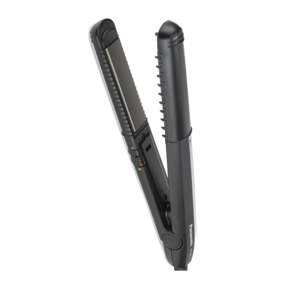
Compact Straightener
EH-HW19
PAGE
Advertisement
Table of Contents

Subscribe to Our Youtube Channel
Related Manuals for Panasonic EH-HW19


Summary of Contents for Panasonic EH-HW19
-
Page 1: Table Of Contents
5 Wiring Connection Diagram ---------------------------------- 7 6 Schematic Diagram ---------------------------------------------- 8 7 Exploded View and Replacement Parts List ------------ 9 7.1. Exploded View --------------------------------------------- 9 7.2. Replacement Parts List ---------------------------------10 © Panasonic Corporation, 2013. Unauthorized copying and distribution is a violation of law. -
Page 2: Warning
1 Warning Caution: • Pb free solder has a higher melting point that standard solder; Typically the melting point is 50 - 70°F (30 - 40°C) higher. Please use a soldering iron with temperature control and adjust it to 750 ± 20°F (400 ± 10°C). In case of using high temperature solder- ing iron, please be careful not to heat too long. -
Page 3: Troubleshooting Guide
3 Troubleshooting Guide (Refer to SCHEMATIC DIAGRAM) -
Page 4: Disassembly And Assembly Instructions
4 Disassembly and Assembly Instructions 4.1. Disassembly Instructions 1. Insert a small flat head screwdriver into the groove of the 3. Remove the spring by pull out the Housing side and Shaft Cover as shown in Figure 4. Press plate side as shown in Figure 6. (Figure 6) 4. - Page 5 6. Remove the Iron Plate ass'y B/K of Press plate side as 8. Take off the Housing B as shown in Figure 11. shown in Figure 9. (Figure 9) (Figure 11) 7. Using screwdriver remove the 2 tapping screw and 1 torx 9.
-
Page 6: Assembly Instructions
4.2. Assembly Instructions 1. Arrange Lead wire into rib of Press plate as shown in Figure 13. (Figure 13) • Arrange Lead wire into rib of Housing A as shown in Figure 14. (Figure 14) 2. Assembly Housing B together with Housing A as shown in Figure 15. •... -
Page 7: Wiring Connection Diagram
5 Wiring Connection Diagram (Figure 17) -
Page 8: Schematic Diagram
6 Schematic Diagram (Figure 18) -
Page 9: Exploded View And Replacement Parts List
7 Exploded View and Replacement Parts List 7.1. Exploded View All parts are supplied from PMFTH-AP through PLAP... -
Page 10: Replacement Parts List
EHHW19HSABW HOUSING A EHHW19IPBW IRON PLATE BLOCK OTHERS EHHW19IP41BW IRON PLATE BLOCK (FOR EH-HW19-K415 : INDONESIA) EHHW19IP66BW IRON PLATE BLOCK (FOR EH-HW19-K665 : SAUDI ARABIA) EHHW19CTBW CONNECTOR COVER BLOCK EHHW19PCB2BW POWER CORD (B2-PLUG) EHHW19PCS3BW POWER CORD (S3-PLUG) EHHW19T2608W TAPPING SCREW 2.6*8...
Need help?
Do you have a question about the EH-HW19 and is the answer not in the manual?
Questions and answers