Table of Contents
Advertisement
Quick Links
Advertisement
Chapters
Table of Contents

Related Manuals for MC3 ChipMaster

Summary of Contents for MC3 ChipMaster
- Page 1 ChipMaster Operation & Maintenance Manual...
- Page 2 ChipMaster Conveyor Operation & Maintenance Manual MC3 Manufacturing Inc. 1979 Setterington Drive, RR2 Kingsville, Ontario N9Y 2E5, Canada Phone: 519-325-1370 Fax: 519-325-1374 Email: info@mc3mfg.com Web: www.mc3mfg.com The content of this manual is owned and copyrighted by MC3 Manufacturing Inc. Rev. 05-2021...
-
Page 3: Table Of Contents
ChipMaster Conveyor Operation & Maintenance Manual Table of Contents Introduction Delivery Inspection Warranty Safety Safety Sign Off Form Installation Instructions Operating Safety Operating Instructions Maintenance Troubleshooting Replacement Parts Recommended Spare Parts Notes Rev. 05-2021... -
Page 4: Introduction
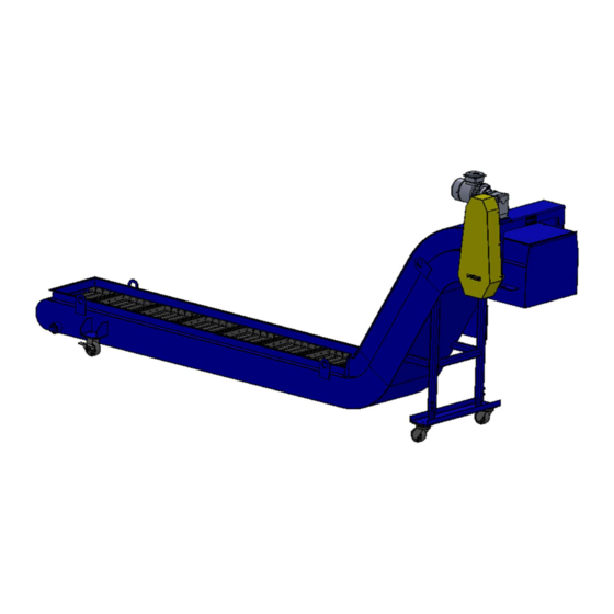
Introduction Congratulations! You have made a wise choice of Hinge Belt Conveyors. The MC3 ChipMaster Conveyor has been designed to provide you with the highest standards of quality, reliability, and durability. This manual has been prepared to familiarize you with the operation and maintenance of your ChipMaster Conveyor. -
Page 5: Delivery Inspection
Operation & Maintenance Manual Delivery Inspection Upon delivery of your ChipMaster Conveyor, check your packing slip or bill of landing accompanying the unit. Should you find any components missing, contact MC3 Manufacturing Inc. immediately with a description of the missing components and the serial number of the machine. See Fig. 1 for serial tag location. -
Page 6: Warranty
Seller warrants that the material and workmanship on the equipment manufactured by MC3 Manufacturing will be free from defects at the time of shipment. If during the first 12 months (or 2000 hours, whichever comes first) of operation after final shipment, the Buyer establishes to the Seller’s satisfaction that any part or parts manufactured by MC3... -
Page 7: Safety
ChipMaster Conveyor Operation & Maintenance Manual Safety Warning! Read and understand the operator’s manual and all other safety instructions before using this equipment. Failure to follow operating instructions could result in serious injury or death. ATTENTION: Your safety... - Page 8 ChipMaster Conveyor Operation & Maintenance Manual Safety - It’s in your interest Safety Guidelines Safe operation is one of our main concerns. However, it is up to the operator to practice caution and maintain safe operating procedures. To avoid personal injury, study the following precautions and insist that those working with you follow them.
- Page 9 ChipMaster Conveyor Operation & Maintenance Manual Installation Safety Wear safety glasses, safety shoes, and gloves. Ensure area around installation site is free of debris and obstructions. Be aware of any sharp edges while handling conveyor components. ...
- Page 10 Operation & Maintenance Manual Sign Off Form MC3 Manufacturing Inc. follows the general Safety Standards specified by the Occupational Health and Safety Administration (OSHA). Anyone who will be operating and/or maintaining this conveyor must read and clearly understand ALL safety, operating, and maintenance instructions presented in this manual.
- Page 11 Please follow the relevant instructions below for your specific conveyor. Note: If special circumstances or questions arise, please contact MC3 Manufacturing Inc. at: (519) 325-1370 quoting the serial number of the machine. Installation Tools Following is a list of tools required to complete the installation ...
- Page 12 ChipMaster Conveyor Operation & Maintenance Manual Fully Assembled Conveyors Unpack the conveyor and check for damage Ensure the installation area is flat and free of debris Position the horizontal in-feed section as desired and ensure that it is level in both directions ...
- Page 13 ChipMaster Conveyor Operation & Maintenance Manual Conveyors are supplied with one of three leg options: o Fixed legs o Adjustable legs o Castors For fixed legs, drill through the holes in the feet and use suitable anchors to fasten the conveyor to the floor ...
- Page 14 ChipMaster Conveyor Operation & Maintenance Manual Note: On a sectional belt, all mating sections are clearly identified, and the leading section has a special pan with a welded hook attachment For belt supplied in sections, assemble as shown in Fig. 2 o Locate the mating ends of each belt section.
- Page 15 ChipMaster Conveyor Operation & Maintenance Manual o Remove the chain guard. o Loosen all the set screws in the motor drive sprocket, torque limiter, belt drive sprockets, and pillow block bearings. o Slide the belt drive sprockets off their keys and remove the keys.
- Page 16 ChipMaster Conveyor Operation & Maintenance Manual Fig. 5 Fig. 6 Fig. 7 Note: It may be necessary to reposition the winch several times, depending upon the length of the incline, size of winch, etc. See Figs 8-9. Fig. 8 Fig. 9...
- Page 17 ChipMaster Conveyor Operation & Maintenance Manual Continue to pull the belt up the incline until the upper belt extends beyond the lower belt by the width of one pan. Note: In order to pull the belt around the final bend, the winch will need to be attached to an immovable object, such as a fork lift.
- Page 18 ChipMaster Conveyor Operation & Maintenance Manual Note: It is important to ensure that the chain drive sprockets are axially aligned to prevent premature chain wear and overloading of the drive motor. Adjust the tension in the drive chain using the threaded rods under the motor mount.
- Page 19 ChipMaster Conveyor Operation & Maintenance Manual Starting the First Time Make sure area is clear of people and foreign objects. Note: Before starting the conveyor for the first time, ensure there are no foreign objects (nuts, bolts, tools etc.) on the frame or belt. The area around the conveyor should be cleared of personnel and ‘Caution’...
-
Page 20: Operating Safety
ChipMaster Conveyor Operation & Maintenance Manual TO THE NEW OPERATOR OR OWNER OPERATING SAFETY The ChipMaster Conveyor is designed to filter waste material from machining and sort scrap that accumulates from metal 1. Read and understand all of this Operator’s forming. - Page 21 ChipMaster Conveyor Operation & Maintenance Manual Operating the Conveyor NEVER operate the conveyor with guarding removed. Make sure area is clear of people and foreign objects The procedures for routine operation of the conveyor will vary depending on whether the conveyor has its own control system or if it is tied into your machine control system.
-
Page 22: Maintenance
ChipMaster Conveyor Operation & Maintenance Manual Routine Maintenance Disconnect power supply and lock out before removing any guards, attempting any maintenance, trouble shooting, or making adjustments. Warning! Ensure all moving parts have completely stopped before opening shields or reaching into conveyor. - Page 23 ChipMaster Conveyor Operation & Maintenance Manual Condition Lubricating Frequency Normal 8 hr Day – Light Loads 2-3 Years Heavy 24 hr Day – Heavy Loads – 1 Year Dirty Conditions Extreme – Shock Loads – High Temperature 3-9 Months Typical Lubricants Chevron Oil Co.
- Page 24 ChipMaster Conveyor Operation & Maintenance Manual Ambient Temperature 15°F to 60°F (-9°C to 16°C) 50°F to 125°F (10°C to 52°C) A.G.M.A.#7 Compound A.G.M.A.#8 Compound Mobil - Compound #DD Mobil - #600W Super Cyl. Oil Shell - Macoma Oil #69 Shell - Valvata Oil J81 & J82 Sinclair - #87 H.D.
- Page 25 ChipMaster Conveyor Operation & Maintenance Manual General Maintenance - Set up a weekly check on all bearings to ensure they remain tightly bolted down, set screws remain fastened securely, and they are correctly lubricated. Chain and Sprockets Lubrication – For long chain life, a constant film of oil is recommended. Use a good quality, non-detergent, petroleum-based oil from the list shown in Fig.
- Page 26 ChipMaster Conveyor Operation & Maintenance Manual Torque Limiter Cleaning - If, under normal loading, the torque limiter begins to slip, immediately stop and lockout the conveyor. Check the sprockets and friction faces to ensure they are free of oil, grease, moisture, or rust.
- Page 27 ChipMaster Conveyor Operation & Maintenance Manual General Maintenance Disconnect power supply and lock out before removing any guards, attempting any maintenance, trouble shooting, or making adjustments. Warning! Ensure all moving parts have completely stopped before opening shields or reaching into conveyor.
- Page 28 ChipMaster Conveyor Operation & Maintenance Manual ChipMaster Conveyor Maintenance Schedule Daily Inspection a) Check for abnormal sounds around conveyor b) Check for cleanliness c) Check that the conveyor is clear before starting Monthly Inspection a) Check belt tension b) Check belt for excessive wear...
-
Page 29: Troubleshooting
ChipMaster Conveyor Operation & Maintenance Manual TROUBLESHOOTING Troubleshooting Rules Proper troubleshooting is finding the cause of a problem and correcting it in a safe and systematic manner. Often, the trouble-shooter’s ability to solve the problem quickly benefits the production economically. - Page 30 ChipMaster Conveyor Operation & Maintenance Manual Experience There is a way to capture a small part of the experience of personnel so those who have not seen a particular event for themselves can refer to it in the future. Conveyor history or a conveyor trouble log can tell quite a tale over the life of the conveyor.
- Page 31 ChipMaster Conveyor Operation & Maintenance Manual TROUBLESHOOTING TIPS Problem Probable Cause Remedy Main disconnect off Conveyor Problems Conveyor will not start Turn main disconnect on Conveyor will not run Blown Fuse Determine cause of blown fuse, correct problem, and install new fuse...
- Page 32 ChipMaster Conveyor Operation & Maintenance Manual Problem Probable Cause Remedy Abnormal noises Squealing Cotter pins dragging on frame Turn off conveyor, all cotter pins are fully bent Dry driveshaft bearings Lubricate bearings Clicking Loose drive chain Turn off conveyor and...
-
Page 33: Replacement Parts
Note: Please refer to following chart for part description and contact MC3 Manufacturing for specific parts numbers. Reference Serial Number (found near the drive assembly). - Page 34 ChipMaster Conveyor Operation & Maintenance Manual Item Part description Drive chain 60b10x1.125" bore sprocket Sprocket torque limiter 636, 9.022" diameter Bushing torque limiter .655" long Drive shaft Torque limiter 1.25" bore 500a2 Bearing Gear box Motor /gearbox adaptor Motor Gearbox output shaft...
-
Page 35: Notes
ChipMaster Conveyor Operation & Maintenance Manual Notes: Rev. 05-2021... - Page 36 F O R M Emerson Industrial Automation Power Transmission Solutions TORQUE LIMITER 4446-004 7120 New Buffington Road Florence, KY 41042 INSTALLATION & MAINTENANCE Revised Application Engineering: 800 626 2093 November 2009 INSTRUCTIONS FOR 250A THRU 700A www.emerson-ept.com • Read and follow all instructions carefully. • Periodic inspections should be performed. Failure to perform proper maintenance can result in premature product failure and personal injury. • Disconnect and lock-out power before installation and maintenance. Working on or near energized equipment can result in severe injury or death. • All electrical work should be performed by qualified personnel and compliant with local and national electrical codes. • Do not operate equipment without guards in place. Exposed equipment can result in severe injury or death. GENERAL Before assembly, the pressure plates, facings and center member (sprocket, sheave, plate, etc.) should be free of oil, grease, dirt and rust. The center member should have a 125 micro-inch finish in the bore and a 63 micro-inch finish on the area where the friction...
- Page 37 (B) For the 500A and 700A models: THIS ADDITIONAL STEP IS APPLICABLE TO THE TORQUE LIMITER COUPLING ONLY: Maximum Rated Torque (a) Never use a torque limiter alone as a coupling. With the 3 cap screws backed out until the points are When shaft coupling is required in conjuction with slip below the surface of the nut, run the nut up finger tight protection, use a torque limiter coupling. or slightly less than finger tight, and alternately tighten the cap screws no more than turn at a time until (b) After setting torque limiter per steps 4 and 5 above their heads bottom. Do not overtighten the cap screws (with flat sprocket installed as the center member in nor completely flatten the disk spring. This should give torque limiter), mount it on the shaft. Then mount the the maximum rated torque, but since there are several coupling half (the sprocket with the hub) onto the shaft variables that affect the setting, it should be checked per to be coupled, leaving a gap between adjacent sprocket...
- Page 38 Betriebs- und Wartungsanleitung B 1033 Operating and Maintenance Instruction 11/2005 GB FR Notice de mise en service et d’entretien UNIVERSAL – Schneckengetriebe, Typ SD / SI UNIVERSAL – Worm Gear Units, Typ SD / SI UNIVERSAL – Réducteurs à roue et vis sans fin, Typ SD / SI Diese Sicherheitshinweise sind aufzubewahren These safety instructions must be kept available...
- Page 39 Δ Warnung Δ Caution Δ Avertissement wird vorausgesetzt, daß It is presumed that fundamental project work Il est impératif que les travaux fondamentaux as well as all work with regard to transport, grundsätzlichen Planungsarbeiten der Anlage de l'installation, ainsi que tous les travaux de sowie Transport, Montage,...
- Page 40 Wartung Maintenance Entretien GETRIEBE/MOTOR GEARBOX/MOTOR DU REDUCTEUR/ DU MOTEUR Die UNIVERSAL-Schneckengetriebe sind UNIVERSAL series worm- Les réducteurs et les motoréducteurs à mit synthetischem Öl befüllt, dadurch ist gearboxes are filled with synthetic roue et vis sans fin UNIVERSAL sont über die gesamte Lebensdauer eine lubricant/bearing-grease.
- Page 41 www.nord.com...
- Page 42 BIM 1004 MOTORS AC Induction, Single and Polyphase Installation and Maintenance Instructions Copyright 2005, NORD Gear Corporation All rights reserved. No part of this book covered by the copyright hereon may be reproduced or copied in any form or by any means without the written permission of the NORD Gear Corporation. BIM 1004/2005/05 Page 1 of 20 www.nord.com...
- Page 43 NOTES BIM 1004/2005/05 Page 2 of 20 www.nord.com...
- Page 44 TABLE OF CONTENTS Subject Page Introduction..............................4 Description and Operation ..........................4 Inspection..............................6 Testing and Fault Isolation..........................7 Lubrication..............................9 Removal, Installation, and Handling......................9 Connection Diagrams..........................12 Repair................................13 Parts List ..............................14 Motor Options & Nomenclature ......................... 17 LIST OF ILLUSTRATIONS Figure No.
-
Page 45: Introduction
INTRODUCTION General This manual includes general motor description and operation, inspection, testing and fault isolation procedures and information, general lubrication instructions and materials, general installation, removal, and handling instructions, and general repair and parts information. Related Publications The related publications listed in Table 1 provide additional information to support maintenance and fault isolation of the motor and its installation. -
Page 46: Figure 1 Motor Nameplates
Figure 1. Motor Nameplates Field Definition Field Definition Type Model Number Drip Proof 3~ph.M. Number of Motor Phases Ins. Cl Insulation Class Motor Number SER. F Service Factor (allowable horsepower loading) Duty Cycle (i.e. S1, S3-40%) Encl. Enclosure Description Frame Motor Frame Size Code NEMA Code Letter... -
Page 47: Inspection
INSPECTION Inspection Interval Inspect the motor after every 500 operating hours. Inspection Criteria Inspect the motor according to the criteria in Table 3. CAUTION: IF IT IS NECESSARY TO CLEAN THE MOTOR EXTERIOR, DO NOT USE SHOP AIR. SHOP AIR CAN FORCE CONTAMINANTS INTO THE MOTOR, AND CAN CAUSE THE BLOWN CONTAMINANTS TO AFFECT OTHER COMPONENTS. -
Page 48: Testing And Fault Isolation
TESTING AND FAULT ISOLATION General NOTE: NORD electric motors do not require periodic testing. However, if a motor is removed from its installation, NORD recommends that the motor be checked according to the static and dynamic testing provided below before it is reinstalled. Finding a condition that will require future repair before the motor is reinstalled decreases the overall maintenance time. -
Page 49: Table 4 Motor Fault Isolation
Fault Isolation If the motor has failed or does not meet the requirements of any of the tests described above, use the fault isolation procedures provided in Table 4, Motor Fault Isolation. The table is based on the assumption that the motor has been operating correctly, and that a problem has occurred. -
Page 50: Lubrication
LUBRICATION General NORD motor frame sizes 63 up to and including 225 are prelubricated, therefor require no lubrication during normal operation. Frame sizes 250 and larger will have grease fittings for regreasing the motor bearings. Relubricate bearings every six months (more often if conditions require) using a polyurea base grease, No. 2 consistency & stabilized against oxidation. - Page 51 Installation with NEMA and IEC Flanges Refer to NORD Gearbox Inputs Installation and Maintenance Instructions in BIM1009. Make sure the flanges are clean and free of gasket material. Install a new gasket between the mating flanges, if applicable. Carefully move the motor to insert the motor shaft and its hub/sheave into the adapter spline, making sure the shaft key enters the mating keyway.
- Page 52 Clean all contamination and corrosion from the mating flanges. Support the motor and mount it to the adapter. Apply a medium strength thread locking compound such as blue Loctite to the bolt threads according to the instructions. Install the bolts and tighten them securely. Reconnect the wiring to the motor.
-
Page 53: Connection Diagrams
CONNECTION DIAGRAMS NEMA NEMA NEMA 3-phase motor 3-phase motor high voltage 3-phase motor V1 T2 U1 T1 W1 T3 V2 T5 V5 T8 U2 T4 U5 T7 W2 T6 W5 T9 High Voltage high voltage low voltage V1 T2 U1 T1 W1 T3 V5 T8 V2 T5... -
Page 54: Repair
REPAIR General These instructions can be generally applied to NORD motor applications. The exploded view provided in the PARTS INFORMATION section shows the parts orientation for NORD motors. To procure replacement parts from NORD, contact NORD’s customer service department (refer to INTRODUCTION). -
Page 55: Parts List
PARTS LIST General Refer to Figure 4 for parts information. If you are ordering a part, provide the model and serial number of your motor. This will determine the part number you need. Part Number Part Description Qty per Assembly Rotor Assembly A-Endbell Oil Seal... -
Page 56: Figure 3 General Motor Exploded View And Generic Parts List (2
Figure 3. General Motor Exploded View and Generic Parts List (Sheet 1 of 2) BIM 1004/2005/05 Page 15 of 20 www.nord.com... - Page 57 Figure 3. General Motor Exploded View and Generic Parts List (Sheet 2 of 2) BIM 1004/2005/05 Page 16 of 20 www.nord.com...
-
Page 58: Motor Options & Nomenclature
MOTOR OPTIONS & NOMENCLATURE General NORD offers many options for its motors. The option code will be shown in the motor nomenclature. Below are the available options Code Description Code Description With Brake TENV Motor – Without Fan Brake – Corrosion Protected OL/H TENV Motor - Without Fan &... -
Page 59: Table 6 Space Heater Data
Thermostats (Option TW) • Connection Diagram shown on Page 12 • Three temperature sensitive, bimetallic switches with normally closed contacts wired in series • One switch on each phase of the stator winding • The leads will be labeled P1 and P2 in the terminal box All wiring must be done by qualified personnel and adhere to all local codes. -
Page 60: Table 7 Encoder Wiring Designations
Encoder (Option IG) • Standard encoder manufacturer is Heidenhain (www.heidenhain.com) • All encoders will be enclosed inside the fan shroud • Incremental, Quadrature, Differential, Marker Channel • IP 64 Protection • IG1 = 1024PPR, IG2 = 2048PPR, IG4 = 4096PPR •... -
Page 61: Table 8 Blower Cooling Fan Data
BLOWER COOLING FAN (Option F & FC) • Connection Diagram shown on Page 12 • Option FC is 1 phase 115V only • Option F has capability of 1 phase or 3 phase by connecting a supplied capacitor 60 Hz Ratings 50 Hz Ratings Motor Frame Voltage [V]... - Page 62 -NOTES-...
- Page 63 -NOTES-...
Need help?
Do you have a question about the ChipMaster and is the answer not in the manual?
Questions and answers