Table of Contents
Advertisement
Quick Links
Advertisement
Table of Contents

Summary of Contents for triOS TriBox3
- Page 1 TriBox3 OPERATING INSTRUCTIONS...
-
Page 3: Table Of Contents
TABLE OF CONTENTS Product Chapter Table of Contents 5 Advanced Use 5.1 Data Export 1 General Information 5.2 Analog Output 1.1 Introduction 5.3 Relay and Buzzer 1.2 Health and Safety Information 5.4 Modbus RTU 1.3 Warnings 5.5 Network 1.4 User- and Operating Requirements 5.6 External Trigger 1.5 Intended Use 6 Malfunction and Maintenance... -
Page 4: General Information
In this manual, you will find all the information you need to commission and use the TriBox3. You can find the technical specifications and the dimensions in Chapter 7. -
Page 5: Health And Safety Information
Devices that radiate strong electromagnetic waves can influence the measurement data or result in a malfunc- tion of the sensor. Avoid using the following devices in the same room as the TriOS sensors: mobile phones, cordless phones, transmitters/ receivers and other electrical devices that produce electromagnetic waves. -
Page 6: Warnings
Make sure that the mains power cable is not run near hot surfaces. • If the cable is damaged, it must be replaced with an original part by the customer service of TriOS Mess- und Datentechnik GmbH. •... -
Page 7: Disposal Information
This product meets all the requirements of the harmonized European standards. It therefore meets the legal requirements of the EU guidelines. TriOS Mess- und Datentechnik GmbH confirms the successful testing of the product by affixing the CE marking (see annex). -
Page 8: Introduction
2.1 Product Identification The TriBox3 is available in three versions: with 4-digit serial number with and without WiFi and with 8-digit serial number, especially for the EGC Water Analyzer. There is a rating plate on the product with the following information that you can use to uniquely identify the... -
Page 9: Scope Of Delivery
TriBox3 Introduction In addition to the product bar code, the rating plate includes the TriOS Mess- und Datentechnik GmbH logo and quality label. Please note that the specifications given here are for illustration purposes only and may deviate depending on the version of the product. -
Page 10: Control Elements
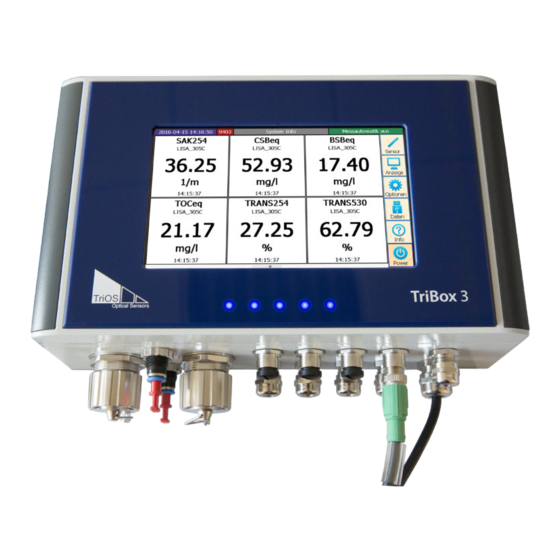
2.4.1 Display The TriBox3 has a capacitive touch-display with a resolution of 800x480 pixels. The display is not controlled by pressure, rather by touch or light tapping. It can be operated with bare fingers or with a special touch pen. -
Page 11: Commissioning
1A, 125 V, fast-blow, SMD without holder; item no. 00P100007 The TriBox3 requires a secure power supply within the voltage range of 100 VAC to 240 VAC with a mains frequency of 50 Hz to 60 Hz. The power supply must be secured according to the local safety standards. -
Page 12: Outputs
3.3 Outputs The TriBox3 has six analog outputs. The four cable glands at the bottom left of the image are not normally assigned, whereas the lower right cable bushing is intended for the mains power cable and therefore also has a larger cross section. -
Page 13: Sensor
3.4.2 Sensor The “Sensor” button opens a submenu that displays the four COM ports, with sensors if applica- ble. If there are no sensors connected or if they are not recognized by the TriBox3, the “Sensor” submenu displays the following: If a sensor is connected and is not shown on a COM port, a device search of all COM ports is initiated by press- ing on the “Scan for Sensors”... - Page 14 Change the position of a selected display in the entire order. “Sample values” is already available when commissioning the device. Create new display. 1. Select a page layout from the options displayed. 2. Click on any field of the selected page layout. D01-051en202111 Manual TriBox3...
- Page 15 (scaled value) time variation curve representation of the measurement value over time spectrum for spectral probes, representation of the measurement value over the wavelength 4. Select the sensor and the parameter and confirm by clicking “OK”. D01-051en202111 Manual TriBox3...
-
Page 16: Options
Service Mode By pressing the “Service mode” button, the TriBox3 can be put into a paused state. As long as the service mode is active, all measured values and analog outputs are held at the last measured value to avoid malfunction alarms when cleaning, etc. - Page 17 The power on the COM port can also be switched off after each measurement to save energy and individual measurements can be triggered. If this function is activated, the middle LED in the sensor power supply lights D01-051en202111 Manual TriBox3...
- Page 18 The subitem “Analog outputs” is dealt with in chapter 5.2. Modbus server settings The TCP/IP port and the slave address of the Tribox can be changed under “Modbus server settings”. Detailed information on the use of the Modbus server mode can be found in chapter 5.4. D01-051en202111 Manual TriBox3...
-
Page 19: Data
The “Info” button opens a window with system information, messages and the contact data of the nearest contact in case of problems or general inquiries. Before contacting the contact person, please read chapter 6 to ensure you have the right information for efficient troubleshooting. D01-051en202111 Manual TriBox3... -
Page 20: Power And Home
3.4.7 Power and Home The “Power” button opens a window to restart the TriBox3 or switch off the display (e.g. to save energy in an autonomous measuring station). When the display is off, you can turn it back on by touching the screen again. -
Page 21: Use
TriBox3 4 Use The TriBox3 is enclosed in a solid aluminium housing and is designed for outdoor use. The design of the TriBox3 meets the requirements of the IP65 protection class. This means that the internal components are protected against dust and water jets. For optimum operation, the device should be housed in a room or should be covered by a roof to protect against rain. -
Page 22: Mounting
2. The device will be attached downward with the connection sockets. To ensure the IP protection level, all unused connections must be sealed with the plugs used by the manufacturer. 3. There are two 5.3 mm holes on each side of the TriBox3 for mounting. Make sure the TriBox3 is securely attached after installation. - Page 23 M5x25 or longer (4 pcs) free space for installation bottom TriOS offers suitable panels for mounting the TriBox3 (Art.Nr. 11A100000). Nam e: TriBox3 TriOS M ess- und Datentechnik Gm Date: 22.09.2014 Rev.: TD011 403 fon: +49 4402 / 69 67 0 - 0 ●...
- Page 24 TriBox3 The dimensions of the panel and the mounting dimensions of the TriBox3. D01-051en202111 Manual TriBox3...
-
Page 25: Electrical Installation
TriBox3 4.2 Electrical Installation The connections for the DC power supply can be found inside the TriBox3 and are only accessible when the unit is open. The next sections describe the connection of the individual components. 4.2.1 Operation with AC Voltage Plug the provided power supply cable into a Schuko socket that has been professionally installed. - Page 26 8. Reconnect the plug to the circuit board and tighten the nut of the cable bushing. 9. Check the grounding. 10. Close the housing of the TriBox3 and screw the cover back on. Attach the aluminium panels. The device can now be put back into operation.
-
Page 27: Operation With Dc Voltage
Box3 can be operated with 12–24 V (± 5%) DC voltage. Instead of the connection cable with Schuko plug, the 12–24 V DC can be directly connected to the TriBox3. When operating on 12–24 V DC power, the Schuko plug can be removed, but this is not absolutely necessary. Be sure that the DC power source can provide the necessary maximum power and has an output with low impedance. -
Page 28: Prioritized Supply Voltage
Attach the cable to the white cable-tie holder with a cable tie. Close the housing of the TriBox3 and screw the cover closed. After the aluminium panels are attached, the device can now be put into operation. -
Page 29: Connection Of The Sensors
Only original cables from TriOS Mess- und Datentechnik GmbH may be used to connect the sensors. Connect the cable of your TriOS sensor to a COM port on the TriBox3. Insert the M12 connector plug into the desired COM port and secure the connection by fastening the fitting (see the figure below). - Page 30 Flow control: None (setting locked when using Modbus protocol) Parity: None Data bits: 8 Stop bits: 1 If the sensor is correctly recognized after being connected, it appears in the overview of the COM ports, as shown in this example diagram: D01-051en202111 Manual TriBox3...
- Page 31 The menu item “Storing” is dealt with in chapter 5.1, and the “Modbus Server Settings” can be found in chapter 5.4. Further information can be found in the corresponding sensor manual if necessary. Please contact TriOS Support if any other questions come up.
- Page 32 TriBox3 The following screen (sample illustration) opens when the “Parameter” button has been clicked. On this screen, the current scaled measured value can be seen at the top left and the unscaled measured value below that. D01-051en202111 Manual TriBox3...
- Page 33 Subitem “Smoothing” is dealt with in chapter 4.3.2. Behaviour in service mode Here a standard value can be defined, which is always output in service mode (see chapters 3.4.4 and 6.2.1). Warning levels Subitem “Warning levels” is dealt with in chapter 4.3.3. D01-051en202111 Manual TriBox3...
-
Page 34: Moving Average
Measured value Mean value over 6 measurements Mean value over 24 measurements Number of measurements Daily cycle: Regular daily cycle Mean value over 6 measurements Mean value over 24 measurements Measured value 1000 Minutes (measurement every 15 minutes) D01-051en202111 Manual TriBox3... -
Page 35: Smoothing
If the parameter settings are changed, a recalculation is then carried out on the basis of the first measured value after the change. * NaN = Not a Number. Measured value Unprocessed parameter Smoothed parameter (100%) Smoothed parameter (20%) Number of measurements If the measured values are predominantly 0, a percentage smoothing is not recommended. D01-051en202111 Manual TriBox3... -
Page 36: Warning Levels
4.4 Calibration Wizard For the calibration of various sensors, the TriBox3 has a wizard that enables a completely guided calibration. To perform a calibration with the wizard, please proceed as follows: D01-051en202111 Manual TriBox3... - Page 37 1. Switch to service mode (“Options” menu “Maintenance mode” button at the bottom of the screen). As soon as the service mode is activated, the five LEDs flash. 2. In the sensor menu, select the sensor to be calibrated by touching the blue sensor button. D01-051en202111 Manual TriBox3...
- Page 38 5. The instructions of the wizard must be strictly followed, otherwise the accuracy of the measurements cannot be guaranteed after completion of the wizard. A room temperature of around 20 °C is required for precise calibration. 6. After calibration, the service mode can be exited. D01-051en202111 Manual TriBox3...
-
Page 39: Installation Of Compressed Air Flushing
USB connection 1. Connect the compressor to the compressed air inlet of the TriBox3. To do this, insert the end of the hose into the compressed air inlet of the device and check that it is firmly seated by pulling. To remove the hose, press the small blue safety ring on the compressed air inlet in the direction of the device while pulling on the hose. - Page 40 Please note that the measurement and cleaning intervals should be matched to each other to avoid suspension of measurements. If this is necessary, use the recommended settings described in the table below. Cleaning can also be triggered and defined whether the valve and the relay are activated during cleaning. D01-051en202111 Manual TriBox3...
-
Page 41: Data Storage
15 min 10 s maximum 1 day 6 hours 20 s 5 min * with 10-meter TriOS compressed air hose 4/6 mm ** depending on the type of sensor *** see chapter 3.4.4 “Options”. 4.6 Data Storage D01-051en202111 Manual TriBox3... - Page 42 An individual storage interval can be entered for the sensor, by which the number of stored measured values can be reduced without influencing the measurement interval and any associated alarm functions. This function is deactivated when the interval is set to 0 seconds. D01-051en202111 Manual TriBox3...
-
Page 43: Recovery
The recovery point can be saved locally and on a USB storage device. If a USB stick is in the TriBox3 when the “Create” button is pressed, the following window will open and the “Create” button will turn black. -
Page 44: Advanced Use
The “Data” button opens a submenu where all settings for data exchange using a USB stick (e.g. data, software, calibration files, etc.) can be configured and executed. The subitem “Export” allows data and spectra to be copied from the TriBox3 to USB sticks, and this data can then be evaluated using standard programs. -
Page 45: Analog Output
USB stick to avoid losing any data. Suitable USB sticks that do not affect the IP protection class are available as accessories from TriOS. You can find information on the subitem “Import” in chapter 13 FAQ. - Page 46 In the lower area, you can have a fixed value held for the respective interface for test purposes. The TriBox3 has six analog outputs which provide 4...20 mA to the work area. The measured values can be transmitted in freely selectable scaling via the analogue interface to other systems, for example process control systems.
- Page 47 Assignment Analog output 1 (plus) Analog output 1 (minus, GND) Analog output 2 (plus) Analog output 2 (minus, GND) Analog output 3 (plus) Analog output 3 (minus, GND) Analog output 4 (plus) Analog output 4 (minus, GND) D01-051en202111 Manual TriBox3...
-
Page 48: Relay And Buzzer
The small cable bushings are designed for sheath diameters of 3.5-7 NOTICE To connect the relay, first carry out steps 1 - 3 in chapter 4.2.1 to open the TriBox3 and insert a suitable cable into the TriBox3. Please observe the following instructions: 1. - Page 49 1. Put the plug back in the socket and tighten the cable bushing snugly but not too tightly. 2. Attach the cable to the white cable-tie holder with a cable tie. 3. Close the housing of the TriBox3 and screw the cover closed. After the aluminium panels are attached, the device can now be put into operation.
- Page 50 Advanced Use TriBox3 D01-051en202111 Manual TriBox3...
- Page 51 TriBox3 Advanced Use Clicking the checkmark in the subitem “Buzzer control” activates a routine that is configured in the subsequent points. This defines the parameter that influences the buzzer trigger and its activation and deactivation limit. D01-051en202111 Manual TriBox3...
-
Page 52: Modbus Rtu
5.4 Modbus RTU It is also possible to operate each COM port of the Tribox3 in such a way that it works in Modbus server mode. In this mode, Modbus RTU requests can be sent to the Tribox3, e.g. to read out current measured values. To activate this mode, select the “Modbus Server”... - Page 53 TriBox3 Advanced Use In contrast to a simple Modbus device, the Tribox3 responds at several slave addresses, because the connect- ed sensors are distributed over different addresses. In these settings, you can view and change the sensor addresses being used.
- Page 54 Advanced Use TriBox3 The Tribox3 also responds to Modbus TCP commands that it receives via the network at the chosen port. Port 502 is set as the default. However, you can change this port in the Tribox3 options. D01-051en202111 Manual TriBox3...
-
Page 55: Network
In the subitem “Network settings”, you can view the IP address and check whether the WiFi is turned on. The RJ45 network connection and a internal WiFi module allow the TriBox3 to connect directly to a PC or a network. - Page 56 255.0.0.0 1 class A private network • The TriBox3 IP address must be different from the IP address of the computer. If the TriBox3 is integrated into a network, it must be unique in the entire network. • If you have any problems integrating the TriBox3, please contact your system administrator.
-
Page 57: External Trigger
5.6 External Trigger The TriBox3 offers the option of using an external trigger input to start a measurement. The trigger input can be operated with a DC voltage of 12–24 VDC (± 5%). When the trigger is set off, a measurement is started for all sensors that have automatic measurement activated. -
Page 58: Malfunction And Maintenance
Regularly check all cables for mechanical damage. • Clean the TriBox3 with a soft damp cloth from time to time. Use a mild cleaning solution if necessary. 6.1.2 Manual Sensor Cleaning To prevent unwanted measurements from being taken automatically when manually cleaning the sensors and thus possibly generating false alarms, the TriBox3 should be set to service mode beforehand. -
Page 59: Checking The Analog Outputs
To make sure that the service mode does not remain active unintentionally, it is automatically deactivated after 2 hours, and before that, the TriBox3 will begin switching the buzzer on and off once a second to notify the user. To prevent, for example, unwanted measurements when manually cleaning the sensors and thus potentially generating false alarms, the TriBox3 box should be set to service mode beforehand. -
Page 60: Checking The Valve
The internal valve may only be used in unpressurized media. In the event of water NOTICE ingress through the valve, no warranty claims can be made against TriOS. 6.2.4 Checking the Relay Danger of electric shock and fire. Only qualified personnel should carry out DANGER the inspection check described in this chapter of the operating instructions. -
Page 61: Working On The Compressed Air System
Malfunction & Maintenance 6.2.5 Working on the Compressed Air System As when cleaning the sensors, the TriBox3 should be set to service mode before working on the compressed air system. To make use of an automatic cleaning interval, this must first be activated by checking the box and setting a cleaning interval. -
Page 62: Troubleshooting
TriBox3 6.3 Troubleshooting If the TriBox3 cannot be operated as described in the manual or if it displays other abnormalities, please first make sure that it is not damaged. If the possibility of damage can be excluded, it is possible that the operating system is not working properly. In this case, reboot the system. - Page 63 TriBox3 Malfunction & Maintenance Fuses F12 and F13 Fuses F4 to F11 Fuse F14 D01-051en202111 Manual TriBox3...
-
Page 64: Measuring The Output Voltage
If zero volts are displayed between pins 1 and 4, the fuse to the right of the connector must be replaced. If zero volts are displayed between pin 1 and 5, the fuse to the left of the connector must be replaced. D01-051en202111 Manual TriBox3... -
Page 65: Sensor Is Not Displayed
6.3.3 Sensor is not displayed As soon as a sensor is connected to the TriBox3, it is displayed under the corresponding COM port. If the sensor does not appear in the display even after pressing the “Scan for Sensors” button, this can have various reasons. - Page 66 Here, too, you can carry out a check of the COM port as described in Chapter 6.3.1. If the device is still not displayed after checking the points listed above, there is probably a serious problem. In this case, please contact TriOS customer support. D01-051en202111 Manual TriBox3...
-
Page 67: Calling Up The Recovery Point
When the device is reset to the factory settings, all user-specific settings are lost! To make sure that all previously entered settings are saved and updated, the controller should be restarted after every reconfiguration. After the restart, a recovery point should be stored. D01-051en202111 Manual TriBox3... -
Page 68: Modbus Server Problems
The second item in the list (illustration) is a restore point that has been saved on a USB stick and is only dis- played as long as the USB stick is inserted in the TriBox3. When “Restore” is pressed, the following window opens. -
Page 69: Support Info
If the software update comes as a zip file, first extract the contents and copy the unzipped contents of the file to the USB stick. Then insert the USB stick in the TriBox3, and all software updates that are found will be displayed. -
Page 70: Return
Caution! Return shipments without an RMA number can not be accepted and processed! In order to ship the goods undamaged, use the original packaging. If this is not on hand, make sure that safe transport is guaranteed and the sensor is safely packed using enough packing material. D01-051en202111 Manual TriBox3... -
Page 71: Technical Data
Server TCP TCP port Adjustable (default: 502) NETWORK/USB Standard Ethernet, WiFi based on IEEE 802.11b/g/n Connection 1 RJ-45 integrated WiFi antenna (for TriBox3 with WiFi) Protocol TCP/IP, Modbus TCP, VNC Web interface USB 2.0 (Host), USB-A socket ANALOG INTERFACES Analog Output 6 analogue outputs, configurable: 4...20 mA... - Page 72 Pollution level MECHANICAL SYSTEM Dimensions (width x 280 x 170 x 94 mm ~ 11” x 6.7” x 3.7” height x depth) Weight 3.7 kg ~ 8.2 lbs Materials Housing: aluminium die-cast alloy, front panel: acrylic glass (PMMA) D01-051en202111 Manual TriBox3...
-
Page 73: External Dimensions
TriBox3 Technical Data 7.2 External Dimensions D01-051en202111 Manual TriBox3... -
Page 74: Accessories
It can be mounted together with sensors to bring the measured values in connection with the position. 8.4 TAMMO / AdamE TAMMO is an expansion module for the TriBox3 that converts analogue signals to the RS-485 Modbus RTU protocol. The analogue-to-Modbus module offers a total of two current inputs, where both the parameter and the unit can be set for two parameters. -
Page 75: Warranty
• Damage due to improper handling and use of the device is not covered by the warranty. • Damage resulting from modification or unprofessional attachment of accessories by the customer is not cov- ered by the warranty. D01-051en202111 Manual TriBox3... -
Page 76: Customer Service
Customer Service TriBox3 10 Customer Service If you are having a problem with the sensor, please contact the TriOS technical support. Technical support contact: support@trios.de Telephone: +49 (0) 4402 69670 - 0 Fax: +49 (0) 4402 69670 – 20 To help us provide faster service, please send us the device ID number by email (the last four digits of the serial number consisting of letters and numbers, e.g. -
Page 77: Contact
If you have found an error or bug in one of our devices or programs, please let us know: Technical support: support@trios.de General questions / sales: sales@trios.de Website: www.trios.de TriOS Mess- und Datentechnik GmbH Bürgermeister-Brötje-Str. 25 D-26180 Rastede Germany Telephone +49 (0) 4402 69670 - 0 Fax:... -
Page 78: Keyword Index
Compressed air cleaning Info Connection of the Sensors Intended Use Contact Control Elements Copyright Customer Service Data Data Export Log to USB Data Storage Declaration of Conformity Dimensions Main Menu Display Measuring the Output Voltage Disposal Menu Modbus RTU D01-051en202111 Manual TriBox3... - Page 79 Operating requirements Options Outputs User requirements Panel dimensions Power Power Supply Product Identification Warning levels Warnings Warranty Rating plate Recovery Relay Relay control Reset Return RMA number Safety instructions Sample Scope of Delivery Sensor Sensor interfaces Service mode D01-051en202111 Manual TriBox3...
-
Page 80: Faq - Frequently Asked Questions
The enviroFlu, microFlu and RAMSES sensors 2. What do I have to take into account when using the RAMSES sensors in conjunction with the TriBox3? Before connecting the RAMSES to the TriBox3, the following files must be imported onto the TriBox3: •... - Page 81 Click on “Protocol” and select the TriOS data protocol. Now go back to the “Sensor” menu by clicking on the “Close” button (bottom right). Connect your sensor to the TriBox3 and click on the “Scan for Sensors” button (bottom centre). All con- nected sensors are now displayed.
- Page 82 5. How to get Modbus addresses and registers from the TriBox3? The TriBox3 can output Modbus TCP/IP via its Ethernet connection port or Modbus RTU via its COM ports. The following steps explain how to get the ModbusStatus.txt file from the TriBox3.
- Page 83 TriBox3 Step 2 Connect a USB stick to the TriBox3 and open the “Data” menu. On the left side is the blue Support Information button: Pressing this button opens a submenu. If you press “Execute”, a folder with the current date of the TriBox3 will be copied to your USB stick.
-
Page 84: Annex
Bürgermeister-Brötje-Str. 25 D- 26180 Rastede Konformitätserklärung Declaration of Conformity Déclaration de Conformité Die TriOS GmbH bescheinigt die Konformität für das Produkt The TriOS GmbH herewith declares conformity of the product TriOS GmbH déclare la conformité du produit TriBox3 Bezeichnung Product name... - Page 85 Modbus documentation and it is assumed that the user is basically familiar with Modbus protocols. 2. Modbus/TCP Modbus TCP can be used by any device that can establish a TCP connection to the TriBox3. By default, the TriBox receives incoming Modbus connections on the standard port 502, but the port number can be changed in the TriBox settings.
- Page 86 By default, the TriBox itself uses slave address 1. The slave address of the sensors can be set in the sensor menu. If no address has been assigned here, the TriBox3 must be restarted. To get an overview of all slave addresses to which a slave address has been assigned, the file ‘...
- Page 87 Spectral data Measurement results Depending on the sensor type, there are two different register mappings that are used here. If it is a TriOS sensor that uses registers 1000ff for its measurement results, the registers are mapped to the same registers that are used in the sensor.
- Page 88 1064 … 1383 32 * Char[20] Names of the parameters in the order of the meas- urement results 1384 … 1639 32 * Char[16] Names of the units of the parameters in the order of the measurement results D01-051en202111 Manual TriBox3...
Need help?
Do you have a question about the TriBox3 and is the answer not in the manual?
Questions and answers