Table of Contents
Advertisement
Quick Links
Advertisement
Table of Contents

Related Manuals for Nivetec UNICONT

Summary of Contents for Nivetec UNICONT
- Page 1 BKI15ATEX0013X/1 pdf4012m600p_06 1 / 24...
- Page 2 APPROVALS: INMETRO, Certificate No.: DNV 15.0064 X BKI ATEX, Certificate No.: BKI15ATEX0013 X/1 2 / 24 pdf4012m0600p_06 BKI15ATEX0013X/1...
-
Page 3: Table Of Contents
C O N T E N T S INTRODUCTION ......................................5 ORDER CODES ......................................5 TECHNICAL DATA ....................................... 6 ......................................6 ENERAL DATA ......................... 7 DDITIONAL DATA FOR EXPLOSION PROOF CERTIFIED VERSIONS 3.2.1. - Page 4 4 / 24 pdf4012m0600p_06 BKI15ATEX0013X/1...
-
Page 5: Introduction
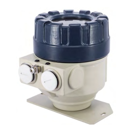
1. INTRODUCTION The UNICONT PDF-01 and PDF-01-6 / A / C Ex devices are 2-wire on-site indicators that can be inserted into a 4 – 20 mA current loop without the need for additional power supply. Since the displayed value is proportional to the input, the units are suitable for indication of temperature, pressure, level, etc. values, the information carried by the loop current. -
Page 6: Technical Data
3. TECHNICAL DATA 3.1 G ENERAL DATA PDF-01-2, PDF-401-A E PDF-01-6 E , PDF-601-A E PF-01-4, PF-401-B Ex, PF-01-8 Ex, PF-601-B Ex, PDF-401-C E PDF-601-C E PF-401-D E PF-601-D E Powering 2-wire 3-wire Input Current loop Range 3.6 – 22 mA 0 –... -
Page 7: Additional Data For Explosion - Proof Certified Versions
3.2 A DDITIONAL DATA FOR EXPLOSION PROOF CERTIFIED VERSIONS 3.2.1. ATEX A : BKI15ATEX0013 X/1 PPROVAL PDF-401-6 E PDF-401-A E PDF-401-C E Type PDF-501-6 E PDF-601-6 E PDF-601-A E PDF-601-C E Paint coated aluminium Housing PBT glass fibre reinforced Paint coated aluminium (EN AC-43100) or stainless steel (EN AC-42000) or stainless steel Ex protection Intrinsically safe... -
Page 8: Inmetro Approval
3.2.2. INMETRO A : DNV 15.0064 X PPROVAL PDF-401-6 E PF-401-8 E Type PDF-401-C E PF-401-D E PDF-501-6 E PF-501-8 E Housing PBT glass fibre reinforced or paint coated aluminium Paint coated aluminium Ex protection Intrinsically safe Flame proof enclosure and intrinsically safe Ex marking Ex ia IIC Ex ia IIB... -
Page 9: Dimensions
AND STORAGE CONDITIONS UNICONT PDF units do not require maintenance on a regular basis. Repair under or after the guarantee period should only be carried out by NIVELCO. Unused devices must be stored within the ambient temperature range specified in the technical data, with a maximum of 98% relative humidity. -
Page 10: Installation And Electric Connection
4. INSTALLATION AND ELECTRIC CONNECTION The devices are suitable for working in closed area or they can be used in open-air applications. When choosing the installation place please ensure proper space for the mounting, programming and checking the display. Mounting the units on the wall or to a support can be done with using 2 pcs of M4 nuts. To avoid overheating the instrument should be protected against direct sunshine. - Page 11 Shielding should be grounded at one point. P F - 01-4 4-20mA HART 0-20mA Transmitter Figure 4. Wiring of a HART capable (3-wire) UNICONT in the current loop of a 4-wire transmitter. BKI15ATEX0013X/1 pdf4012m0600p_06 11 / 24...
- Page 12 P F- 01-8/B/D Ex Multicont Transmitter Ex R = 250 HART 4-20mA P F- 01-8/B/D Ex Transmitter Ex 4-20mA Figure Wiring of -wire UNICONTs with MultiCONT controller and 2-wire transmitters 12 / 24 pdf4012m0600p_06 BKI15ATEX0013X/1...
- Page 13 P F- 01-4 4-20mA 0-20mA Transmitter Figure 6. Wiring of -wire UNICONTs with MultiCONT controller and 4-wire transmitters R=10 Figure 7. Figure 8. Internal wiring of the 2-wire UNICONT Internal wiring the of 3-wire UNICONT BKI15ATEX0013X/1 pdf4012m0600p_06 13 / 24...
-
Page 14: Safety Regulations For The Ex Certified Units
4.2 S EX C AFETY REGULATIONS FOR THE ERTIFIED UNITS – WARNING! DO NOT OPEN WHILE ENERGIZED! – Devices should be grounded by connecting their grounding screws to the equipotential system. – Intrinsically safe units with Ex ia IIC, Ex ia IIB or Ex d+ia IIB markings can only be used in certified intrinsically safe loops with the previously given technical data. -
Page 15: Putting Into Operation, Programming
5. PUTTING INTO OPERATION, PROGRAMMING Lighting of the VALID LED indicates that the UNICONT, installed and wired correctly, will operate according to the Manufacturer’s settings (see 5.1. Default). The device operates in MEASUREMENT mode. It is indicated by the format of the displayed value and that the PROG display is not lit. -
Page 16: Default
5.1 D EFAULT Manufacturer’s settings are the following: The percental (%) value shown on the display is proportional to the input (4 mA 0%, 20 mA 100.0%). Damping: 3 s Noise suppression frequency: 50 Hz Bargraph indication is proportional to the input (0/4 mA 0%, 20 mA 100.0%). The output of the 3-wire models can be 4 –... -
Page 17: Programming
Adjustment of the UNICONT to the conditions of the actual application can be carried out by programming the parameters. If the unit has already been programmed it is going to work according to the last setting. - Page 18 OPERATION OF THE PROGRAMMING KEYS RESSING KEY OPERATION Getting in and out of PROGRAMMING and MEASUREMENT mode (both directions). (Returning to Measurement mode means saving of the modifications) (press for minimum 3 sec) In MEASUREMENT mode input or output current appears on the screen of the 2-wire or 3-wire model respectively while Parameter address blinking while Parameter value blinking to select parameter address and go to parameter value...
-
Page 19: Parameters - Description And Programming
5.3.2. P – ARAMETERS DESCRIPTION AND PROGRAMMING Attention! Before programming it is suggested to read the description of parameter P10 carefully! - - - a Setting input current (Ia) that is to be assigned to displayed value (Da) See Figure 9, 10 and 11 FACTORY DEFAULT: 4 mA - - - a Setting input current (Ib) to be assigned to displayed value (Db) - Page 20 Displayed Displayed Displayed value value value 29999 29999 29999 Iin (mA) Iin (mA) Iin (mA) Input Input Input current current current -9999 -9999 -9999 Figure 9. Display curve of 2-wire models Figure10. Display curve of 3-wire models Figure 11. Display curve of 3-wire models with input range set for 4 –...
- Page 21 60 Hz *– If an error indication of 22 mA arrives (from a transmitter) to the input of the UNICONT, with settings 5 (under d) than it means that the current output of the UNICONT is 3.8 mA (and with setting 6 it is 22 mA) –...
- Page 22 P12: dcba Displayed process values and their units FACTORY DEFAULT: 0100 The columns of the chart below can be programmed separately and it is supposed to be done reasonably (i.e. to have symbol LEV lit: 2 should be set under b, to have relevant unit lit (m/ft or cm/in) 2 or 3 should be set under a and setting 1 under d should be chosen if the required unit is meter or centimetre.
- Page 23 P15: _cba Engineering units in the HART (for 3-wire models only) FACTORY DEFAULT: 057 Engineering units transferred by HART communication can be set in this parameter. IMENSION IMENSION IMENSION IMENSION IMENSION IMENSION MetTon/h in/s inH20@68°F MetTon/d in/min inHg@0°C lb/s ft/min inH20@60°F ftH20@68°F lb/min...
-
Page 24: Error Indications
P19: Secret code FACTORY DEFAULT: 0000 Settings can be protected by a 4-digit number (secret code) (other than 0000) entered in this parameter. If the secret code is active the PROG symbol is lit and the value of the parameters can only be viewed. To be able to do any programming or to modify the secret code or to remove protection (modify the secret code to 0000) the secret code, already entered, needs to be known.
Need help?
Do you have a question about the UNICONT and is the answer not in the manual?
Questions and answers