
Related Manuals for Intelligent network solutions DNP-R-2F-K

Summary of Contents for Intelligent network solutions DNP-R-2F-K
- Page 1 Intelligent Network Solutions DNP-R-2F/FC-K Passive Dual Port Optic Fibre/RS485 Medium Converter User Manual *Man-1572* Man-1572 DNP-R-2F/FC-K Rev.01...
- Page 2 Legal information The contents of this document are provided “as is”, except as required by applicable law, no warranties of any kind, either express or implied, including, but not limited to, the implied warranties of merchantability and fitness for a particular purpose, are made in relation to the accuracy and reliability or contents of this document.
- Page 3 Safety Prior to installation: Read this manual completely and gather all information on the unit. Ensure that your application does not exceed the safe operating specifications for this unit. This unit should only be installed by qualified personnel. This unit should be built into an apparatus cabinet, or similar, where access is restricted to service personnel only.
-
Page 4: Agency Approvals And Standards Compliance
Agency approvals and standards compliance Type Approval / Compliance EN 61000-6-2, Immunity Standard (Industrial Environments) EN 61000-6-4, Emission Standard (Industrial Environments) EN 60950, IT Equipment Safety Table 1 Ratings Power 18 to 36V (24V DC nominal); 170mA (at 24V) Temperature (Operating) -10 to 70°C Temperature (Storage) -40 to 70°C... -
Page 5: Safety Control Drawing
Safety Control Drawing Position Description Input / Output values RX – LC connector interface for fibre - PORT B Data rate: 100 Mb/s –125 MBd. Fibre drive distance: M: Multi-mode - up to 2km TX – LC connector interface for fibre - PORT B S: Single-mode –... -
Page 6: Functional Description
Functional description The DNP R-2F/FC are network nodes that support intelligent infrastructure monitoring of the hybrid and Optic Fibre network bus with RS-485 CIE interface ports A1 and A2. Figure 2: Design Structure Diagram The DNP R-2F/FC functions as a PASSIVE dual port Optic Fibre / RS-485 medium converter. - Page 7 When using as a 2F module, the two Optic Fibre ports (B & C) are connected as per Figure 10a. Depending on the driver module selected, the Optic Fibre, transceiver modules can support transmission distances up to 80 km. The CIE connection to port A1 and/or A2 is via an RS-485 interface.
-
Page 8: Interface Specifications
Interface specifications Power Rated voltage 18 to 36 VDC Operating voltage 17 to 42 VDC Rated current 170 mA @ 24 VDC Rated frequency Polarity Reverse polarity protection Connection Detachable screw terminal Connection size 0.2 – 2.5 mm (AWG 24-12) Table 5 RS485 Port A1, A2 &... -
Page 9: Led Indicators
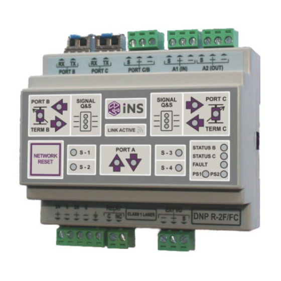
Locations of Interface ports, LEDs and DIP-switches LED Indicators Colour Status Description Q &S LED C1/ Q &S LED B1 Q &S LED C2/ LEDs are used to indicate the Router Mode State Q &S LED B2 Q &S LED C3/ Q &S LED B3 Green A good data packet has been transmitted out of port B... - Page 10 Power supply 1 is HEALTHY Power supply 1 Green CPLD has failed [OR] if Fault LED is Flashing PSU1 has failed FLASH CPLD Heartbeat Power supply 2 Green Power supply is HEALTHY Table 9 Figure 3: Node Display SFP signing All of the supplied SFP transceivers are signed to mark calibration with the DNP R-2F/FC product and any non-signed transceivers must NOT be used with the DNP R-2F/FC.
-
Page 11: Dip Switch Settings
DIP-switch settings Before accessing the internal DIP-switch and jumper settings: Prevent damage to internal electronics from electrostatic discharges (ESD) by discharging your body to a grounding point (e.g. use of a wrist strap). For internal DIP SWITCH setting information, refer to the DNP R-2F/FC Advanced User Manual. The configuration setting for use with Kentec fire alarm panels has been simplified so that you only need to set Rotary switch (Rot SW 1) for the DNP R-2F/FC, (refer to Figure 4) which is externally accessible. - Page 12 Switch settings for DNP R-2F/FC operation Rotary selector switch settings for communication configuration The rotary selector switch, located on the DNP R-2F/FC as shown in Figure 5, has the setting associations shown in Table 10. Rotary selector switch Figure 5: Rotary selector Rot Switch Setting Position Function...
- Page 13 Not Used Not Used Not Used Not Used Not Used Not Used Not Used Not Used Not Used Not Used Table 10 Man-1572 DNP-R-2F/FC-K...
-
Page 14: Configuration And Installation
Unit specific description Signal propagation delay and jitter Many CIE (e.g. Fire panel) only offer tight timing requirements for supporting a class A redundant ring application. With the introduction of third-party equipment into an OEM redundant transmission path, additional signal delays and jitter are often introduced with the original CIEs no longer able to function as required. -
Page 15: Field Applications
Field applications BiDi SFP Transceivers (Bi-directional transceivers) The DNP R-2F/FC can also be used to convert a dual fibre radial link to a redundant dual path as per Figure 13 by using the BiDi SFP transceivers. The BiDi transceivers use two frequencies for Tx and Rx on each fibre to carry the Tx and Rx signals on a single fibre. - Page 16 RS-485 cable screen connection with the DNP R-2F/FC used in hybrid medium mode When the DNP R-2F/FC is used in hybrid medium mode, the screen on the metallic conductor (cable) needs to be earthed on one of the two sides to provide a path to ground any coupled signal interference.
- Page 17 Mixed Optic Fibre cable types (e.g. Single Mode and Multi-mode) The DNP R-2F/FC supports a network that has mixed cable types by selecting the correct SFP transceiver for the cable to which it is connected. Transceiver types supported: Multi-mode (MM) Single Mode (SM) Bi-directional (BiDi) Figure 8: Connections of Mixed Optic Fibre Types...
- Page 18 Redundant Power Supply The DNP R-2F/FC module supports dual power supplies with automated switchover. A The typical configuration for connecting and auxiliary and backup battery power supplies is illustrated in Figure 9. Figure 9: Example of a configuration for redundant power supply Man-1572 DNP-R-2F/FC-K...
-
Page 19: Referring Documents
About the interfaces Power terminal The power terminal has two independent inputs, +Voltage A and +Voltage B. These have been included to support redundancy should either of the two fail. RS-485 interface Two connectors with three-position detachable screw terminals support the connections for the 4 port 2 wire RS-485 system. -
Page 20: Wiring Connections
Wiring connections Figure 10a and 10b illustrates the wiring connections for the DNP R-2F/FC modules. Note: The port connections must have Port B connected to Port C as presented in the diagram. Figure 10a: Passive Mode Settings and Dual Port CIE Connections Man-1572 DNP-R-2F/FC-K... - Page 21 Figure 10b: Passive Mode Settings and Dual Port CIE with Hybrid Connections Man-1572 DNP-R-2F/FC-K...
- Page 22 Figure 10c: Passive mode settings and single port CIE Connections for a radial link Man-1572 DNP-R-2F/FC-K...
-
Page 23: Sfp Transceivers
SFP Transceivers The SFP transceivers used with the DNX R-2F/FC product are presented in Figure 11. Figure 11a: INS010 – Multimode transceiver Figure 11b: INS011 – Single mode transceiver Figure 11c: INS012 – Single mode Bi-directional transceiver (To pair with the INS013) Figure 11d: INS013 –... - Page 24 Figure 12: INS LED Indication Man-1572 DNP-R-2F/FC-K...
Need help?
Do you have a question about the DNP-R-2F-K and is the answer not in the manual?
Questions and answers