Table of Contents
Advertisement
Quick Links
Operations and Maintenance Manual
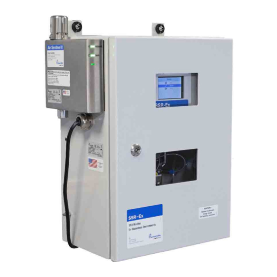
Total Residual Oxidant Monitor for
Use in Hazardous Environments
Model SSR-Ex 28037
IOM-HF-SSR-Ex 28037 Rev 5
WARNING
!
Read this Manual BEFORE using this equipment.
Failure to read and follow all safety and use information can
result in death, serious personal injury, property damage, or
damage to the equipment.
Keep this Manual for future reference.
IOM-HF-SSR-Ex 28037
Advertisement
Table of Contents

Subscribe to Our Youtube Channel
Related Manuals for Watts HF scientific SSR-Ex 28037


Summary of Contents for Watts HF scientific SSR-Ex 28037
- Page 1 IOM-HF-SSR-Ex 28037 Operations and Maintenance Manual Total Residual Oxidant Monitor for Use in Hazardous Environments Model SSR-Ex 28037 WARNING Read this Manual BEFORE using this equipment. Failure to read and follow all safety and use information can result in death, serious personal injury, property damage, or damage to the equipment.
-
Page 2: Table Of Contents
Table of Contents 1.0 Safety ................... 3 6.0 Maintenance ................15 1.1 Understanding Safety Information ........... 3 6.1 Calibration ................15 2.0 Overview ..................3 6.2 Cuvette Replacement ............16 2.1 Specifications ................. 4 6.3 T-Strainer Cleaning ............... 16 2.2 Unpacking and Inspection of the Instrument and Accessories ..5 6.4 Adjusting the Pressure Regulator .......... -
Page 3: Safety
1.0 Safety 2.0 Overview 1.1 Understanding Safety Information This instrument has been specifically designed for TRO measurement and to operate in hazardous atmospheres meeting the IECEx and ATEX This manual contains safety and use instructions that must be ratings as stated in the specifications. The instrument uses an IECEx followed during the installation, commissioning, operation, care and approved purge/ pressurization controller called the Air Sentinel II. -
Page 4: Specifications
2.1 Specifications Measurement Range 0.00 – 15.00 mg/l (PPM) Accuracy ±10% of reading or ±0.03 mg/l (PPM) whichever is greater for range of 0 - 15.0 mg/l (PPM) Resolution 0.01 mg/l (PPM) Cycle Time Adjustable; 45 seconds to 10 minutes (600 seconds) Display 3.5"... -
Page 5: Unpacking And Inspection Of The Instrument And Accessories
3.0 Components Listing 2.2 Unpacking and Inspection of the Instrument and Accessories 3.1 Electronics Compartment The table below indicates the items included in the shipment. ELECTRONICS COMPARTMENT Item Quantity (AIR PURGED WHEN SCREWED CLOSED) SSR-Ex Monitor Includes - Factory installed Air Sentinel II SHOWN OPEN TO ALLOW CONNECTIONS AIR SENTINEL II Owner’s Manual... -
Page 6: Wet Section Of Enclosure Fittings And Items Listing
4.0 Installation 3.4 Wet Section of Enclosure Fittings and Items Listing 4.1 Mounting and Site Selection The instrument is designed for wall mounting. Choose a location that is easily accessible for operation and service. It is recommended that the display window is about eye level. Consideration must be made for the plumbing, air, and electrical conduit connections. -
Page 7: Plumbing And Air Connections
4.2 Plumbing and Air Connections EMERGENCY DRAIN (NO CONNECTION NEEDED) SAMPLE WATER (6mm connection) To avoid injury, death, fire, explosion, leak, or property damage: MAIN DRAIN (12 mm connection) PURGE AIR (AIR ONLY 6mm • The fluid waste from the drain connection MUST NEVER connection) BE reintroduced into the incoming water stream. -
Page 8: Low Voltage Connections
4.3.1.3 Modbus The RS-485 half-duplex (2-wire) digital interface operates with All low voltage connections should be completed before the differential levels that are not susceptible to electrical interferences. main power is connected to system. Therefore, cable lengths up to 3000 ft can be implemented. The last device on every bus may require a 120-ohm termination resistor to All electrical connections must pass through a compression eliminate the possibilities of signal reflection on the line. -
Page 9: Modbus Control
4.5 Modbus Control 4.5.2.2 Format 16-bit word format In addition to the above mentioned Remote Standby Connections, control can also be achieved using Modbus control. Two special Modbus addresses are provided. The reading cycle is initiated using the Coil Address 00005 with the default at False (0). Setting this Bit 15 Bit 14 Bit 13 Bit 12 Bit 11 Bit 10 Bit 9 Bit 8 Bit 7 Bit 6 Bit 5 Bit 4 Bit 3 Bit 2 Bit 1 Bit 0 Address to True (1) initiates the reading cycle. -
Page 10: Securing The Electrical Enclosure
4.5.4.4 Definitions Address Type Register Min Default Max Function 40010 RS-485 baud 0 – 1,200 Address Type Register Function 1 – 2,400 30001, Float Sensor read- The meter reading 2 – 4,800 30002 3 – 9,600 4 – 19,200 30003, Float ABS The absorbance 30004... -
Page 11: Configuration - General Process
5.0 Configuration - General Service Menu Options Process Title Function/Description PRIME Prime DPD and Buffer Reagents. 5.1 Instrument Commissioning and CALIBRATE Initiate Calibration Procedure. Follow Start-up prompts to complete. WATER PRIME Actuate the sample pump to flush the After all water, air, and electrical connections have been made, the water lines. -
Page 12: Menu Selection Options
5.2.1 Menu Selection Options 5.2.1.1 Main Menu 5.2.1.2 Config Menu HOME No Change ANALOG OUTPUT (see 4.2.1.3) MODBUS (see 4.2.1.4) ALARMS (see 4.2.1.5) PRIME UNITS (see 4.2.1.6) AVERAGE (see 4.2.1.7) PRESS SELECT TO SERVICE CALIBRATE ACCESS BACKLIGHT (see 4.2.1.8) CONFIG CYCLE TIME (see 4.2.1.9) WATER PRIME... -
Page 13: Analog Output Menu
5.2.1.3 Analog Output Menu 5.2.1.5 Alarms Menu ERROR LEVEL ALARM 1 TYPE 4 mA ALARM 1 SETPOINT ANALOG OUTPUT 20 mA ALARMS ALARM 2 TYPE 4 mA CALIBRATE ALARM 2 SETPOINT 20 mA CALIBRATE (Select using UP & DOWN buttons) SSR-Ex allows the alarms to be configured to be either HI, LO, OFF or Select using UP &... -
Page 14: Cycle Time Menu
5.2.1.9 Cycle Time Menu 5.2.1.13 Restore Factory Cal Menu RESTORE FACTORY CAL RESTORE FACTORY CAL? CYCLE TIME 45 - 600 This option will restore the factory default calibration. Screen displays (Select using UP & DOWN buttons) Values are in seconds. “RESTORE FACTORY CAL?”... -
Page 15: System Start-Up
5.3 System Start-up maintenance, while the SSR-Ex instrument is powered, air supplied, and while the main enclosure door is open. Under normal operating conditions, Once the SSR-Ex is powered on, air has been purged, and all it is recommended that the main enclosure door is closed. In cases where configurations have been completed, it is ready for use. -
Page 16: Cuvette Replacement
6.2 Cuvette Replacement 6.6 Replacing the Peristaltic Sample Pump Head HF scientific recommends that the cuvette be replaced annually or if it appears badly soiled or discolored at any time. It is suggested to place The pump head assembly can be replaced. Recommended replacement a covering over a floor grate if the instrument is installed over a grate. -
Page 17: Diagnostic/Troubleshooting Chart
8.0 Error/Alarm Messages and Pressure Regulator (Inlet Description - Includes Qty. of 1, As needed Suggested Actions Water) - 24320S Watts Pressure Regulator ® ERROR DISPLAYED Definition Suggested Action To order any accessory or replacement part, please contact the HF scientific Customer Service Department. - Page 18 Notes _ _ _ _ _ _ _ _ _ _ _ _ _ _ _ _ _ _ _ _ _ _ _ _ _ _ _ _ _ _ _ _ _ _ _ _ _ _ _ _ _ _ _ _ _ _ _ _ _ _ _ _ _ _ _ _ _ _ _ _ _ _ _ _ _ _ _ _ _ _ _ _ _ _ _ _ _ _ _ _ _ _ _ _ _ _ _ _ _ _ _ _ _ _ _ _ _ _ _ _ _ _ _ _ _ _ _ _ _ _ _ _ _ _ _ _ _ _ _ _ _ _ _ _ _ _ _ _ _ _ _ _ _ _ _ _ _ _ _ _ _ _ _ _ _ _ _ _ _ _ _ _ _ _ _ _ _ _ _ _ _ _ _ _ _ _ _ _ _ _ _ _ _ _ _ _ _ _ _ _ _ _ _ _ _ _ _ _ _ _ _ _ _ _ _ _ _ _ _ _ _ _ _ _ _ _ _ _ _ _ _ _ _ _ _ _ _ _ _ _ _ _ _ _ _ _ _ _ _ _ _ _ _ _ _ _ _ _ _ _ _ _ _ _ _ _ _ _ _ _ _ _ _ _ _ _ _ _ _ _ _ _ _ _ _ _ _ _ _ _ _ _ _ _ _ _ _ _ _ _ _ _ _ _ _ _ _ _ _ _ _ _ _ _ _ _ _ _ _ _ _ _ _ _ _ _ _ _ _ _ _ _ _ _ _ _ _ _ _ _ _ _ _ _ _ _ _ _ _ _ _ _ _ _ _ _ _ _ _ _ _ _ _ _ _ _ _ _ _ _ _ _ _ _ _ _ _ _ _ _ _ _ _ _ _ _ _ _ _ _ _ _ _ _ _ _ _ _ _ _ _ _ _ _ _ _ _ _ _ _ _ _ _ _ _ _ _ _ _ _ _ _ _ _ _ _ _ _ _ _ _ _ _ _ _ _ _ _ _ _ _ _ _ _ _ _ _ _ _ _ _ _ _ _ _ _ _ _ _ _ _ _ _ _ _ _ _ _ _ _ _ _ _ _ _ _ _ _ _ _ _ _ _ _ _ _ _ _ _ _ _ _ _ _ _ _ _ _ _ _ _ _ _ _ _ _ _ _ _ _ _ _ _ _ _ _ _ _ _ _ _ _ _ _ _ _ _ _ _ _ _ _ _ _ _ _ _ _ _ _ _ _ _ _ _ _ _ _ _ _ _ _ _ _ _ _ _ _ _ _ _ _ _ _ _ _ _ _ _ _ _ _ _ _ _ _ _ _ _ _ _ _ _ _ _ _ _ _ _ _ _ _ _ _ _ _ _ _ _ _ _ _ _ _ _ _ _ _ _ _ _ _ _ _ _ _ _ _ _ _ _ _ _ _ _ _ _ _ _ _ _ _ _ _ _ _ _ _ _ _ _ _ _ _ _ _ _ _ _ _ _ _ _ _ _ _ _ _ _ _ _ _ _ _ _ _ _ _ _ _ _ _ _ _ _ _ _ _ _ _ _ _ _ _ _ _ _ _ _ _ _ _ _ _ _ _ _ _ _ _ _ _ _ _ _ _ _ _ _ _ _ _ _ _ _ _ _ _ _ _ _ _ _ _ _ _ _ _ _ _ _ _ _ _ _ _ _ _ _ _ _ _ _ _ _ _ _ _ _ _ _ _ _ _ _ _ _ _ _ _ _ _ _ _ _ _ _ _ _ _ _ _ _ _ _ _ _ _ _ _ _ _ _ _ _ _ _ _ _ _ _ _ _ _ _ _ _ _ _ _ _ _ _ _ _ _ _ _ _ _ _ _ _ _ _ _ _ _ _ _ _ _ _ _ _ _ _ _ _ _ _ _ _ _ _ _ _ _ _ _ _ _ _ _...
- Page 19 Notes _ _ _ _ _ _ _ _ _ _ _ _ _ _ _ _ _ _ _ _ _ _ _ _ _ _ _ _ _ _ _ _ _ _ _ _ _ _ _ _ _ _ _ _ _ _ _ _ _ _ _ _ _ _ _ _ _ _ _ _ _ _ _ _ _ _ _ _ _ _ _ _ _ _ _ _ _ _ _ _ _ _ _ _ _ _ _ _ _ _ _ _ _ _ _ _ _ _ _ _ _ _ _ _ _ _ _ _ _ _ _ _ _ _ _ _ _ _ _ _ _ _ _ _ _ _ _ _ _ _ _ _ _ _ _ _ _ _ _ _ _ _ _ _ _ _ _ _ _ _ _ _ _ _ _ _ _ _ _ _ _ _ _ _ _ _ _ _ _ _ _ _ _ _ _ _ _ _ _ _ _ _ _ _ _ _ _ _ _ _ _ _ _ _ _ _ _ _ _ _ _ _ _ _ _ _ _ _ _ _ _ _ _ _ _ _ _ _ _ _ _ _ _ _ _ _ _ _ _ _ _ _ _ _ _ _ _ _ _ _ _ _ _ _ _ _ _ _ _ _ _ _ _ _ _ _ _ _ _ _ _ _ _ _ _ _ _ _ _ _ _ _ _ _ _ _ _ _ _ _ _ _ _ _ _ _ _ _ _ _ _ _ _ _ _ _ _ _ _ _ _ _ _ _ _ _ _ _ _ _ _ _ _ _ _ _ _ _ _ _ _ _ _ _ _ _ _ _ _ _ _ _ _ _ _ _ _ _ _ _ _ _ _ _ _ _ _ _ _ _ _ _ _ _ _ _ _ _ _ _ _ _ _ _ _ _ _ _ _ _ _ _ _ _ _ _ _ _ _ _ _ _ _ _ _ _ _ _ _ _ _ _ _ _ _ _ _ _ _ _ _ _ _ _ _ _ _ _ _ _ _ _ _ _ _ _ _ _ _ _ _ _ _ _ _ _ _ _ _ _ _ _ _ _ _ _ _ _ _ _ _ _ _ _ _ _ _ _ _ _ _ _ _ _ _ _ _ _ _ _ _ _ _ _ _ _ _ _ _ _ _ _ _ _ _ _ _ _ _ _ _ _ _ _ _ _ _ _ _ _ _ _ _ _ _ _ _ _ _ _ _ _ _ _ _ _ _ _ _ _ _ _ _ _ _ _ _ _ _ _ _ _ _ _ _ _ _ _ _ _ _ _ _ _ _ _ _ _ _ _ _ _ _ _ _ _ _ _ _ _ _ _ _ _ _ _ _ _ _ _ _ _ _ _ _ _ _ _ _ _ _ _ _ _ _ _ _ _ _ _ _ _ _ _ _ _ _ _ _ _ _ _ _ _ _ _ _ _ _ _ _ _ _ _ _ _ _ _ _ _ _ _ _ _ _ _ _ _ _ _ _ _ _ _ _ _ _ _ _ _ _ _ _ _ _ _ _ _ _ _ _ _ _ _ _ _ _ _ _ _ _ _ _ _ _ _ _ _ _ _ _ _ _ _ _ _ _ _ _ _ _ _ _ _ _ _ _ _ _ _ _ _ _ _ _ _ _ _ _ _ _ _ _ _ _ _ _ _ _ _ _ _ _ _ _ _ _ _ _ _ _ _ _ _ _ _ _ _ _ _ _ _ _ _ _ _ _ _ _ _ _ _ _ _ _ _ _ _ _ _ _ _ _ _ _ _ _ _ _ _ _ _ _ _ _ _ _ _ _ _ _ _ _ _ _ _ _ _ _ _ _ _ _ _ _ _ _ _ _ _ _ _ _ _ _ _ _ _ _ _ _ _ _ _ _ _ _ _ _ _ _ _ _ _ _ _ _ _ _ _ _ _ _ _ _ _ _ _ _ _ _ _ _ _...
-
Page 20: Limited Warranty
11.0 Limited Warranty Watts Regulator Co. (the “Company”) warrants each ballast water market instrument product to be free from defects in material and workmanship under normal usage for a period of two (2) years from first use or three (3) years from date of the Company’s invoice from the original sale of the product, whichever occurs first.
Need help?
Do you have a question about the HF scientific SSR-Ex 28037 and is the answer not in the manual?
Questions and answers