Table of Contents
Advertisement
Quick Links
Advertisement
Table of Contents

Summary of Contents for SAFE TRON CU2
- Page 1 20211129 Instruction manual CONTROL UNIT CU2...
-
Page 2: Table Of Contents
CONTENTS Important notice Specifications Recommendations Cable dimensions SSF 3522 Terminal layout CU2 Connecting one motor lock Installing older 6000-series motor locks Connecting two motor lock Terminal description Replacing units Activating re-entry mode Menu items 10-12 Error log Warnings log Accessories... -
Page 3: Important Notice
IMPORTANT NOTICE SAFETRON motor lock and strike plates is intended for use by the general public where there is more incentive to be careful and where there is a high risk of abuse, such as doors in public buildings. Intended for doors up to 200 kg door mass, 15 N maxi- mum closing force. -
Page 4: Specifications
SPECIFICATIONS Safetron motorlock serie 6000 is tested and certified according to SS-EN 14846:2008, SS-EN 179:2008 and SSF 3522 class 2B, 3, 4, 5 Safetron slutbleck i 6000 serien är testade och certifierade enligt EN 12209 samt SSF 3522, klass 5. Motorlock 6100, 6300 and 6500 meets following requirement according to SS-EN 14846:2008 Category of Durability... -
Page 5: Recommendations
RECOMMENDATIONS UPON INSTALLATION • Read and follow the installationmanual. • Motor lock should be used primarily electronically for best function. • Service like tex. adjustment and lubricate shall be made by an certificated installer. CALCULATION OF CABLE DIMENSIONS Avoid the use of data/tele/signal cables (singel conductor) with cablearea between 0,1 - 0,2 as an powersupply for the motorlock. -
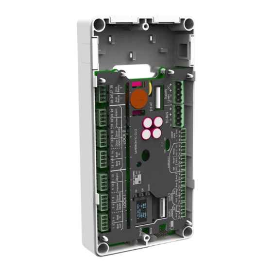
Page 6: Terminal Layout Cu2
TERMINAL LAYOUT... -
Page 7: Connecting One Motor Lock
NC: move the short circuit jumper to the two most right pins INSTALLATION OF OLDER 6000 (MFD BEFORE 2020-09) In order to use control unit TC CU2 with older motor locks in the 6000-series the communication settings have to be altered. This is done through the motor locks display. -
Page 8: Connecting Two Motor Lock
CONNECTING TWO MOTOR LOCKS CONNECTING LOCK CASE Connect the lock case to the control unit via the terminal block on the back of the lock case. The cable is then connected to terminal block LOCK COM on the control unit where power supply +/- and communication A and B are found. -
Page 9: Terminal Description
TERMINAL DESCRIPTION Terminal Name Description Bolt out Activated when the bolt is out in the locked position Bolt in Activated when the bolt is in in the unlocked position Door open Controlled through the built-in magnetic door sensor Door closed Controlled through the built-in magnetic door sensor 9-10 Impuls... -
Page 10: Menu Items
MENU ITEMS CONTROL UNIT DISPLAY Our control units are equipped with a display that can be navigated to ease with configuration and status output. Status 0 Door1: Closed Toggle the menu with the buttons marked ’UP’ and ’DOWN’. Lock1: Locked The button ’OK’... - Page 11 MENU ITEMS CONTROL UNIT Bold text indicates factory settings. NO MENU VARIABLES DESCRIPTION Aux1 : AUX inputs for lock 1. Adjustable NO / NC Aux1 : Choose function for lock 1: • Dayblock : Upon closed circuit the lock is held unlocked after the first activation until this circuit has been released Aux1 : NO | NC...
- Page 12 S/N : Serial number on the control unit S/N : F/W : Firmware on the control unit F/W : CU2 info1 H/W : Hardware version on the control unit H/W : M/N : Model number on the control unit M/N :...
-
Page 13: Error Log
ERROR MENU The control unit logs all errors in menu 21 which is found in the display of the control unit. Example 07:43:21 Time of error Error code ERROR LOG (MENU 21) Errors that require immediate attention. Error diod is lit when errors are present in the log ERROR DESCRIPTION PD Disconnected... -
Page 14: Strike Plate Placement
STRIKE PLATE OFFSET PLACEMENT SAFETRON 6100, 6200, 6300 Recommended strike plate placement for motor locks 6100 and 6200 is measured from the under side of the lock face plate and strike plate: 7,00mm +5,5mm -2,5mm Recommended strike plate placement for motor lock 6300 is measured from the under side of the lock face plate and strike plate: 7,00mm +5,5mm -2,5mm 7mm +/- 3mm 6000 Narrow style 12,50 Max... -
Page 15: Installation Of Lock Case (6100/6500)
INSTALLATION OF LOCK CASE SAFETRON 6100 R16,50... -
Page 16: Installation Of Lock Case (6200/6600)
INSTALLATION OF LOCK CASE SAFETRON 6200 R16,50 8. RUBRIK... -
Page 17: Installation Of Lock Case (6300)
INSTALLATION OF LOCK CASE SAFETRON 6300 8. RUBRIK... -
Page 18: Cut Out Drawings
CUT OUT DRAWINGS SAFETRON 6100 & 6200 Lock case depth 75 mm 8. RUBRIK Required only for locks with latchbolt SAFETRON 6300 R12,50 Cylinder Cable in and output Lock case depth 53... -
Page 19: Maintenance Of Motor Locks
MAINTENANCE SAFETRON MOTOR LOCK • Maintenance should be performed by a trained professional • Ensure that mounted knobs, handles and cylinders are working satisfactory • Lubricate and make adjustments as necessary • In normal use lubricate the lock housing mechanical parts once a year. - Page 20 SAFETRON AB Tel: +46 54 19 02 45 Säterivägen 18 info@safetron.com P.O. Box 2096 www.safetron.com 65002 Karlstad Sweden...
Need help?
Do you have a question about the CU2 and is the answer not in the manual?
Questions and answers