
Subscribe to Our Youtube Channel
Summary of Contents for TCP WPC-832-Modbus
- Page 1 2-Port Modbus RTU/ASCII To Modbus TCP Gateway WPC-832-Modbus User Manual v.201808b http://www.tcpipweb.com *** this user manual is subject to change without prior notice.
-
Page 2: Table Of Contents
Web Browser Configuration --------------------------------------------------------------------------------------------------------- 14 System Setup ------------------------------------------------------------------------------------------------------------------ 14 Network setup ---------------------------------------------------------------------------------------------------------------- 16 Serial Port page --------------------------------------------------------------------------------------------------------------- 20 Gateway page (Serial port over TCP/IP) -------------------------------------------------------------------------------- 21 Testing Verification ----------------------------------------------------------------------------------------------------------------------- 23 Hyper Terminal for TCP/IP ----------------------------------------------------------------------------------------------------------- 23 Hyper Terminal for COM Port ------------------------------------------------------------------------------------------------------- 26... -
Page 3: Introduction
Introduction WPC-832-Modbus RTU/ASCII to TCP Gateway provides the easy way of connecting Modbus Serial devices to Wireless and Ethernet LAN in Modbus TCP and RTU/ASCII networks at the same time. The wireless supports 802.11 b/g/n in AP/Station mode with WEP/WPA/WPA2 encryption for data transmission security. -
Page 4: Overview
WPC-832-Modbus providing TCP Server Mode, TCP Client Mode, and UDP Mode for selection. It supports manual configuration via web browser and support various protocols including TCP, IP, UDP, HTTP, DHCP, ICMP, and ARP. These are the best solution to coordinate your Serial interface devices. -
Page 5: Package Check List
Package Check List WPC-832-Modbus 2-Port Modbus RTU/ASCII To Modbus TCP Gateway product attached with the following items: 1 unit of Serial to WPC-832-Modbus Gateway 1 unit of Power Adaptor (12V DC, 1A) is an option 1 unit of dipole antenna(2.0dBi) Documentation &... -
Page 6: Product Specifications
Port Type : RJ-45 Connector Speed : 10 /100 M bps ( Auto Detecting ) Protocol : ARP , IP , ICMP , UDP , TCP , HTTP , DHCP Protocol:NTP, FTP Mode : TCP Server / TCP Client / UDP ... - Page 7 Led Lamp : SYS, PWR, PoE(option), WiFi, RX, TX, LAN RTC : Real Time Clock Watch Dog Function Software : TCP TO RTU Slave, RTU Master TO TCP Slave , TCP TO ASCII Slave, ASCII Master TO TCP Slave Warranty ...
-
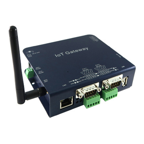
Page 8: Product Panel Views
Product Panel Views Antenna USB host for OpenWrt only RS-232/422/485 Ethernet RJ45 Antenna Connector The connector for antenna is a standard reverse SMA jack. Simply connect it to a 2.0dBi dipole antenna (Standard Rubber Duck) and it is 50 Ohms impedance and can support 2.4GHz frequency Ethernet Port The connector for network is the usual RJ45. - Page 9 DC-IN Power Outlet The Serial to Ethernet+WiFi Converter is powered by a single 12V DC (Inner positive, outer negative) power supply and 1A Current. Connect the power adaptor to the AC power socket and put the DC Jack plug into the outlet of device. The “SYS” green color LED will be ON when power is properly supplied.
-
Page 10: Wiring Architecture
DC-IN Power Outlet The Device is powered by a 12V DC (Inner positive, outer negative) , 1.0A power supply. Plugging the power adaptor to the AC power socket and put the DC Jack plug into the outlet of the Device. The “SYS”... -
Page 11: Configuration
Configuration When setting up your Gateway for the first time, the first thing you should do is to configure the IP address. The following topics are covered in this chapter: IP Search Utility Setup Web Browser Configuration... -
Page 12: Ip Search Utility Setup
IP Search Utility Setup Copy “CvIotFinder Setup.exe” from CD ROM to your host computer. “CvIotFinder” is a self-extract-install program. Double click it to install this Wi-Fi IP Searching tool into host computer. Upon running IP search tool (CvIotFinder), if a firewall warning pop up, please click to accept the program pass through firewall. - Page 13 Click “Setup” button will pop up a window. You may change Name, Description, IP, Netmask of device. Click “Setup” to save setup. The device’s IP must be same subnet with host PC/NB enable to use web browser open configuration page. Click “Goto”...
-
Page 14: Web Browser Configuration
Web Browser Configuration There are 4 setup pages as “System”, “Network”, “Serial” and “Over TCP/IP”. System Setup 1.1 System: where you can change Password, set up Auto Reset time and modify Device Name, Description of device. 1.2 Appearance of Wireless ad Ethernet setup. - Page 15 1.3 NTP: Enable / Disable NTP function; Set up NTP server and Time Zone. 1.4 Firmware update: If necessary, click “Browse” to open file manager. Then, select the file with specified version and click “open” button. When the selected file name appears on the input column, click “Update” button. 1.5 Up to now, Setup is successfully configured.
-
Page 16: Network Setup
Network setup 2.1 Wireless section: 2.1.1 Type: Click to select “Access Point” or “Infrastructure”. “Infrastructure” is for connecting to a local Router. 2.1.2 If select “ACCESS POINT”, input password for the AP and assign IP address with “DHCP” or “STATIC”. - Page 17 2.1.3 When selected “ACCESS POINT”, this Device acts as an Access Point which is allowed to be connected by PC /NB /Smart Phone/ PAD. It supports DHCP server function. Soft AP broadcasts its SSID “CVIoT_XX_XX_XX_XX_XX_XX”. PC /NB /Smart Phone/PAD should connect to this SSID and then able to open web browser with default IP of this Device.
- Page 18 2.1.7 If The Type selected with “Infrastructure”, set SSID of Router and the other inputs. 2.1.8 Go to item SSID, click “Scan” will get list of available SSID of Access Points, select the one in your network to link. For example: 2.1.9 On the NB/PC, choose same SSID to link.
- Page 19 2.2 Ethernet section: select “STATIC” or “DHCP” to assign IP address. 2.3 Gateway and DNS section: check with MIS for right IP address. The Gateway must be set with correct IP enable to connect with Internet. 2.4 Up to now, Setup is successfully configured. Please click “Save” for this page temporarily and go to other pages for configuration or click “Save and Restart”...
-
Page 20: Serial Port Page
Serial Port page Please clearly set each parameters from Serial 1 to Serial 2 (default 9600,n,8,1). 3.1 Baud Rate: 300 bps to 921.6K bps 3.2 Parity: None, Even, Odd 3.3 Data Bits: 5, 6, 7, 8 3.4 Stop Bits: 1, 2 3.5 Flow Control: None, XON/XOFF 3.6 RxDelay(ms) 3.7 TxDelay(ms) -
Page 21: Gateway Page (Serial Port Over Tcp/Ip)
4.1 There are “Modbus Gateway” #1 and #2 port. 4.2 Gateway Type: 4 types for selection or to disable. 4.3 For RTU To TCP Slave can set up to 8 slaves. 4.2 Up to now, Setup is successfully configured. Please click “Save” and go to other pages for... - Page 22 4.3 After configued all parameters, click “Save and Restart” to reboot system.
-
Page 23: Testing Verification
The operating system can be Window 7/8/10. The “Hyper Terminal” utility should be installed on host PC/NB. The following topics are covered in this chapter: □ Hyper Terminal for TCP/IP □ Hyper Terminal for COM Port □ Data Transmission 5.1 Hyper Terminal for TCP/IP... - Page 24 5.1.2 Key in a file name of connection (eg. test) and then click “OK”. 5.1.3 Choose TCP/IP, then click “OK”.
- Page 25 5.1.4 Key in the Converter’s IP address and Socket port then click “OK”. *for testing RS-232: default Port Number is 100 *for testing RS-422/485: default Port number is 101 5.1.5 A HyperTerminal window will show up. The time counter start at the down left corner if connect is correct.
-
Page 26: Hyper Terminal For Com Port
5.1.7 If not able to type or not seen any character present in the window, please check every step from beginning of this procedure. 5.2 Hyper Terminal for COM Port 5.2.1 For RS-485 testing: It needs two devices to connect the Terminal Block D+ to D+ and D- to D-. In RS-422/485 setup page: choose RS485. -
Page 27: Reset (If Needed)
6. Reset (if needed) Ensure power is on, press “WiFi Reset” button for over 25 seconds then release. WPC-832 will set configuration back to default. -
Page 28: Pin Assignment
Pin Assignment DC Power outlet RS-232 Pin Assignment The pin assignment scheme for a 9-pin male connector on a DTE is given below. PIN 1 : DCD PIN 2 : RXD PIN 3 : TXD PIN 4 : DTR PIN 5 : GND PIN 6 : DSR PIN 7 : RTS...
Need help?
Do you have a question about the WPC-832-Modbus and is the answer not in the manual?
Questions and answers