
Summary of Contents for Stealth Designer+ SC-09FM-HP230
- Page 1 UNIVERSAL FLOOR/CEILING INSTALLATION MANUAL Models: SC-09FM-HP230 SC-12FM-HP230 SC-18FM-HP230 SC-24FM-HP230...
-
Page 2: Table Of Contents
Thank you for choosing a Stealth Universal Floor/Ceiling Ductless Heat Pump System Please read this installation manual carefully before installing and starting up the Floor/Ceiling Ductless System. Take a moment to fill out the product and installation form on the back cover. Retain both the manual and installation record for future reference. -
Page 3: Safety Precautions
SAFETY PRECAUTIONS Please read the following before installation. This is the safety alert symbol. It is used to alert you to potential personal injury hazards. Obey all safety messages that follow this symbol to avoid possible injury or death. This mark indicates procedures which, if improperly performed, W RNING might lead to the death or serious injury of the user. -
Page 4: System Requirements
SYSTEM REQUIREMENTS PIPE SIZE in (mm) Unit Size (BtuH) Net/Gross Weight Liquid Line Suction/Gas Line 9,000 1/4 (6) 3/8 (9.5) 88/110 lbs. 12,000 1/4 (6) 3/8 (9.5) 88/110 lbs. 18,000 1/4 (6) 1/2 (12) 88/110 lbs. 24,000 3/8 (9.5) 5/8 (16) 100/120 lbs. -
Page 5: Suggested Tools
SUGGESTED TOOLS • Standard Wrench • Adjustable/Crescent Wrench • Torque Wrench • Hex Keys or Allen Wrenches • Drill & Drill Bits • Hole Saw • Pipe Cutter • Screw drivers (Phillips & Flat blade) • Manifold and Gauges • Level •... -
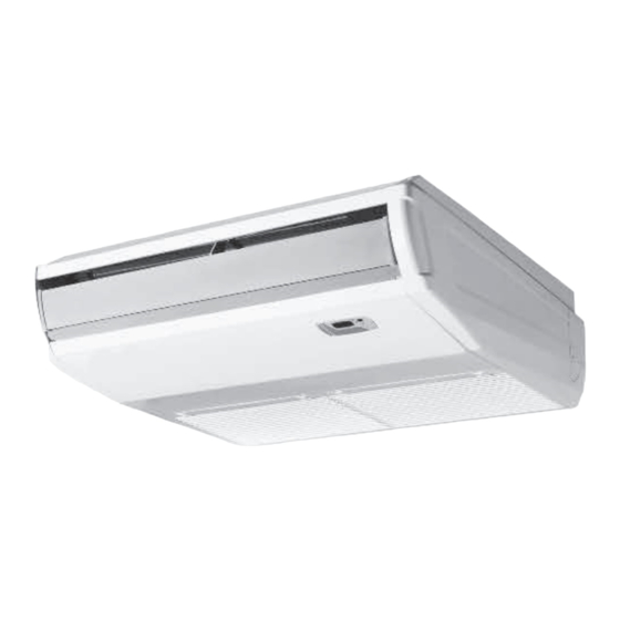
Page 6: System Parts
SYSTEM PARTS Air Outlet Indoor Unit Air inlet Power Supply Part Name 1. Front Cabinet 2. Air Inlet 3. Wired Controller (Optional) 4. Remote Controller 5. Drain Pipe 6. Gas Pipe 7. Liquid Pipe 8. Service Cover 9. Front Panel Air inlet Outdoor Unit Air outlet... -
Page 7: Installation Site Instructions
INSTALLATION SITE INSTRUCTIONS Indoor Unit W RNING The unit must be installed in a location which can withstand four times the weight of the unit. Inadequate support may result in serious property damage and injuries. Select a site that allows for the following: Ensure the installation complies with the installation minimum dimensions and meets the •... -
Page 8: Indoor Unit Installation
INDOOR UNIT INSTALLATION Indoor Unit Dimensions INDOOR UNIT DIMENSIONS Inches (mm) Model SC-09FM-HP230 48/1220 8.9/225 45.6/1158 11/280 27.6/700 SC-12FM-HP230 48/1220 8.9/225 45.6/1158 11/280 27.6/700 SC-18FM-HP230 48/1220 8.9/225 45.6/1158 11/280 27.6/700 SC-24FM-HP230 48/1220 8.9/225 45.6/1158 11/280 27.6/700 Preparing Indoor Unit for Installation Begin the indoor unit installation by removing the air inlet grille and both side panels from unit as follows: 1. - Page 9 INDOOR UNIT INSTALLATION Laying Out Indoor Location The Universal Floor/Ceiling units allow for wall or ceiling mounting. Follow the instructions for the desire type of installation. Wall Mounting Installation 1. Determine the mounting location on the wall for the indoor unit.
- Page 10 INDOOR UNIT INSTALLATION Ceiling Mounting Installation 1. Determine the mounting location on the ceiling for the indoor unit. Follow the selection criteria in the previous section. 2. Locate the factory supplied installation template included in carton and attach to the ceiling. 3.
-
Page 11: Piping Installation
PIPING INSTALLATION Refrigerant Piping Drill Hole in Wall Indoor Outdoor 1. Locate and mark proper location for the wall hole. Wall Hole Sleeve 2. Cut the wall hole with a 5° to 10° downward Seal Hole slant to the outdoors. See Wall Hole Size table. 3. - Page 12 PIPING INSTALLATION Indoor Unit Pipe Connections 1. Feed refrigerant pipes, drain hose and communication cable assembly through wall hole from outdoor to the Floor/Ceiling indoor unit. 2. Pull the piping assembly to the indoor unit. Carefully bend refrigerant pipes to meet indoor unit connection ports.
- Page 13 PIPING INSTALLATION Outdoor Unit Pipe Connections Indoor Condensate Drain Piping W RNING Observe all local sanitary codes when installing condensate drains. The drain piping should be as short as possible with a constant downward slope. It is recommended to install the condensate drain system with hard polyvinyl chloride (PVC) pipe and matching connectors.
- Page 14 PIPING INSTALLATION Indoor Condensate Drain Piping (con’t) Completing Condensate Drainage Piping • Include the exterior section of condensate hose in the pipe/wire bundle. • Fasten the refrigerant and condensate pipe assembly to the exterior wall for support. • The drain pipe should terminate 6 inches above grade. Test the Condensate Drainage Piping •...
-
Page 15: Power & Wiring
POWER AND WIRING INSTALLATION W RNING 1. Before obtaining access to wire terminals, all electrical supply circuits must be disconnected, locked out and tagged. 2. Always use an independent (dedicated) circuit and provide an independent (dedicated) circuit breaker to supply power to the system. 3. - Page 16 POWER AND WIRING INSTALLATION Electric Wiring Between Indoor Unit and Outdoor Unit Wired Tether Controller XK-19 White Floor/Ceiling Unit Black Cassette Unit Typical Wiring Diagram Green Power: Outdoor Electrical Wiring For Outdoor Unit wire connections, see installation instructions shipped with the outdoor unit. Electrical Connections to Floor Ceiling W RNING Disconnect all electrical power to indoor and outdoor units including disconnects,...
- Page 17 POWER AND WIRING INSTALLATION Indoor Disconnect Switch (Optional) Local codes may require a disconnect switch within sight of the indoor unit. Use a DFS Disconnect Switch Accessory Kit (Part No: DFS-SWITCH-A) to break interconnecting wires going to the N(1), 2, 3, terminals on the indoor unit, as shown in the wiring diagram below: Disconnect Switch Indoor Unit Outdoor Unit...
-
Page 18: Controller Installation And Setup
CONTROLLER INSTALLATION AND SETUP (Optional) The following is a brief overview of the Wired Tether Controller installation. See Tether Controller Owner's Manual for more detailed instructions for setup and operation. Preparation for Installation Select a proper location on the wall for mounting the Tether Controller. -
Page 19: Testing And Inspection
TESTING AND INSPECTION Overview of Display Panel 1. Power Indicator: Power indicator will be on after electrical power is turned on, while it will be off after disconnecting power. 2. COOL Indicator: COOL indicator will be on after COOLmode is activated while it will be off after COOL mode is turned off. -
Page 20: Troubleshooting
TROUBLESHOOTING PROBLEM CAUSE/SOLUTION System does not restart. Cause: The system has a built-in three-minute delay to prevent short and/or rapid cycling of the compressor. Solution: Wait three minutes for the protection delay to expire. Cause: Typically unpleasant odors are the result of mold or mildew forming on the coil surfaces Indoor unit emits unpleasant odor or the air filter. -
Page 21: Diagnostic Codes
DIAGNOSTIC CODES Troubleshooting The unit has onboard diagnostics. The outdoor unit will provide status indicators. The indoor wall unit and remote controller will display error codes. The following is a summary of the codes with explanation: Indoor Unit Outdoor Unit Indicators Malfunction Name Possible Causes &... - Page 22 DIAGNOSTIC CODES Outdoor Unit Indicators Indoor Unit Malfunction Name Possible Causes Display Yellow High Temperature 6 flashes 1) Incorrect refrigerant charge level Resistant Protection and 1 sec Off 2) Refrigerant metering device malfunction 3) Compressor malfunction Cold Air Protection 1) Indoor coil has not reach minimum heating temperature 2) Indoor ambient is abnormally cold 3) Indoor control board malfunction EEPROM Memory Malfunction...
- Page 23 DIAGNOSTIC CODES Outdoor Unit Indicators Indoor Unit Malfunction Name Possible Causes Display Yellow Indoor Coil Freeze Protection - 1) Indoor coil has not reach minimum heating temperature 4 flashes Frequency Decrease/Limit Mode and 1 sec Off 2) Indoor ambient is abnormally cold 3) Indoor control board malfunction Pump Down or Gathering 17 flashes...
- Page 24 DIAGNOSTIC CODES Outdoor Unit Indicators Indoor Unit Malfunction Name Possible Causes Display Yellow Incompatible Indoor and 16 flashes Indoor and outdoor units are not compatible Outdoor Units and 1 sec Off Defrosting Status note 1 16 flashes and 1 sec Off Compressor Phase Current 1) IPM module malfunction Protection...
- Page 25 Phone No. / E-mail STEALTH (1HVAC Energy LLC) warrants this product against failure due to defect in materials or workmanship under normal use and maintenance as follows. All warranty periods begin on the date of original installation. If the date cannot be verified, the warranty period begins one hundred twenty (120) days from date of manufacture.