
Related Manuals for Gantner GT7.2x00


Summary of Contents for Gantner GT7.2x00
- Page 1 GT7.2x00 / GT7.3x00 / GT7.3x01 Multifunctional RFID Terminal Installation & Configuration Document Version 1.2 www.gantner.com HB_GT7-2x00-3x00--EN_12...
- Page 2 GT7 Terminal © Copyright 2021 GANTNER Electronic GmbH Operating instructions, manuals and software are protected by copyright. All rights are reserved. Copying, duplication, translation, installation in any electronic medium or machine-readable form in whole or in part is prohibited. The sole exception is represented by creation of a back-up copy of software for own use as a safeguard, so far as this is technically possible and recommended by us.
- Page 3 - Do not touch the electrical connections while power is being supplied. Format of safety messages that are embedded in text and apply to a specific point: CAUTION! Electrical shock. Never remove safety protection and covers. Do not touch the electrical connections while power is being supplied. www.gantner.com HB_GT7-2x00-3x00--EN_12...
- Page 4 This symbol indicates general information that must be read and followed before proceeding with the accompanying instructions. Mandatory Action: Read Instructions This symbol indicates information referring to an important description in the manual, or other documentation, which must be read and followed. www.gantner.com HB_GT7-2x00-3x00--EN_12...
- Page 5 - Do not attempt to repair a product after a defect, failure, or damage is detected. In addition, do not put the product back into operation. In such cases, it is essential to contact your GANTNER representative or the GANTNER support hotline.
- Page 6 GT7 Terminal The GT7 terminal was developed and fabricated under the quality management standard ISO 9001 and GANTNER Electronic GmbH is also certified according to standard ISO 14001. This product is in conformity with the following EC directives, including all applicable amendments:...
- Page 7 Please send the device article number, serial number, firmware revision, and your contact details (name, address, city, state, and email address) to the following address: Software License Compliance c/o OSS Service Department GANTNER Electronic GmbH Bundesstraße 12 6714 Nüziders Austria This offer is valid to anyone in receipt of this information.
- Page 8 GT7 Terminal www.gantner.com HB_GT7-2x00-3x00--EN_12...
-
Page 9: Table Of Contents
Configuration via G7 Connect (GANTER Cloud) .................. 38 Configuration via Web Interface ......................39 5.6.1 Overview ............................41 5.6.2 Network ............................42 5.6.3 G7 Connect ............................ 44 5.6.4 External Webserver ........................45 5.6.5 Web Proxy ............................. 46 5.6.6 WLAN ............................. 47 www.gantner.com HB_GT7-2x00-3x00--EN_12... - Page 10 Device Maintenance ........................66 5.6.21 Update Firmware ........................... 68 5.6.22 AddonBus (External devices) ......................69 5.6.23 Log Viewer ............................ 70 5.6.24 Device State ..........................71 5.6.25 Legal Information .......................... 72 Integration in Relaxx ..........................73 TECHNICAL DATA ....................... 75 www.gantner.com HB_GT7-2x00-3x00--EN_12...
-
Page 11: Introduction
1 INTRODUCTION About this Manual This manual contains a detailed description of how to install and complete the electrical connections of the GT7.2x00 and GT7.3x00 terminals. The different options for configuring the terminals as well as the technical data are also provided herein. -
Page 12: Formatting
If you have any questions concerning the GT7 terminal, or with any of the other hardware/software products mentioned, please contact your local sales partner or one of the GANTNER branch offices directly. The contact details are available via the following link: www.gantner.com/locations... -
Page 13: General Information
Door contact Network cable (Ethernet) Network and supply (PoE) Network Electronic locker locks (info display of locker no.) To server Sunbed (time control) RFID data carrier Relay box Electronic lock Figure 2.1 – Typical application of the GT7 terminal www.gantner.com HB_GT7-2x00-3x00--EN_12... -
Page 14: Functional Description
Some terms are used frequently in this manual and these are defined below. GT7 Terminal This term refers to all variants of the GT7.2x00, GT7.3x00, and GT73x01 model ranges, regardless of which app is currently active. Since the configuration of the GT7.3x01 (built-in variant) is identical to the GT7.2x00 and GT7.3x00, this manual is also valid in large parts for this variant. -
Page 15: Order Information Guide
The name of the software (app) that is activated on the GT7 terminal to provide the desired functionality. G7 Connect G7 Connect is GANTNER’s Cloud service for the configuration and management of projects that contain multiple GANTNER devices. G7 Connect is accessible via a web browser following registration and login. -
Page 16: Device Features And Dimensions
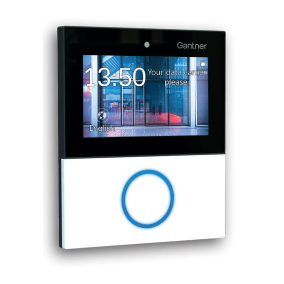
RFID reader with status LED Rear part Front part RFID reader cover Figure 2.2 – GT7 Terminal (example GT7.2x00 and GT7.3x00) Communication Ports The following ports are used for communication with the GT7 terminal. The response ports are chosen randomly. Port Type... -
Page 17: Installation
Installation 3 INSTALLATION The GT7.2x00 and GT7.3x00 terminals are designed for mounting onto a flat, smooth surface. They can be surface mounted or semi-flush mounted in a wall cutout or, alternatively, the terminals can be semi-flush mounted in a desktop. -
Page 18: Installing The Rear Part
► To mount the rear part, drill the appropriate mounting holes in the wall or desktop. The following 3 installation options are available: Surface mounting without flush-mounted box (3 holes) Figure 3.2 - Surface mounting without flush-mounted box (measurements in mm) www.gantner.com HB_GT7-2x00-3x00--EN_12... - Page 19 ► Align the rear part with the mounting holes while guiding the connection cables (see "4 ELECTRICAL CONNECTIONS") through the central opening in the rear part. ► Using screws, attach the rear part onto the wall or into the desktop. www.gantner.com HB_GT7-2x00-3x00--EN_12...
-
Page 20: Attaching The Front Part
CAUTION! Do not use liquids for cleaning. Figure 3.5 - Gasket and connector ► Hook the 2 tabs of the front part over the top of the rear part (5). Figure 3.6 – Attaching the front part to rear part www.gantner.com HB_GT7-2x00-3x00--EN_12... - Page 21 ► Attach the RFID reader cover (9) to the front part. It locks into place via 3 tabs. NOTE! The reader cover must sit flush with the front part and be securely attached. Figure 3.8 – Attaching the RFID reader cover ► Remove the protective film from the reader cover. www.gantner.com HB_GT7-2x00-3x00--EN_12...
-
Page 22: Opening The Housing
► On the four slots in the front part as indicated in Figure 3.11, press the edges outwards so that the tabs underneath release, and remove the front part from the rear part. Figure 3.11 - Opening the housing - Step 3 www.gantner.com HB_GT7-2x00-3x00--EN_12... -
Page 23: Electrical Connections
Power can be supplied via a separate power supply or via Power over Ethernet (PoE). The electrical connection described in this chapter is valid for the GT7.2x00, GT7.3x00, and GT7.3x01. Electrical Shock ➔ Touching current-conducting parts may result in injury due to electrical shock. -
Page 24: Digital Inputs And Outputs
Table 4.1 – Wire colors for Ethernet connection Digital Inputs and Outputs Door feedback contact 4 Exit button Door opener 5 Normally open contact Door 6 Devices for external signals Figure 4.2 – Connection of the digital inputs and outputs (example) www.gantner.com HB_GT7-2x00-3x00--EN_12... - Page 25 Both relay outputs are normally open contacts (NO). The terminals GT7.2x00 have only one relay input. The GT7.3x00 terminals have two. The desired function such as unlock door, deny access, or block external device must be selected in the configuration of the GT7 terminal in the “App configuration”...
-
Page 26: Power Supply Connection
NOTE! When connecting via PoE, please note that some PoE switches do not transmit the supply voltage on separate wires (DC+ and DC-) but superimpose it on the transmit and receive lines (RX+/- and TX +/-). In this second case, the GT7 terminal is supplied with voltage even if only RX and TX are connected. www.gantner.com HB_GT7-2x00-3x00--EN_12... - Page 27 DC – PoE supply – brown/white brown/white DC – PoE supply – brown brown Table 4.2 – Wire colors for PoE ► Plug the other end of the cable into an RJ45 socket on the PoE switch (3). www.gantner.com HB_GT7-2x00-3x00--EN_12...
- Page 28 GT7 Terminal Electrical Connections www.gantner.com HB_GT7-2x00-3x00--EN_12...
-
Page 29: Configuration
- Min. firmware version 2.1 must be installed in the GT7 terminal. NOTE! The firmware can be installed via the web interface or via the GANTNER Cloud (see “5.6.21 Update Firmware “). - The configuration is valid for the GT7.2x00, GT7.3x00, and GT7.3x01. -
Page 30: Configuration Via The Gt7 Terminal
Start active app or restart GT7 Figure 5.3 – Configuration menu ► Each configuration page has subpages (see display at top right). Use the arrow buttons in the lower-right corner of the screen to scroll through the different subpages. www.gantner.com HB_GT7-2x00-3x00--EN_12... -
Page 31: Device Info
When “true” is shown here, the GT7 terminal can read the UID number of third-party - Open card: data carriers, i.e., those not sold by GANTNER. To activate this function, the “G7 Device License Points Open Card” license code must be purchased and entered into the web interface (see chapter “5.6.18 Licensing”... - Page 32 When “ready” is shown in these fields, the fingerprint reader (GT7b.2000) / integrated - Fingerprint unit / Camera: camera of the GT7.3xxx terminal is ready for operation. RFID Reader Test Figure 5.8 – Device Info – Page 5, RFID reader test www.gantner.com HB_GT7-2x00-3x00--EN_12...
-
Page 33: Installed Apps
► To scroll through each installed app, press the arrow buttons in the bottom right of the display. ► To begin using an app, press the “Start App” button. The app is loaded (this takes a few seconds), and the default page of the app is displayed after restarting. www.gantner.com HB_GT7-2x00-3x00--EN_12... -
Page 34: Device Configuration
When this option is enabled, the GT7 terminal will use the 802.1x protocol for identification. LAN Static IP Settings Figure 5.12 – Device configuration – Page 2 - Address: The static IP address of the GT7 terminal for LAN communication. www.gantner.com HB_GT7-2x00-3x00--EN_12... - Page 35 The location of the NTP server from which the time is taken automatically. The default server is displayed. To change this address, use the web interface, as only numbers can be entered in the configuration menu on the GT7 terminal. www.gantner.com HB_GT7-2x00-3x00--EN_12...
- Page 36 - Subnet mask: The static subnet mask of the GT7 terminal for WLAN communication. - Gateway: The static gateway address of the GT7 terminal for WLAN communication. - DNS1: The address of the primary DNS server for WLAN communication. www.gantner.com HB_GT7-2x00-3x00--EN_12...
-
Page 37: Start Active App / Reboot Device
The active app is loaded and after a few seconds the app's home screen is displayed. ► Alternatively, press the “Reboot” button if you would like to restart the GT7 terminal. The terminal restarts, and the last active app is displayed. www.gantner.com HB_GT7-2x00-3x00--EN_12... -
Page 38: Configuration Via G7 Connect (Ganter Cloud)
The configuration of a GT7 terminal using G7 Connect is analogous to the direct configuration via web interface, which is described in chapter “5.6 Configuration via Web Interface”. To begin using G7 Connect, you must register with GANTNER (if you are the first user within your organization) or be invited from a registered user from your organization. -
Page 39: Configuration Via Web Interface
Figure 5.19 – Start-up screen of the GT7 terminal The login page of the GT7 web interface opens in the web browser. Figure 5.20 – Login screen of the GT7 terminal ► In the login window, enter your username and password and click on "Login". www.gantner.com HB_GT7-2x00-3x00--EN_12... - Page 40 By clicking here, the current user is logged out. 8 – Display area: This area displays all information and settings of the selected menu item. All menu options and the available settings are described over the following pages. www.gantner.com HB_GT7-2x00-3x00--EN_12...
-
Page 41: Overview
- System status: connected” means that the GT7 terminal is currently connected to G7 Connect and can also be configured via the GANTNER Cloud service. If the “Start signals” button is clicked, the status LED of the RFID reader on the GT7 - Locate device: terminal flashes green briefly. -
Page 42: Network
802.11 wireless networks such as 802.11g and 802.11b and also with wired devices. From the “Select authentication” menu, select the type of authentication method and define the relevant settings. NOTE! For further assistance with configuring these settings, please speak to your system administrator. www.gantner.com HB_GT7-2x00-3x00--EN_12... - Page 43 - Identity: Enter the value of the server identity field here. It is recommended to enable this option. Certificates are managed via the “Certificate - Verify CA certificate: management” page (see chapter “5.6.19 Certificate Management”). www.gantner.com HB_GT7-2x00-3x00--EN_12...
-
Page 44: G7 Connect
Figure 5.24 – GT7 terminal web interface - G7 Connect The settings regarding the connection to the GANTNER Cloud G7 Connect are configured here. - Enable G7 Connect Configuration: Select this option if you want to use the configuration set via G7 Connect for the GT7 terminal. -
Page 45: External Webserver
HTML header. What must be entered here depends on the implementation by the third-party software. - Reconnection timeout: In this field, enter the waiting time in seconds until reconnection is attempted after the connection between the GT7 terminal and the management software has been interrupted. www.gantner.com HB_GT7-2x00-3x00--EN_12... -
Page 46: Web Proxy
IP address of the web proxy server (IPv4 format). - Server port: Port of the web proxy server. - Username: Username used to access the web proxy server. - Password: Password used to access the web proxy server. www.gantner.com HB_GT7-2x00-3x00--EN_12... -
Page 47: Wlan
“Static IPv4” configuration area. - SSID: Enter the name of the WLAN network here. - Authentication: Select "WPA PSK" here for the WLAN encryption method. You can then enter the PSK Key (password for the wireless network). www.gantner.com HB_GT7-2x00-3x00--EN_12... -
Page 48: Security And User
(G7 Websocket API)" user, the Relaxx software creates a new, secure password for communication. If the password is changed here, it must also be entered into the Relaxx software. - Enable FTP access: Enable or disable the FTP server in the GT7 terminal via this setting. www.gantner.com HB_GT7-2x00-3x00--EN_12... -
Page 49: Time
An NTP server can be used to deliver the time to the users/devices in a network. Enter the address of the NTP server here. If no address is entered here (blank field), the NTP server will not be used. - Time Zone: Select the time zone where the GT7 terminal is operating. www.gantner.com HB_GT7-2x00-3x00--EN_12... -
Page 50: Display
Time after which the screensaver is displayed. This time starts to run as soon as the slideshow is activated. - Screensaver text: Text that is displayed when the screensaver is active. If no images are selected for the slideshow, this text will also be displayed when the slideshow is activated. www.gantner.com HB_GT7-2x00-3x00--EN_12... -
Page 51: Data Carrier
You can delete an existing data carrier type or a segment in the data carrier via the trash icons to the right. The settings for the data carrier types vary depending on the type of data carrier you are using. For questions regarding the exact settings, please speak to your sales partner. www.gantner.com HB_GT7-2x00-3x00--EN_12... -
Page 52: Device
Warning messages are displayed. These include, e.g., log-in messages in the web interface. - Info: Information messages are displayed, e.g., when a data carrier is in the reading field and when it has been read. - Debug: Detailed debug messages are displayed for service purposes. www.gantner.com HB_GT7-2x00-3x00--EN_12... -
Page 53: Fingerprint
- Level at identification: Similar to the previous "Level at verification" setting, this value determines the accuracy of the fingerprint reader for identification, i.e., when the fingerprint is used as the primary means of identification for the user. www.gantner.com HB_GT7-2x00-3x00--EN_12... -
Page 54: Barcode Interface
- Default: General/undefined barcode reader. - ATR110/ATR200 – Signals from reader controlled: Setting for the ATR 110 and ATR 200 barcode readers from GANTNER. With this setting, the signaling on the barcode reader is automatically set as soon as a barcode is read. -
Page 55: Sub Controller
All free lockers and personal lockers can continue to be used as they were configured before the interruption. - Unlock only: Each user can unlock their locker, but they cannot lock another locker after that. - Last user: The last user who used a locker can lock/unlock their locker. www.gantner.com HB_GT7-2x00-3x00--EN_12... - Page 56 For the GAT NET.Lock system only. Enable this option to indicate whether a personal locker has been rented or not. When a locker has been rented, the lock LED is then red even if it is not locked. NOTE! To ensure the correct LED signaling, disable this option for dynamic lockers. www.gantner.com HB_GT7-2x00-3x00--EN_12...
-
Page 57: App Configuration
As the settings pages shown in the sidebar to the left are app specific and vary depending on which app is running, these settings are described in the manual of the respective app. Please read this documentation for more information. www.gantner.com HB_GT7-2x00-3x00--EN_12... -
Page 58: Installed Apps
GANTNER. When you order license points from GANTNER, the desired number of points are transferred to your organization in G7 Connect. From then on, you can transfer the points to the projects and then on to individual devices as required. - Page 59 The formatting in a theme is done using CSS, which offers a lot of freedom in the design of the themes. In addition, a theme archive may contain images that can be viewed using the GT7 terminal's screensaver function (see "5.6.9. Display"). The images are located in the screensaver subfolder in the archive file. www.gantner.com HB_GT7-2x00-3x00--EN_12...
-
Page 60: Cloud Pairing
Figure 5.38 – GT7 terminal web interface - Cloud Pairing G7 Connect is GANTNER’s cloud service for the convenient management of clients’ projects and systems that contain G7 Generation devices. To add a GT7 terminal to a project in G7 Connect, the GT7 terminal must first be paired with G7 Connect once. - Page 61 Figure 5.40 – Cloud pairing – List of available projects ► Click on the project where the GT7 terminal is to be added. ► Click on "Device pairing". Figure 5.41 – Cloud pairing – GT7 pairing A new window is displayed. www.gantner.com HB_GT7-2x00-3x00--EN_12...
- Page 62 In the following figure for example, the firmware is not up to date and there are no license points in the device. Figure 5.43 – Cloud pairing – Status of the pairing process www.gantner.com HB_GT7-2x00-3x00--EN_12...
-
Page 63: Licensing
- License points: To start apps (e.g., G7 Central Locker, G7 Access, or G7 Info) and enable other features, license points are required. These can be purchased from GANTNER. The available license points are displayed here. - Addon bus devices: Maximum number of devices (controller, reader, etc.) that can be connected to the... -
Page 64: Certificate Management
- Add CA certificate: Add a certificate issued by a certification authority (CA). To do this, drag the file with the certificate (in PEM format) to the location in this window and click on "Add CA certificate". www.gantner.com HB_GT7-2x00-3x00--EN_12... - Page 65 802.1X. To do this, drag the file with the certificate to the field provided and click on "Install 802.1X user certificate". ► If it is necessary to add a new certificate, simply drag the certificate file to the "Drop certificate here" field. www.gantner.com HB_GT7-2x00-3x00--EN_12...
-
Page 66: Device Maintenance
This setting defines whether an NTP server is used for automatic time synchronization in the GT7 Central Locker (tick = enabled). The setting for using an NTP server is provided in the configuration menu of the GT7 Central Locker (see “5.6.8 Time”). www.gantner.com HB_GT7-2x00-3x00--EN_12... - Page 67 GT7 terminal. Memory usage Information about the memory in the GT7 terminal, i.e., the total memory, free space, and memory used by each component, is shown here. www.gantner.com HB_GT7-2x00-3x00--EN_12...
-
Page 68: Update Firmware
► To install new firmware, drag the firmware file to the "Drop Firmware here" field. ► Click on "Update Firmware". The new firmware is loaded into the GT7 terminal and the device restarts. ATTENTION! During the firmware update, ensure that the power supply to the GT7 terminal is not disconnected. www.gantner.com HB_GT7-2x00-3x00--EN_12... -
Page 69: Addonbus (External Devices)
The new firmware is loaded to all devices of the appropriate type and the devices are restarted. ATTENTION! During the firmware update, ensure that the power supply to the external device and the connected device are not disconnected. www.gantner.com HB_GT7-2x00-3x00--EN_12... -
Page 70: Log Viewer
► Click on “Change device log level” to open the device settings (see "5.6.11 Device"). Here, you can change the log level to define which types of events will be displayed in the live view (e.g., all information + warnings or only errors, etc.). www.gantner.com HB_GT7-2x00-3x00--EN_12... -
Page 71: Device State
By clicking on these events, they can be switched between active (green) and inactive (red). Only the green events are shown in the list. ► To clear the list, click on the trash icon www.gantner.com HB_GT7-2x00-3x00--EN_12... -
Page 72: Legal Information
Figure 5.52 – GT7 terminal web interface – Legal Info Displayed here is the license information for the third-party software included with the GT7 terminal. For example, the GNU license information for the operating system in the GT7 terminal. www.gantner.com HB_GT7-2x00-3x00--EN_12... -
Page 73: Integration In Relaxx
GT7 terminal can be integrated into the Relaxx management software. A detailed description of the Relaxx software is provided in the software operating manual. The manual can be downloaded from the GANTNER website (login required). Basically, the following steps are necessary: 1. - Page 74 GT7 Terminal Configuration www.gantner.com HB_GT7-2x00-3x00--EN_12...
-
Page 75: Technical Data
® ® ® - GT7.x500: MIFARE Classic (1k and 4k), Ultralight , DESFire EV1 and EV2 ISO 15693 GANTNER.Connect ® - GT7.x700: LEGIC advant, Proxy (125 kHz) and HID iCLASS reader Reading field frequency - RFID: 13.56 MHz - Wireless interface: 2.4 GHz... - Page 76 - Wiegand (DATA, CLK): 2 x input, with potential, function configurable Input voltage: open or GND (e.g., push button connected to GND) Signal output GT7.2x00: 1 x relay GT7.3x00: 2 x relays - Type: NO contact, function/timing configurable - Switching voltage DC: max.
- Page 77 G7 Terminal Technical Data NOTE: This manual is valid as of 9 July 2021. It is subject to change. Amendments can be made without prior notice at any time. www.gantner.com HB_GT7-2x00-3x00--EN_12...
- Page 78 GANTNER operates in over 60 countries worldwide. Please visit www.gantner.com Nüziders, Austria Houten, the Netherlands Sydney, Australia info@gantner.com info@gantner.nl info-aus@gantner.com London, United Kingdom Bochum, Germany Los Angeles, USA info-uk@gantner.com info-de@gantner.com info-us@gantner.com Ypern, Belgium Dubai, UAE Ahmedabad, India info@gantner.be info-me@gantner.com info@gantnerticketing.com Current contact information: www.gantner.com/locations...
Need help?
Do you have a question about the GT7.2x00 and is the answer not in the manual?
Questions and answers