
Summary of Contents for EES USM
- Page 1 Universal fault annunciator for panel mounting USM - Universal fault annunciator for panel mounting (2nd Generation) Manual MSM-USM2G-BA-UK-004...
-
Page 2: Table Of Contents
3.5 Protocol interfaces .......................... 12 3.6 Applications for networking fault annunciators ................13 3.6.1 USM as an acquisition module in IEC 60870-5-101/104 structures ........13 3.6.2 USM as an output module in IEC 60870-5-104 structures ............13 3.6.3 Mirroring of single alarms ......................14 3.6.4 Protocol IEC 61850 (optional) .................... - Page 3 Table of content 5.3.2.4 Submenu Error mask ......................45 5.3.2.5 Submenu Serial ......................... 47 5.3.2.6 Submenu Firmware ......................47 5.3.2.7 Submenu Licences ......................47 5.3.3 Menu Master-device / Slave-device1..3 ................... 48 5.3.3.1 Submenu reporting channel ....................48 5.3.3.2 Submenu “Reporting sequence” (only master device) ............52 5.3.3.3 Submenu Buttons and function inputs ................
-
Page 4: Validity
General notes 1 Validity The description applies to all USM blocks from software version 3.5.0 with the following options: Number of reporting inputs 8 reporting inputs 16 reporting inputs 16 reporting inputs in the wide housing (96 x 192mm) 24 reporting inputs... -
Page 5: General Notes
This manual provides the safe and efficient use with the devices of the universal fault annunciating system (in the following called „USM, fault annunciator or device) The manual is part of the device and must be stored always accessible for the personnel in direct proximity of the device. - Page 6 General notes Note! This combination of symbol and signal word warns of a possibly hazardous situation which can lead to death or severe injuries if not avoided. ENVIRONMENTAL PROTECTION! This combination of symbol and signal word warns of possible hazards for the environment.
-
Page 7: Safety Instructions
General Notes 2.5 Safety instructions 2.5.1 Appropriate use The universal fault annunciator USM is intended for use according to the applications described in this manual only and may only be used according to the conditions as described in the section “Technical Data”. - Page 8 If the consignment on a data medium is required, we will provide this against an additional charge of € 10,-. Please channel your request to our customer support. E-Mail: info@ees-online.de Telefon: + 49 (0) 7191/182-0...
-
Page 9: Functional Description
3 Functional description 3.1 Basic set-up of the USM The USM family of universal fault indicators was developed for systems networked with Ethernet. The fault indicators are used to record and display alarms that are provided by the communication partner (e.g. -
Page 10: Additional Cards (Optional)
3.2.1 Analog input cards Depending on the size of the device, a USM can be equipped with up to 5 analog input cards. Each input card has 4 analog inputs. The inputs can be configured as voltage or current inputs depending on the application. -
Page 11: Dual Power Supply (Optional)
3.4 Cascading of several fault annunciators With cascading, one USM and up to 3 BSMs (BSM-C or BSM-P) can be combined to form a fault annunciation system. In this case, the devices are connected via the system bus provided at the CAN bus sockets using network cables (patch cables). -
Page 12: Protocol Interfaces
Functional description 3.5 Protocol interfaces For communication to superior or inferior systems (e.g. SCADA or PLC) the USM provides one or two interface cards. Both interface cards contain the following interfaces: Card 1 (standard) 1 x LAN - Ethernet / RJ45 (Parameterization, diagnosis and protocol interface) ... -
Page 13: Applications For Networking Fault Annunciators
3.6.1 USM as an acquisition module in IEC 60870-5-101/104 structures The image below shows an application example where the USM annunciators act as acquisition devices which process and display alarms locally. In addition, the alarms are forwarded to the SCADA level through IEC 60870-5-101 or -104. -
Page 14: Mirroring Of Single Alarms
With USM fault indication systems, this effort can be greatly reduced. 32 USM field stations can send individual alarms to a central USM or another USM field station via a network connection (copper or fibre optic) and thus mirror them. The mirrored alarms do not have to be individually wired or acknowledged "at the mirror", but are always in the... -
Page 15: Ip Security According To Bdew Guidelines (Optional)
Protection devices Fig. 3.5: With the optionally available software license IEC 61850 the USM can be integrated into IEC 61850 structures The individual reporting channels can alternatively be controlled via a galvanic input or the 61850 interface. Which of these two possibilities is used for each individual channel can be parameterized. -
Page 16: Labelling
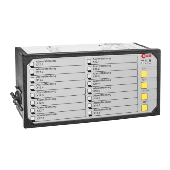
Functional description 3.8 Labelling Labelling of the annunciators is done by means of designation strips that can be inserted beneath the cover foil after removing the front frame. The designation strips with signal names can be created and printed directly from the parameterization interface on the web-server or generated manually from labelling strips in Word- format. - Page 17 Table 3.1: Indication of alternative operating states of the USM by green flashing of the Watchdog LED "OK" During the initialisation process of the fault indicator after the restart, the three control lamps "OK", "S1" and "S2" light up green several times in succession.
- Page 18 - Rx serial interface [18] LAN connection (Ethernet / RJ45, optional) [19] Connection for ground potential On the USM 08, terminal X11 (function inputs) is not located under terminal X12, but under terminal X10. Page 18 of 72 MSM-USM2G-BA-UK-004...
-
Page 19: Diagnosis
- No power supply With the USM, an error code can be derived from the blink sequence and the associated error can be inferred. A flashing sequence consists of: Number of long flashing pulses 1st digit of the error code ... - Page 20 The downloaded CID-file is incorrect. Please download the Faulty CID-file correct CID-file to the device. Extension address In cascaded systems incorrect The slave generates the error when it is set to address "0". Table 3.2-1: Error code of the USM part 1 Page 20 of 72 MSM-USM2G-BA-UK-004...
- Page 21 IEC 104 Client connection not send any data. Ethernet connection 1 (X8) Ethernet connection faulty - Check the Ethernet cable at the USM Ethernet connection 2 (X98) and the remote terminal (switch). The IEC server can be reached by the client, but the general IEC104 Client GA interrogation returns incomplete data.
-
Page 22: Terminal Assignments
Functional description 3.11 Terminal assignments Fig. 3.9: Terminal assignments of the USM Page 22 of 72 MSM-USM2G-BA-UK-004... - Page 23 Functional description Detailed terminal assignments Function inputs (X11) Signal inputs (X10, X12, X14, X16, X18, X20) Fig. 3.10: Terminal assignment of the function inputs Fig.3.11: Terminal assignment of the signal inputs Optionally, additional cards can be integrated in the versions 4 analog inputs and 8 relay outputs. Analog input cards have blue terminals for better differentiation.
- Page 24 Functional description Connection variants of the sensors to analog inputs Depending on the task and local circumstances, the following connection variants can be selected: Fig. 3.14 Potential-separated sensors Fig. 3.15: Sensors with common reference ground (Ground connected to sensor) Fig. 3.16 Sensors with common reference ground Fig.
-
Page 25: Front And Back Views Of The Usm
For units which do not have these options, the corresponding terminals are omitted. Fig. 3.18: Front- und Back view of the USM 08 3.12.2 USM 16 Fig. 3.19: Front- and back view of the USM 16 in housing 96 x 96... -
Page 26: Usm 16 In Wide Housing
Functional description 3.12.3 USM 16 in wide housing Fig. 3.20: Front view of the USM 16W in wide housing 96 x 192 Fig. 3.21: Back view of the USM 16W in wide housing 96 x 192 Page 26 of 72... -
Page 27: Usm 24
Functional description 3.12.4 USM 24 Fig. 3.22: Front view of the USM 24 Fig. 3.23: Back view of the USM 24... -
Page 28: Usm 32
Functional description 3.12.5 USM 32 Fig. 3.24: Front view des USM 32 Fig. 3.25: Back view of the USM 32 Page 28 of 72 MSM-USM2G-BA-UK-004... -
Page 29: Usm 40
Functional description 3.12.6 USM 40 Fig. 3.26: Front view of the USM 40 Fig. 3.27: Back view of the USM 40... -
Page 30: Usm 48
Functional description 3.12.7 USM 48 Fig. 3.28: Front view of the USM 48 Fig. 3.29: Back view of the USM 48 Page 30 of 72 MSM-USM2G-BA-UK-004... -
Page 31: Input And Led Assignment
In the following example, this is X14.1. The other assignments of the input terminals are as shown in the individual alarm labels on the front panel in the drawing below. Fig. 3.30: Assignment between alarm input and LED display using the example of a USM 24... -
Page 32: Technical Data
37…73 V DC or 26…51 V AC 48 V AC/DC or 60 V DC 85…370 V DC or 85…264 V AC 110 V AC/DC or 220 V AC/DC Table 3.3: Supply voltage keys - USM Signal voltage U Threshold for alarm Maximum... - Page 33 < 11 < 24 < 8 < 13 < 12 < 17 Table 3.5: Power consumption - USM General data Buffer time in the event of failure / short circuit 100 ms Response delay adjustable (0 … 1000 ms), factory setting 5 ms (flutter suppression) adjustable (5 ms …...
- Page 34 Functional description Environmental conditions Operating ambient temperatu -20°C ..+60°C Storage temperature -20°C ..+70°C Duty cycle 100 % Protection class at the front IP 54 Protection class in the back IP 20 Humidity 75% r.h. max. on average over the year; up to 93% r.h.
-
Page 35: Mounting And Intallastion
5. For a cascaded annunciator system, connect slave devices according to steps 2 and 3 and connect the cascaded annunciator to each other by means of a patch cable through the CAN- Bus-interfaces (terminal X7 at the USM and terminals X7/X8 at the BSM). 6. Connect the power supply and activate power supply. -
Page 36: Parameterization
5 Parameterization The parameterization of the USM is done through the integrated web-server by means of a web- browser. For access to the web-server, the network interface (terminal X8) of the USM has to be connected to the PC. System requirements ... - Page 37 Parameterization After logging in, the following page opens up: Fig. 5.2: Start page of the USM web server, tab reporting channel The menu bar next to the EES logo contains the four main menus: Language Information Parameter ...
- Page 38 Parameterization Below the main menu bar the menu path and the user are displayed. In the main part of the page, the "Parameters/Devices/Master device" menu is already open. It would be possible to start immediately with the parameterization of the fault message functionality of the basic device.
-
Page 39: Main Menu Language
The menu is structured into sub-menus by 4 tabs: 1. Sub-menu Device information This page displays information on the software status of the individual program components of the USM. 2. Sub-menu Documentation Here the device documentation in PDF-format can be found. -
Page 40: Main Menu Parameter
IEC 60870-5-101/104 Modbus EES factory defaults Resets all parameterized devices (also slave devices) to factory settings. The factory setting must then be saved in the devices with the function "Accept configuration" (only Master device) or "Accept all 4 configurations" (Master device and all Slave devices). -
Page 41: Menu Device Administration
5.3.1.1 Submenu New/adapt The cascading function can be used to form an annunciator system from one USM and up to 3 BSM-C or BSM-P, which has common annunciation processing (annunciation sequence, collective annunciation formation and horn control). The alarms of the entire cascaded annunciator system can be accessed via the interface of a USM, for example. - Page 42 Parameterization Fig. 5.7: Submenu New/adapt After selecting the desired fault annunciator from the list, the device is automatically created and appears under the name Slave device 1 to Slave device 3 in the main menu "Parameters". The menu of a newly created slave annunciator corresponds to the menu of the master device. However, the "Reporting sequence"...
-
Page 43: Submenu Export/Import
Parameterization 5.3.1.2 Submenu Export/Import On this page, the configuration of the fault annunciator(s) can be stored or a parameter file can be loaded. The following options are available: Store complete parameterisation The parameters of the whole annunciator system (incl. optionally connected slave devices in a cascaded system) are packed to one file and saved. -
Page 44: Menu System
Fig. 5.10: Submenu Time Manual time synchronisation With click on the button “set time”, the manually entered time is sent to the USM. With click on the button “set actual time”, the PC time is sent to the USM. Synchronisation by NTP For time synchronisation two alternative NTP-server can be used. -
Page 45: Submenu Security / Passwords
Parameterization Please note that activation of a new IP address with „accept configuration“ will interrupt the connection to the fault annunciator. The connection has to be reestablished with the new IP address. Subnet mask Please enter the subnet mask for the network used. Gateway IP Address If the network communication is realised through more complex structures (e.g. - Page 46 Parameterization In this menu the handling of device errors can be defined. Blinkcode and description The entries in this field cannot be edited and show the blinkcode and the corresponding error in clear text. The first 20 entries are device errors and can be displayed with the blinkcode by the Watchdog LED „Self-monitoring“.
-
Page 47: Submenu Serial
The serial interface on the 2nd interface card terminal X96 can be switched between RS232 and RS485. 5.3.2.6 Submenu Firmware If a firmware update is required for the USM, the respective firmware file can be uploaded into the device on this page. 5.3.2.7 Submenu Licences The USM provides communication through the protocol IEC 60870-5-101/104 by default. -
Page 48: Menu Master-Device / Slave-Device1
Parameterization 5.3.3 Menu Master-device / Slave-device1..3 In the menu “Master-device” or “Slave-device1..3”, respectively, the fault annunciation functionalities of the device can be parameterized. This menu contains the following sub-menus: Reporting channel Reporting sequence (only available for Master-device) Buttons &... - Page 49 Parameterization In the table the following parameters can be defined for each signal channel: Field name Explanation Channel number (firmly specified) Input terminal (firmly specified) Designation of the respective channel Signal name This designation will be used when printing the labelling strips. A 2-line labelling can be realised by separating the second line by “\”...
- Page 50 Parameterization Field name Explanation CR1, CR2, Assignment to collective reports If one of these check boxes is activated, the alarm triggers the corresponding collective alarm. Multiple assignments or none are possible. All alarms assigned to a collective alarm form a group. This assignment is also important for alarm acknowledgement and RESET.
- Page 51 Parameterization Response delay (debounce time) Closing a contact may cause several edge changes before the contact is permanently closed. Due to the short response time when detecting alarms, several alarms could therefore be generated during the closing of the contact. To prevent this, the response delay (debounce time) can be set in 1 ms steps up to a time of 1000 ms.
-
Page 52: Submenu "Reporting Sequence" (Only Master Device)
Parameterization For device and channel designation, all characters from A…Z and 0…9 are allowed. The special characters „ { } | $ & # ; “ are not allowed. For channel designations, „\“ (backslash) is used as separation mark to start a new line. 5.3.3.2 Submenu “Reporting sequence”... - Page 53 Parameterization Reporting sequence Designation Selection options Note 1-Frequency 1- Frequency flashing light 2-Frequency 2- Frequency flashing light Signaling Self-clearing alarm: Alarm is immediately displayed State display as an acknowledged alarm and goes when the associated input is no longer present. New value New value alarm Reporting...
-
Page 54: Submenu Buttons And Function Inputs
Parameterization Horn Designation Selection options Note The internal and external horns are controlled in Activated parallel. Internal horn active The internal horn is switched off, the horn contact Deactivated for connecting the external horn is still active. The alarms can be acknowledged according to the Inactive Horn activation setting of the "Reporting channels"... - Page 55 Parameterization Function Meaning Acknowledge 1, 2, 3, Acknowledgement optical for alarms of groups 1, 2 ,3 or unassigned unassigned alarms Reset 1, 2, 3, unassigned Reset for alarms of the collective alarm groups 1, 2 or 3 or unassigned alarms (only needed when 2-frequency reporting sequence is activated) Horn Acknowledgement acoustic (horn)
-
Page 56: Submenu Relays (Function Relays)
Parameterization 5.3.3.4 Submenu Relays (function relays) In this submenu, the assignment of the 4 function relays to the individual fault alarm functions, buttons or function inputs takes place. Several events can be defined for a relay, e.g. the grouping of collective alarms. -
Page 57: Submenu Repeat Relays
Parameterization 5.3.3.5 Submenu Repeat relays Fig. 5.19: Submenu Repeat relays The optionally available relay cards (with 8 NO contacts each) are independent of the 4 function relays described in the previous section. During parameterization, only the relay groups available in each case are displayed. -
Page 58: Submenu Led Colour Settings
On this page the LED colours for the operation modes “operation indication” and “fault annunciation” of each channel can be defined. The USM is supplied with DUO LED or RGB LED. The basic parameterization of the colour setting is the same. The variants differ only in the selectable colours:... -
Page 59: Submenu Analog Channels
5.3.3.7 Submenu Analog channels Depending on the size of the device, a USM can be equipped with up to 5 analog input cards. Each input card has 4 analog inputs. The submenu is only displayed if analog cards are integrated in the fault indicator. - Page 60 Parameterization Dialog Reports Parameter Interpretation Terminal of the analog value Signalname The signal name consisting of ASCII characters is used to identify the value and is “Main menu also displayed in the diagnostic monitor (see section Monitor”). Measuring The inputs can be configured as voltage or current inputs depending on the mode application.
- Page 61 Parameterization Dialog Adjustment Fig. 5.22: Submenu analog channels - Dialog adaption The measured value acquisition has an accuracy of better than 0.5% when delivered. If it is necessary to adapt the measured value acquisition, e.g. for a lead adjustment of the sensor, it can be readjusted via two parameters.
- Page 62 Parameterization Dialog Sensor Fig. 5.23: Submenu analog channels - Dialog Sensor This dialog is used to parameterize the display of the analog values in the main menu "Monitor". The first 5 columns are taken from the previous dialog, but they can be changed. Parameter Meaning Sensor display...
-
Page 63: Main Menu Monitor
Parameterization 5.4 Main menu Monitor The monitor is a diagnostic tool for the USM and any slave devices connected in the cascade. In this representation, the LED of the fault indicator is shown with its states (flashing, on and off). -
Page 64: Reset To Factory Settings
Excel-files (e.g. data point lists). In this case it is useful to transfer this information to a template and import it into the annunciator. EES provides a template that can be filled in and processed with common procedures. With the Excel file the parameters for the alarm channels, repeat relays and IEC objects can be imported into the WAP. -
Page 65: Alarm Channels And Iec Objects
Parameterization The Excel-file has to be of the type .xls, other Excel formats cannot be processed by the annunciator. 6.1 Alarm channels and IEC objects The name of the tab „EES_Input“ must not be changed, otherwise the tab will not be processed during the import. -
Page 66: Iec-Objects Of The Reporting Channels
Parameterization Delay times / Defluttering „debounce time“ 0 – 1000 ms „response delay“ delay time from 0ms .. 32400s (9h), up to 30s in pattern of 1ms, any longer times in pattern of 1s. Format: mmm:ss.xxx (xxx indicates the value of the milliseconds). If no delimiters are used, the entered value will be interpreted in seconds. -
Page 67: Iec Objects And Repeat Relays
Parameterization Object types Two object groups are available for communication as IEC server (station) and IEC client (Master). Object types server communication: Input (undelayed) - physical activation of the signal input Delayed Input - signal input after expiration of the response delay Unacknowledged Alarm - alarm at issue/receded (stored, but not acknowledged) Stored Alarm... -
Page 68: Iec-Objects Of The Repeat Relays
Parameterization 6.2.2 IEC-objects of the repeat relays For each repeat relay and IEC type, an IEC object is generated. All objects are formed identically and have the same parameters. Discrete object parameters „ASDU“ - integer value 0 – 65535 or structured xx-xx (e.g. 11-22). „IOA“... -
Page 69: Simple Logic Function
Parameterization 6.3 Simple logic function With the tab EES_Collective a simple logic disjunction for up to 16 alarms, which are formed out of OR-disjunctions of multiple inputs, can be parameterized. The designations in line 2 are mandatory for correct import of the Excel file. Index (idx) Index of the collective report or disjunction, respectively, 1 –... -
Page 70: Use And Product Life Cycle
+ 49 (0) 7191/182-0 Fax: +49 (0) 7191/182-200 E-Mail: info@ees-online.de 7.3 Shutdown In the event of temporary or permanent decommissioning of the product, proceed according to the instructions below. These may only be carried out by trained specialist personnel. Improperly performed activities can lead to partial or complete failure of the product. -
Page 71: Packaging And Transport
Contact Contact Elektra Elektronik GmbH & Co Störcontroller KG Hummelbühl 7-7/1 71522 Backnang Germany Tel.: +49 (0) 7191/182-0 Fax: +49 (0) 7191/182-200 E-Mail: info@ees-online.de Internet: www.ees-online.de Tel.: +49 (0) 7191/182-0 Fax: +49 (0) 7191/182-200 E-Mail: info@ees-online.de Internet: www.ees-...
Need help?
Do you have a question about the USM and is the answer not in the manual?
Questions and answers