
Summary of Contents for OLIJU IMTP 2.2 M-RS
- Page 1 Motor Pump Inverter Type IMTP 2.2 M-RS ITTP 2.2 M-RS ITTP 4 M/W-RS ITTP 5.5 M/W-RS ITTP 7.5 W-RS ENG - Operation and maintenance handbook...
-
Page 2: Table Of Contents
INDEX SPECIFICATIONS ........................ 3 WORKING OPERATIONS ...................... 3 2.1 STRUCTURE OF A FREQUENCY CONVERTER .............. 3 WORKING CONDITIONS ...................... 4 WARNINGS AND RISKS ...................... 4 5. ASSEMBLING AND INSTALLATION .................... 5 5.1 Fixing measures ........................ 5 Pump hydraulic connection .................... 6 Electric connections ...................... 6 5.4 Motor-pumps phases connection .................. 6 Electric connection to Line and Motor ................ 7 Pressure transducer connection, on different types ............ 8 5.7 Connections on the electronic board ................. 9 STARTING AND PROGRAMMING .................. 12 6.1 First Inverter Using Ð Self Regulation procedure ............. -
Page 3: Specifications
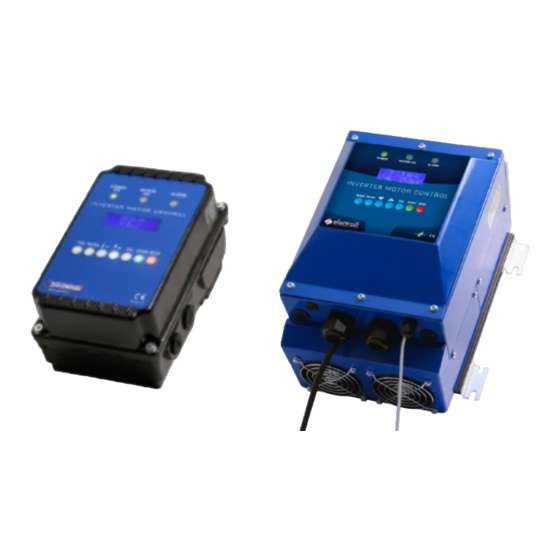
SPECIFICATIONS With this manual, we would like to give you the most important information about the correct use and maintenance of the inverter. The devices described in this manual are: § IMTP2.2M-RS: Single-phase Inverter for motor pump, max 2.2 kW (3 Hp) § ITTP2.2M-RS: Three-phase Inverter for motor pump, max 2.2 kW (3 Hp) § ITTP4.0M/W-RS: Three-phase Inverter for motor pump, max 4 kW (5.5 Hp) § ITTP5.5M/W-RS: Three-phase Inverter for motor pump, max 5.5 kW (7.5 Hp) § ITTP7.5W-RS: Three-phase Inverter for motor pump, max 7.5 kW (10 Hp) This inverters are devices specially designed for pump motor control, thanks to a perfect feed-back pressure: it assures a good energy saving and it has many programmable functions, that are not in the other common directly supplied motor pumps. -
Page 4: Working Conditions
3. WORKING CONDITIONS Quantity Simbol Meas. IMTP ITTP ITTP ITTP ITTP Unit Ambient working temperature ¡C 0..40 Maximum relative humidity (40¡C) Protection grade of the Inverter IP55 Nominal pump power connected to 2.2 2.2 4.0 5.5 7.5 the Inverter 5.5 7.5 Nominal voltage supply of the Inverter 100..244 200..460 200..460 200..460 200..460 Frequency supply Inverter 50-60 Voltage Inverter output Fequency Inverter Output 0..55 Nominal input current Nominal output current (to motor) 9.5... -
Page 5: Assembling And Installation
IMTP2.2: EMC single-phase filter common mode single-stage, 250V Ð 10A: L: 2x 2.2 mH ; · : 0.47 F; · C :2x25 nF. · C ITTP2.2: EMC three-phase filter common mode single-stage, 440V Ð 10A: L: 3x 0,12 mH; · : 3x0,1 mF; · C : 22 nF. · C ITTP5.5/7.5: EMC three-phase filter common mode single-stage, 440V Ð 20A: L: 3x 0,12 mH; · : 3x0,1 mF; C : 22 nF. · C The installer has to be careful connecting the ground wire directly to the inverter frame (an eyelet terminal is preferred; for having a good contact it is important to remove the paint from the contact surface). It is necessary to avoid ground loop, that is like an antenna for EMC emission. Power supply must be admitted on working condition; donÕt lift or carry the motor pump (or the motor connected to the inverter) lifting it from the inverter. -
Page 6: Pump Hydraulic Connection
Pump hydraulic connection Connect the hydraulics according to the regulations in force. This product can work when connected to the waterworks or taking water from a water cistern. If you connect the system to the waterworks, you have to respect the regulations in force issued by local authority (Common, local authority, etcÉ). It is important to put a pressure switch on the inlet leader; it switches off the motor power in case of low pressure (it is a dry-working external protection). The inverter have two ports for a normally-closed generic contact: EN and C on the logic board (fig. 4). Verify the amount of pressure between the waterworks and the maximum pump pressure, does not exceed the maximum pump pressure value (nominal pressure) Besides, it is important to put a pressure gauge on the outlet leader, so it is possible to regulate the pressure factory setting value, according to the real conditions of the system. On the outlet leader it is necessary to install a pressure gauge with an output signal between 0 – 5 Vdc or 4 – 20 mA; this signal is an input to the inverter. As a rule it would be better to install flexible or rigid pipes on inlet and outlet branches, on-off valves on inlet and outlet branches, a no return valve, a membrane surge tank. To avoid drying the system for replacement of the membrane surge tank, pressure gauge or pressure transducer, it would be better to install some on-off valves... -
Page 7: Electric Connection To Line And Motor
The three-phase inverters ITTP2.2 and ITTP5.5/7.5 must be installed on asynchronous three-phase motor with 200-460 Vac 50/60 Hz voltage supply. The phases must be connected in star mode if the motor is 230V / 400 V (most common case, as in Fig 4). Figure 4 – Star motor phases connection The unit is equipped with output over-current protection; it is not necessary to install any additional safety device between the inverter and the pump in order to protect the motor in case of failure. -
Page 8: Pressure Transducer Connection, On Different Types
§ Optional 4 - only for IMTP-ITTP2.2: flow switch connection to detect the minimum flow stop in mechanical mode: connect the two terminals of the flow switch on +15V (1 of J8, fig. 5) and PS2 (3 of J8, fig.5) on the Logic board; the two contact can be inverted; § Optional 5: for IMTP-ITTP2.2 there is relay output contact (1, 4 of J11 fig.5, MOT.ON-COM) 2Ampere Ð 250Vac max. that close when the motor is working; for ITTP4.0-5.5-7.5 between contacts MOTOR ON and ÒÐÒ of J10 (fig.8) there is a 12Vdc 200mA max. signal when the Motor is working; § Optional 6: for IMTP-ITTP2.2 there is relay output contact (2, 4 of J11, ALARM-COM, fig.5) 2Ampere Ð 250Vac max. that close when there is an Alarm condition; for ITTP4.0-5.5-7.5 between contacts ALARM and ÒÐÒ of J10 (fig.8) there is a 12Vdc 200mA max. signal when there is an Alarm;... -
Page 9: Connections On The Electronic Board
Connections on the electronic board Figure 5: Logic board of IMTP2.2-ITTP 2.2 IMTP 2.2 - ITTP 2.2/4/5.5/7.5... - Page 10 Figure 6: Power board of IMTP 2.2 Figure 7: Power board of ITTP 2.2 IMTP 2.2 - ITTP 2.2/4/5.5/7.5...
- Page 11 Figure 8: Logic board of ITTP 4/../7.5 Figure 9: Power board of ITTP 4/../7.5 IMTP 2.2 - ITTP 2.2/4/5.5/7.5...
-
Page 12: Starting And Programming
6. STARTING AND PROGRAMMING The starting and programming operations must be executed exclusively by experienced and qualified staff. Use the appropriate equipment and protections. To supply voltage on the Inverter verify that the Inverter box is completely closed, after having carefully followed all the instructions wiring above. The pump can not run dry; functioning under these conditions (even for a short time) irreparably damage the pump itself. For this the control system intervenes after about a minute (usually sufficient time for water loading pump during the initial service) with an alarm, stopping the pump as described in Chapter 2. -
Page 13: Programming Functions
6.3 Programming Functions Display: · Figure 10: Display data · List of command on the control panel Command Description FUN / MODE To enter on main functions menu ENTER To enter on the function and modify the values It allows scrolling up the items on the menu or positive change in the value of variables; + after the variation press ENTER. Encrease the reference pressure during functioning. - It allows scrolling down the items on the menu or negative change in the value of variables; after the variation press ENTER. Decrease the reference pressure during functioning. To exit to the function and automatically saving ESC Pump start START Pump stop; If pressed with the key Ò-Ò during 5 seconds do a RESET. STOP Table 5: List of commands on the control panel ·... - Page 14 FUNCTIONS MENU DESCRIPTION · Main Menu Submenu Description Italian Insert language for display command Lingua/Language English showing. Spanish Default: Italian Day Allow to do the data regulation (day Ð Month month Ð year) and the time (hour Ð minute Year Ð second). It Is important to set in following Date adjurnment Hour conditions: Minute · Single Pump with programming; Second · Group of pumps Master-Slave. Pressure followed in feedback through pressure sensor. Reference pressure The same parameter can change directly Reference Pressure [X.X BAR] during pump functioning, pushing Ò+Ó or Ò-Ò on the control panel. Default: 3.0 BAR Set the motor current reading by motor rating data, according to the motor phases connection in use (star/triangle, see 5.3).
- Page 15 Sub-menu ADVANCED Description FUNCTIONS MENU ADVANCED FUNCTIONS Programs: P1 (start 1) Select Start Prog. ON or OFF. A1 (stop 1) Start and Stops in this format: Programming É Day : Month Ð Hour : Minute P7 (start 7) A7 (stop 7) 1. Nominal Voltage [V] 1. Nominal motor Voltage Ð Default: 230V for IMTP2.2; 400V for ITTP2.2/../7.5; 2. Nominal frequency [Hz] 2. Nominal Motor frequency Ð Default: 50Hz; 3. Maximum velocity [%] 3. Maximum Motor Velocity Ð Default: 102%; Motor Limits 4. Minimum Motor Velocity 4. Minimum velocity [%] 5. Motor acceleration 5. Acceleration [RPM/s] 6. Maximum Motor current limitÐ Default: 105% Values % on respect the nominal values 6. Maximum current [%] 1. Pressure control hysteresis- Default: 0.30 BAR;...
-
Page 16: Alarms
Alarms Alarm Alarm Type Description Number Current Peak Immediately stop probably caused by short-circuit Automatic re-start; final stop after 10 consecutive events Over-Voltage Normally caused by over voltage pick supply. Automatic re-start; final stop after 10 consecutive events Inverter Temperature Over temperature IGBT protection (90¡C) Automatic re-start; final stop after 10 consecutive events T exceeded Motor thermal protection related to nominal current set, for motor insulations saving at high temperatures. Automatic re-start; final stop after 10 consecutive events Dry working Null input flow or air presence; Automatic re-start; final stop after 5 consecutive events Pressure sensor problem Pressure sensor output problem Automatic re-start; final stop after 10 consecutive events The pump stop for minimum flow limit achievement. It’s a normal Minimum flow working condition of the system (no demand of water on the delivery) even thug is on the alarm list, Automatic re-start; no limits Enable OFF Open contact between EN e C (figure 5 e 8): stop the motor; the motor restart when the contact will close again The microprocessor temperature exceed a limit value, then the system Over-temperature must stop until the temperature return low. -
Page 17: Replacing The Battery
6.6 Replacing the battery The lithium battery CR2032 for IMTP-ITTP2.2 and CR2430 for ITTP4/../7.5 are used exclusively for storing date and time even in the absence of power supply for a long time (the battery can live 4-6 years without inverter power supply). The lithium battery should be replaced when the user notice that the inverter does not maintain stored date and hour in the absence of power supply. NOTE: Even with exhausted or absent lithium battery remain stored all inverter functional settings indefinitely. To replacing the lithium battery it needs: 1. Disconnect the power cable from the line; 2. Open the inverter box unscrewing the No. 4 screws; 3. Wait for the complete shutdown of the led which indicates the charge of capacitors before touching any part of electronic boards; 4. Replace the battery present under the cover of the inverter. 7. SOLUTION OF THE MOST COMMON PROBLEMS N°... -
Page 18: Guarantee
The Inverter stop the motor for A small water membrane Tank charged with 1.5-2 Bar air pressure is required for a Minimum Flow with a high flow correct working; check it. condition and then re-start and The condition may also caused by a not correct pump curve saving during the stop again, continuously automatic check: possibly the delivery was not totally closed and the Inverter checked a higher curve of the pump; repeat the automatic check (Pump data -> check ON, then exit to the menu and press START) closing totally the outlet and try again the functioning. Verify if there is a no-return inlet valve on the pump and if itÕs working good without loses. ItÕs possible to reduce the flow before stopping reducing the parameter F1 ItÕs possible to reduce the flow before stopping reducing the parameter Minimum Flow Power stop % on Motor Data. The inverter donÕt switch off the Probably check was done with pump not perfectly filled up; remake the check pump when the valve on procedure after a complete filling of the pump and try again if pump switch off correctly delivery is totally closed in minimum flow condition. If the problem remain, try to grow up the function: Advanced Functions -> Motor data -> Minimum flow power stop, upgrading 2% every time and testing pump, till find the correct working. The hydraulic system have a big Probably during the automatic check there was a flow of water to full up the big tank, tank (>40 l) and, after check did for that the pump curve saved by the inverter is not the correct curve (with null flow correctly with closed delivery, and maximum pressure). the pump stop for minimum flow Maintain full of water the tank (pressure near maximum value); repeat the automatic with a high flow, and then re- check (Pump data -> check ON, then exit to the menu and press START). When the start and stop again, check finish try to work again testing the minimum flow stop condition of the motor that continuously must be with a small flow. The Inverter stop the motor for Sometimes the problem is caused by the same Automatic Check error that previous Dry Working condition point (see possible solution like above). -
Page 19: Dichiarazione Di Conformitaõ / Declaration Of Conformity
DICHIARAZIONE DI CONFORMITA’ / DECLARATION OF CONFORMITY dichiara che i prodotti Inverter elencati / declare that the products: IMTP2.2M-RS; ITTP2.2M-RS; ITTP4.0M/W-RS; ITTP5.5M/W-RS; ITTP7.5W-RS; Sono conformi alle disposizioni delle seguenti direttive europee e alle disposizioni nazionali di attuazione in base alle seguenti norme tecniche / Are conform to the following European directives and to national law following the technical standards: Machines 98/37/CE ·... - Page 20 OLIJU Comercial OLIJU Manufacturing Avenida Santiago, N.º 43 Rua do Campo Grande, nº 15 Zona Industrial de Rio Meão Zona Ind. Esmoriz - Sector C 4520-475 Rio Meão 3885-530 Esmoriz PORTUGAL PORTUGAL GPS: GPS: 40º57'37.20"N 40º57'27.11"N 8º35'50.10"O 8º36'13.86"O +351.256.780910 oliju@oliju.com http://www.oliju.com...
Need help?
Do you have a question about the IMTP 2.2 M-RS and is the answer not in the manual?
Questions and answers