Advertisement
Quick Links
Advertisement

Related Manuals for YoraHome MANDRILL 3036

Summary of Contents for YoraHome MANDRILL 3036
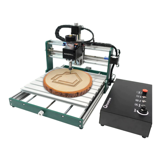
- Page 1 YORA MANDRILL 3036 CNC ROUTER USER MANUAL Version 1.0 • February, 2022...
- Page 2 Purpose This Manual is intended for assembly of the Yora Mandrill 3036 CNC Router. This manual is designed to cover the basic functionality of the machine and software, and may not address every aspect or option present. Before beginning assembly, we recommend conducting an inventory using the Packing List to ensure all components are present.
- Page 3 ➔ Read and understand the entire user manual before attempting assembly or operation ➔ Do not use the CNC router for other than its intended use. If used for other purposes, YoraHome disclaims any real or implied warranty and holds itself harmless from any injury that may result from that use.
- Page 4 Safety ➔ Make certain the switch is in the OFF position before connecting CNC router machine to the power supply ➔ Make all machine adjustments or maintenance with CNC router unplugged from the power source. ➔ Give your work undivided attention. Looking around, carrying on a conversation and “horseplay” are careless acts that can result in serious injury.
- Page 5 Safety ➔ Always secure workpiece to spoil board using clamps or double-sided tape. Never hold workpiece down by hand while operating. ➔ Make sure workpiece is free from nails or other foreign objects. ➔ After installing a bit, make sure collet is securely tightened. An unsecured bit may fly loose from the collet and cause injury.
-
Page 6: Table Of Contents
Contents Part 1: Packing List Part 2: Mechanical Assembly Part 3: Software Installation Part 4: Machine Setup Part 5: Recommended Settings Part 6: Optional Laser Part 7: Best Practices Part 8: Terminology... -
Page 7: Part 1: Packing List
Part 1 Packing List Item Size Picture Quantity Mandrill Controller... - Page 8 Part 1 Packing List Item Size Picture Quantity Z/X Axis Assembly Base/Y Axis Assembly...
- Page 9 Part 1 Packing List Item Size Picture Quantity Spindle Motor Laser Adapter Sleeve Drag Chain Bracket Drag Chain/Wire Harness Assembly...
- Page 10 Part 1 Packing List Item Size Picture Quantity M5 x 8mm M4 x 10mm Socket Head Cap Screws M3 x 6mm (Countersunk) M4 x 8mm (Countersunk) Square Nut...
- Page 11 Part 1 Packing List Hardware Box - continued Item Size Picture Quantity Hold-down Clamps Including M5 bolts M5; including wing nuts and Clamp Thumbscrews washers 13mm x 15mm Wrenches 14mm x 17mm Z Probe Assembly 20mm...
- Page 12 Part 1 Packing List Hardware Box - continued Item Size Picture Quantity Hex Key 2mm, 2.5mm, 3mm, 4mm 1 of each Power Cable USB Cable...
- Page 13 Part 1 Packing List Hardware Box - continued Item Size Picture Quantity 0.8/1.0/1.2/1.4/1.6/1.8/2.0/2.2/ Shank Blue Corn Milling Bits 1 pack of 10 2.4/3.17 mm Engraving Bits 30 deg bit, 0.1mm cutting tip 1 pack of 10...
- Page 14 Part 2 Mechanical Assembly Step 1 - Assemble Base & Z/X Assembly Parts Required: ➔ 8 M5 x 8mm Screws...
- Page 15 Part 2 Mechanical Assembly Step 1 - Assemble Main Frame ➔ Place the Base Assembly on a flat level surface On either side of the Base Assembly, space the 4 captive nuts so that they are easily accessible. Exact positioning is not critical, this will be adjusted in a later step.
-
Page 16: Part 2: Mechanical Assembly
Part 2 Mechanical Assembly Step 1 - Assemble Main Frame ➔ Carefully place the Z/X Assembly over the Base Assembly - ensuring that the Y Axis motor on the Base is OPPOSITE the Spindle Motor. ➔ Fasten the Z/X Assembly to the Base Assembly with the M5 x 8 screws NOTE - Do NOT tighten the screws... - Page 17 Part 2 Mechanical Assembly Step 1 - Assemble Main Frame Adjust the Z/X Assembly so that the rear edge of the mounting plate is 5-½ inches from the rear edge of the Base Assembly; and tighten the M5x8mm mounting screws. NOTE - Check the adjustment on both sides of the machine before tightening the screws.
- Page 18 Part 2 Mechanical Assembly Step 2 - Install Drag Chain Bracket Parts Required: ➔ 2 M4 x 10mm Screws ➔ Drag Chain Bracket Install the Drag Chain Bracket to the rear of the Z Axis assembly, as shown.
- Page 19 Part 2 Mechanical Assembly Step 3 - Install Drag Chain/Wire Harness Parts Required: - 2 Countersunk M4 x 8mm Screws - 2 Countersunk M3 x 6mm Screws - 2 M4 Square Nuts - Drag Chain/Wire Harness Assembly Lay out the Drag Chain/Wire Harness Assembly on the table to prepare the end for installation.
- Page 20 Part 2 Mechanical Assembly Step 3 - Install Drag Chain/Wire Harness Using the Countersunk M4 x 8mm Screws and M4 Square Nuts, install the screws and nuts as shown below in preparation for installation on the top rail. Do NOT tighten the screws at this time.
- Page 21 Part 2 Mechanical Assembly Step 3 - Install Drag Chain/Wire Harness Lay the Drag Chain on the top rail of the Mandrill as shown. The M4 Square Nuts will fit into the open channel on the rail. Using the appropriate hex key, tighten the 2 screws to attach the end of the drag chain to the rail, above the X Axis motor.
- Page 22 Part 2 Mechanical Assembly Step 3 - Install Drag Chain/Wire Harness Bring the other end of the Drag Chain in a loop, aligning the end of the Drag Chain with the previously installed bracket. Using the Countersunk M3 x 6mm Screws, attach the end of the Drag Chain to the Drag Chain Bracket at the rear of the Z/X Axis Assembly...
- Page 23 Part 2 Mechanical Assembly Step 4 - Install Spindle Motor Carefully slide the Spindle Motor into the bracket on the Mandrill. NOTE - Do not allow the Spindle Motor to “drop” into the bracket; damage to the motor brush holders may result.
- Page 24 Part 2 Mechanical Assembly Step 4 - Install Spindle Motor Using the appropriate hex key, tighten the screws on the Spindle Motor bracket to secure the motor. These do not need to be tightened to the point that the gap in the bracket is closed; tighten only to the point that the Spindle Motor cannot be raised or twisted by hand.
- Page 25 Part 2 Mechanical Assembly Step 5 - Install Wiring Connections Right end of X Axis Assembly: - X Motor - X Limit...
- Page 26 Part 2 Mechanical Assembly Step 5 - Install Wiring Connections Rear of Base Assembly: - Y Motor - Y Limit...
- Page 27 Part 2 Mechanical Assembly Step 5 - Install Wiring Connections Top of Z/X Axis Assembly: - Z Limit - Z Motor...
- Page 28 Part 2 Mechanical Assembly Step 5 - Install Wiring Connections Front of Z/X Assembly: - Spindle Motor Match Positive (+) and Negative (-) terminals to ensure proper rotation.
- Page 29 Part 2 Mechanical Assembly Step 5 - Install Wiring Connections Rear of controller: - Axis Motors - Spindle - Limit Switches All connections are indexed for proper insertion. Ensure the Laser/Spindle switch is in the “Spindle” position. Plug in power cord and turn power switch on. Twist the Emergency Stop switch clockwise to reset - will not connect when depressed!
- Page 30 Part 2 Mechanical Assembly Step 6 - Accessory Installation Using the included Laser Adapter Sleeve, the Mandrill holder can also accommodate the laser accessory. The Yora Diode Laser Modules are available separately: https://yorahome.com/products /yora-laser-module...
- Page 31 NOTE FOR MAC USERS: If your Mac is running Mojave OS or higher, do NOT install the driver, as the OS has native support for the CH340. If you are running Sierra or High Sierra, please contact YoraHome Technical Support for additional guidance.
-
Page 32: Part 3: Software Installation
Part 3 Software Installation Step 2 - Determine your machine COM’s port (Windows computers) • Windows XP: Right click on My Computer, select Manage, then Device Manager. • Windows 7: Click on Start on the taskbar, right click on Computer, select Manage, then Device Manager. •... - Page 33 Part 3 Software Installation Step 3 - Log into Easel We recommend that our customers use a web application called Easel, which is developed by Inventables for their X-carve machines. It works great with the the SilverBack too. It is free (the pro version is not really needed), powerful and easy to use to design and carve your projects.
- Page 34 Part 3 Software Installation Step 4 - Create your account in Easel • Click on the “Create New Account” option • Enter your personal information • When you are done, click on the orange Start Free Trial button NOTE - Inventables defaults all new accounts to a free 30-day trial of Easel Pro.
- Page 35 Part 4 Machine Setup Step 1 - Your first project in Easel! Create a new project by selecting one document in the Projects tab (it can be “Intro to Easel” or any “Untitled”)
- Page 36 Part 4 Machine Setup Step 2 - Easel driver: Click on the blue Carve button.
- Page 37 Part 4 Machine Setup Step 3 - Easel driver (Windows): You will be automatically prompted to download and install Easel driver; whether you’re on a Mac or a Windows computer. This driver will allow Easel to talk to the USB port on your computer. If the window below doesn’t open, you can access the driver version here: http://easel.inventables.com/sender_versions W1.
- Page 38 Part 4 Machine Setup Step 4 - Install Easel driver (Windows) W2. Go to your Downloads folder, open the download and you should see the file EaselDriver-0.3.18.exe. W3. Then, right-click on it, select "Run as administrator" and follow the installation prompt.
- Page 39 Part 4 Machine Setup Step 5 - Download and Install Easel driver (MacOS) M2. Click the EaselDriver-0.3.18.pkg file and open it to M1. Click the green Download for Mac button. run the installer. Follow the Installer instructions to Easel driver will automatically download to complete the installation.
- Page 40 Part 4 Machine Setup Step 6 - Set up your machine: Now that Easel driver is installed, you need to initiate communication your machine. On the menu bar, click on the blue Carve button again, to prompt for a COM port assignment, as shown.
- Page 41 Part 4 Machine Setup Step 7 - Set up Machine Settings Now that the “Carve” button is green, this indicates that the computer and website are communicating with your machine. Click on the “Machine” menu, and select the blue “Set up your machine” button.
- Page 42 Part 4 Machine Setup Step 8 - Choose your machine On the Choose your machine type screen, select the “Other (3rd Party Machines)” option.
- Page 43 Part 4 Machine Setup Step 9 - Enter your machine details Choose the options as shown in the picture. NOTE - Inventables is working to add the Mandrill as a selectable option - if present, please select the specific machine model. Then, click on the blue Confirm settings button.
- Page 44 Part 3 Machine Setup Step 10 - Re-enter COM port Easel will automatically prompt to enter the COM port again; this is a limitation of the software Enter your COM port number, and the setup routine will advance automatically.
- Page 45 Part 4 Machine Setup Step 11 - Test your wiring When the machine successfully connects, you’ll be presented with a set of controls for jogging your machine. Try jogging the machine using the directional arrows. If everything is wired correctly you should get proper motion on each axis.
- Page 46 Part 4 Machine Setup Step 12 - Set your spindle settings Select “Automatic” for your spindle control preference. This will allow the controller to turn the Spindle Motor on and off; the actual speed will be set using the control knob on the controller box.
- Page 47 Part 4 Machine Setup Step 13 - Test spindle Easel will prompt for a test of the spindle control. Ensure nothing is in contact with the Spindle Chuck, and click the “Turn spindle on” button; the spindle will turn on for a few seconds, then automatically turn off. After the test, click the blue “Continue”...
- Page 48 Part 4 Machine Setup Step 14 - Limit switch setup After you confirm your spindle setting, you’ll be prompted to enable or disable homing. Since the Mandrill is equipped with limit switches, select the “Yes, enable homing” option.
- Page 49 Part 4 Machine Setup Step 15 - Homing confirmation After you confirm your homing option, the machine will go through a homing sequence to verify the limit switches. Ensure there is nothing in the way of any axes movement during this process.
- Page 50 Part 4 Machine Setup Step 16 - Z-Probe setup The Mandrill does have a Z-Probe. Click on the blue “Yes” button.
- Page 51 Part 4 Machine Setup Step 17 - Z-Probe configuration Follow the prompts on the screen to confirm operation of the Z-Probe. Connect the clip to the collet of the spindle, and touch the probe plate to the collet. The indicator will turn green when contact is made.
- Page 52 Part 4 Machine Setup Step 18 - Z-Probe Advanced Settings Ensure the Touch plate thickness is set to 19.99 mm. (You may need to select the “mm” option at the top of the screen. All other options can be left at default.
- Page 53 Part 4 Machine Setup Step 19 - Run the test carve After setting up your machine, you can run a test carve to ensure that the machine is operating properly. Clicking on the green button here will take you to the test carve project itself.
- Page 54 Part 5 Recommended Settings - Router Key GRBL Settings Intro The Mandrill motherboard has a series of settings on it that allow your machine to work correctly. We typically recommend that the end user not alter these settings, except as directed by Technical Support. Go to Easel »...
- Page 55 Part 5 Recommended Settings - Router Key GRBL Settings $3 - Direction port invert mask If an axis is moving in the wrong direction, you need to change one of the settings, namely $3, the direction port invert mask to be precise. This is very easy to do.
- Page 56 Part 5 Recommended Settings - Router Key GRBL Settings $3 - Direction port invert mask Use the following table: Select the row for your current $3 value, go across to the column for the axis to change and the value there is your new $3 value. This only allows you to change one axis at a time. If you need to change more than one, make multiple passes through the process.
- Page 57 Part 5 Recommended Settings - Router Key GRBL Settings $100,$101,$102 - [X,Y,Z] steps/mm These parameters controlled the distance travelled by each axis. These values are the number of microsteps required to move the spindle on each axis by 1mm. $100 sets the X axis, $101 the Y axis, and $102 the Z axis. $30 and $31 –...
- Page 58 Z-axis. You can check all the defined GRBL settings and what they mean using the link below: https://github.com/gnea/grbl/wiki/Grbl-v1.1-Configuration Note – changing GRBL settings beyond those mentioned above is not recommended by YoraHome, and is done at your own risk.
- Page 59 Part 5 Recommended Settings - Easel Metric system settings in Easel We recommend that our customers use the mm (metric) settings for better readings and precision, especially in the CNC world.
-
Page 60: Part 5: Recommended Settings
Part 5 Recommended Settings - Easel Material type and Dimensions 3. Take the measurements (Length, Width, Depth) of your material 1. Find the piece of wood or material you want to carve 4. Enter the Material Dimensions in Easel 2. Select the material type in Easel... - Page 61 (This will allow you not to have to purchase the Easel Pro Version) If you don’t know the width or diameter of the bits you bought from YoraHome, check the product page description of the bits in our Router Bits...
- Page 62 Part 5 Recommended Settings - Easel Cut settings Selecting the material type in Easel allows the software to calculate cut settings. Preliminary testing has shown that these Automatic settings may be too aggressive for most users. The user will need to adjust settings based on their personal experience and how the machine is operating.
- Page 63 Part 5 Recommended Settings - Easel Cut settings - Spindle Speed Spindle speed is controlled by the user, not the Controller. The Controller will turn the Spindle Motor On/Off. Speed is controlled using the adjustment knob on the top of the Controller.
- Page 64 Part 6 Optional Laser Installation Laser Engraving with your Mandrill To utilize the laser engraving functionality of the Mandrill, the Yora Laser Module will need to be installed in the Spindle Mount, as described in Part 2. The user will also need to change the controller configuration, in particular the $32 setting will need to be set to a “1”...
-
Page 65: Part 7: Best Practices
Part 7 Best Practices For Assembly & Setup Quick Guide 6. Next, you need to make sure your machine is 1. Ensure everything is wired and powered correctly per the moving in the correct directions according to a manufacturer guidelines. Cartesian(XYZ) coordinate frame. - Page 66 Part 8 Terminology Grbl : This is the software which runs on the CNC (Computer Numerical Control): A CNC machine is a motherboard. It takes the G-code and translates it into motorized platform controlled by a computer according to the movements and speeds needed to cut a line for specific input instructions.
- Page 67 Part 8 Terminology Toolpath: The path that the tool is moved along in ER11: This is the piece that fits onto the end of the spindle order to do the job. Your software will provide a and holds the bit. toolpath simulation so you can see on your computer what is going to happen before you send Collet: The piece inside the tool holder (ER11) which as it is...
- Page 68 WWW.YORAHOME.COM SUPPORT@YORAHOME.COM WWW.FACEBOOK.COM/GROUPS/YORAHOME.CNC...
Need help?
Do you have a question about the MANDRILL 3036 and is the answer not in the manual?
Questions and answers
hi i bought a 3036 mandrill a few years ago and just started to use it. I'm using easel and trying to carve a little something I have designed but the spindle keeps burying into the wood and unsure what I'm supposed to be doing wrong. it was stated that I would get a tuition as I have tried but cannot find a resolution