
Related Manuals for BK Precision 6010


Summary of Contents for BK Precision 6010
- Page 1 99 Washington Street Melrose, MA 02176 Phone 781-665-1400 Toll Free 1-800-517-8431 Visit us at www.TestEquipmentDepot.com Operating Manual Model 6010/6011/6012/6013 Highspeed Programmable Attenuator...
- Page 2 Before use Thank you for your purchase of the Highspeed Programmable Attenuator model 6010/6011/6012/6013. Please check the following prior to use of this equipment. 1. Ambient temperature and ventilation The operating temperature of this equipment is 0°C to +40°C. Be careful not to obstruct air flow by placing objects near the cover's ventilation hole and fan.
-
Page 3: Table Of Contents
Table of Contents 1.Overview 2.Specifications 2.1 Performance 2.2 External appearance and dimensions drawing 3.Description of panels 3.1 Front panel 3.2 Rear panel 4.Operation 4.1 Manual and program mode 4.2 ATTEN 4.3 FILTER 4.4 READ CLOCK 4.5 PRGM LENGTH 4.6 PAUSE TIME 4.7... -
Page 4: 1.Overview
The program’s large capacity and high resolution (memory depth of 128k words, 8 bits per word) and support of clock frequency of up to 500 kHz makes the 6010 series an ideal tool for a broad range of applications. -
Page 5: 2.Specifications
2. Specifications 2.1 Performance Model 6010 Model 6011 Frequency range 1.5 to 4.5 GHz 3.0 to 9.0 GHz < 1.5 @ 2 to 4 GHz < 1.7 @ 4 to 8 GHz VSWR < 2.0 @ 1.5 to 4.5 GHz <... - Page 6 ±20V (DC + peak AC) Input damage level Connector Trigger input Input level 10 kΩ ±5% Input impedance Minimum pulse width > 1 µs ±20V (DC + peak AC) Input damage level Connector SYNC output Output level Rise / Fall time <...
- Page 7 Supported OS Windows98/Me/2000/XP/Vista Waveform creation Standard waveforms Sine, Triangle, Square, Ramp, sin x/x, (1-ε ε and DC Parameters Data length, Amplitude, Offset, Number of Cycles, Phase, Duty Cycle (only Square wave), Zero cross (only sinX / X), Damp Factor Straight line Connect two or multiple points with a straight line +, -, ×, Clipping, Absolute, Mirror, Resize, Offset Math Functions...
-
Page 8: External Appearance And Dimensions Drawing
2.2 External appearance and dimensions drawing Units in mm... -
Page 9: 3.Description Of Panels
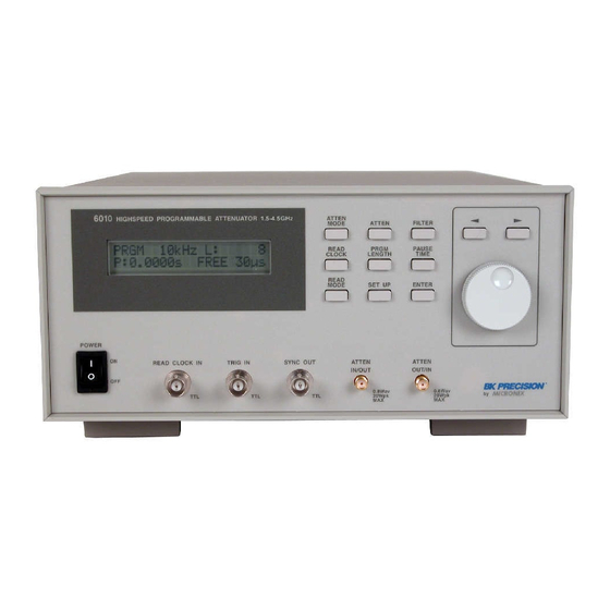
3. Description of panels 3.1 Front panel ①POWER - Main power switch. ②READ CLOCK IN - READ CLOCK input terminal. Apply an external clock signal with a maximum of 500 kHz to this input. ③TRIG IN - Apply a TTL level trigger signal to this terminal when in BURST or GATE mode. Readout of attenuation data is triggered by rising edge (BURST mode) or when signal is TTL high (GATE mode). - Page 10 ⑧READ CLOCK - Key for selection of program memory read clock frequency. ⑨READ MODE - Key for selecting BURST, GATE or FREE program execution mode. ⑩ATTEN - Key for setting attenuation values in manual mode. ⑪PROGM LENGTH - Key for setting the program memory length. ⑫SET UP - Key for interface configuration.
-
Page 11: 3.2 Rear Panel
3.2 Rear panel ①AC line input - Connector for supplying AC power to the instrument. Use the provided power cord to connect to a power outlet. The AC voltage range is 90 - 130V or 180 - 250V. Make sure that the supplied voltage is within this range. -
Page 12: 4.Operation
4. Operation 4.1 Manual and program mode - Select the attenuator control mode. The cursor on the screen moves to [MANUAL] or [PRGM] at positions indicated below when the <ATTN MODE> key is pressed. [MANUAL] mode screen MANUAL 23.45dB 10μs [PRGM] mode screen PRGM 500KHz L:131072... -
Page 13: Filter
4.3 FILTER - Set the attenuator switching response time. The cursor moves to the position indicated below when the <FILTER> key is pressed. This parameter can be set in either [MANUAL] mode or [PRGM] mode. [MANUAL] mode example: MANUAL 23.45dB 10μs [PRGM] mode example: PRGM 500KHz L:131072... -
Page 14: Pause Time
PRGM 500KHz L:131072 P:6.5535s FREE 10μs Move the cursor using cursor keys, and set a value in the range of 8 - 131072 using the rotary knob. It is provided, however, that the upper limit depends on the date length in the program memory. - Press the <... -
Page 15: Read Mode
② When [CLOCK] is selected the main screen is displayed and the cursor moves to the position indicated below. PRGM 500KHz L:131072 P:6.5535s FREE 10μs - Move the cursor using the cursor keys and set a value in the range of 0 - 65535 using the rotary knob. The cursor moves towards the most significant digit when <... -
Page 16: Set Up
① When [FREE] is selected, the program is read (i.e., run) and a delay of the pause time is created. This is repeated continuously. ② When [GATE] is selected, the program read and pause times are repeated while the signal input to terminal TRIG IN is TTL High or while the <ENTER>... -
Page 17: Set Menu Table
4.9 Setup menu table ATTEN MODE MANUAL ATTEN PRGM READ CLOCK PRGM LENGTH PAUSE TIME TIME CLOCK OFF READ MODE FILTER SET UP RS232C GPIB 4.10 List of abbreviations ATTEN‥ ‥ ‥ ‥ ‥ Attenuator PRGM‥ ‥ ‥ ‥ ‥ ‥ Program Trig‥ ‥ ‥ ‥ ‥ ‥ Trigger Sync‥... -
Page 18: 5.Attenuation Profile Creation Software
5. Software for creating attenuation profiles 5.1 Minimum system requirements - Windows PC with Windows 98/NT/2000/XP/Vista - CD-ROM drive - RS-232C port (for data transfer) 5.2 Installation and start-up ① Start SETUP.exe contained on the CD-ROM. The setup utility will start. For installation, follow the on-screen instructions. - Page 19 View Horizontal Zoom Zoom In Zoom Out Zoom Min Zoom Max Vertecal Zoom Zoom In Zoom Out Zoom Min Zoom Max X Scale Time Length Y Scale Ampl Full Scale Math Add Wave Form Add Wave Buffer Sub Wave Form Sub Wave Buffer Mul Wave Form Mul Wave Buffer Clipping Abs Mirror Horizontal Offset Vertical Smooth Resize Options Free Hand Line Select Select All Wave Form... Tool Bar Status Bar View Window...
-
Page 20: Operation
5.4 Operation (1) File - New Open a new edit screen. - Open Read the attenuation waveform data from a File and display it in the edit screen. The file format is binary. - Close Close the edit screen. - Save Save the attenuation waveform data to a binary file - Save As…... - Page 21 - Transmit… Transfer the attenuation data to the 6010/6011/6012/6013 - COM Port Configure your PC’s COM Port - Baud Rate Select the baud (transfer) rate. - Data Length Set the data size to be transferred (8 – 131072 words). - Filter Select the attenuator switching response time.
- Page 22 (2)Edit - Undo Cancel the previous action. - Cut Cut the selected data to the buffer. - Copy Copy the selected waveform data to the buffer. - Paste Paste the cut or copied data in the buffer to the selected position. - Delete Delete the selected data.
- Page 23 (3)View - Horizontal / Vertical Zoom Enlarge or reduce the horizontal axis, with the left end of the screen as the reference. Zoom In --- Enlarge Zoom Out --- Reduce. Zoom Max --- Maximum zoom Zoom Min --- Show complete time base (no zoom) Enlarge or reduce the vertical axis, with the center of the screen as the reference.
- Page 24 (4)Math - Add Wave Form Add a standard waveform, to the wave form in the editing window. - Add Wave Buffer Add the cut or copied data in the buffer to the specified waveform. - Sub Wave Form Subtract a standard waveform from the wave form in the editing window - Sub Wave Buffer Subtract the cut or copied data in the buffer from the specified waveform.
- Page 25 -Clipping Limit (clip) the waveform to the limit points (Y1, Y2) within the horizontal range defined by (X1, X2) ‚w‚P ‚w‚Q ‚w‚P ‚w‚Q ‚x‚P ‚x‚P ‚x‚Q ‚x‚Q The waveform before and after clipping To perform this operation: Select Clipping. Click on the waveform in the editing window, press and hold the left mouse key, define a horizontal line then release the mouse key.
- Page 26 - Mirror/Vertical On the graph f(x) between X1 and X2, reflect f(x) about a horizontal line ‚w‚P ‚w‚Q ‚w‚P ‚w‚Q The waveform is being reflected about a horizontal line (x-axis) To perform this operation: Select Mirror/Vertical. Click on the waveform in the editing window, press and hold the left mouse key, define a horizontal line then release mouse key - Offset Bring the range (X1, X2) between 2 specified points in the horizontal direction to the end point (Y1)
- Page 27 The data will be compressed according to the factor selected. Example: The maximum amplitude of a sine wave profile is 20dB. By selecting 50 for the Y size, all amplitude values will be decreased by 50% and the maximum amplitude will be 10 dB. The time axis will be adjusted accordingly (5) Option - Free Hand...
- Page 28 automatically connected to the existing waveform. Or: Modify an existing waveform by clicking on the waveform, then dragging it to a new area. - Select Select a portion of the wave that is the object of the edit or arithmetic operation. - Select All The entire waveform is selected.
- Page 29 Parameter Setting range Applicable waveform LENGTH [W] (number of data) 8 – 131072 All waveforms CYCLES (cycle) 1 – 100 All except DC AMPL [dB] (amplitude) 0 – 80 dB All waveforms OFFSET [dB] (offset) 0 – 80dB All except of DC PHASE [deg] (phase) 0 –...
- Page 30 - About The program’s version information is displayed. Test Equipment Depot - 800.517.8431 - 99 Washington Street Melrose, MA 02176 FAX 781.665.0780 - TestEquipmentDepot.com...
-
Page 31: 6.Remote Interface
The transmission of each standard command has to be preceded by a “CY” handshake. The computer program must send the ASCII character 'C' to the 6010 to which the 6010 attenuator responds by sending 'Y' followed by CRLF. Only after successful exchange of this handshake will a standard command be accepted by the attenuator. -
Page 32: Gpib Protocol
Each data word is transferred in the order of Low Byte first, High byte second. 80dB or 8640h would be transmitted as 4086h. (Note: h denotes hexadecimal value) Sequence for transmission of an arbitrary waveform data block: 6010 "C" ------>... -
Page 33: Command List
6.3 Command list Command Data part Explanation The control mode of the attenuator is set to MANUAL mode. The control mode of the attenuator is set to PROGRAM mode. 0.00 – 80.00 Set the attenuation level when in MANUAL mode. 1US, 3US, 10US, 30US, Change filter constant (units are in µs and ms). -
Page 34: Example Program
MSComm1.Output = "C" Call WaitRes(3) ‘ receive ‘Y’+ CRLF MSComm1.Output = "LEN" + CStr(dl) + CrLf Call WaitRes(4) ‘ receive ‘OK’+ CRLF Visual Basic Form associated with above program sample Back to BK Precision 6010 Product Info Page Visit us at www.TestEquipmentDepot.com...
Need help?
Do you have a question about the 6010 and is the answer not in the manual?
Questions and answers