Table of Contents
Advertisement
Quick Links
Advertisement
Table of Contents

Related Manuals for Owon PCT513-TY


Summary of Contents for Owon PCT513-TY
- Page 1 PCT513-TY Wi-Fi Touchscreen Thermostat Quick Start Guide...
-
Page 2: Safety Handling
Safety Handling WARNING: Failure to follow these safety notices could result in fire, electric shock, other injuries, or damage to the Thermostat and other property. Read all the safety notices below before using the Thermostat. • Avoid high humidity or extreme temperatures. • Avoid long exposure to direct sunlight or strong ultraviolet light. -
Page 3: Overview Of This Guide
Overview of this guide Part 1 Welcome Page 4 A brief introduction to the smart thermostat Part 2 In the box Page 4 Components in the box Part 3 Installation Guide Page 5-8 Removing your old thermostat Page 9-12 New device installation with a C-wire Page 13-21 New device installation without a C-wire (Optional) Page 22-24 Wiring diagrams Part 4... - Page 4 Welcome The Wi-Fi Touchscreen thermostat makes it easier and smarter to control your household temperature. With the help of zone sensors, you can balance hot or cold spots throughout the home to achieve best comfort. You can also schedule your thermostat working hours to match your plans. This guide will provide you with an overview of the product and will help you understand how to use it.
-
Page 5: Removing Your Old Thermostat
Installation Guide 3-1 Removing your old thermostat Step 1. Switch off your HVAC system Before you start, please switch off your HVAC system to protect you and avoid blowing a fuse. Wait a few minutes, then try to adjust the temperature in your old thermostat to double check if the system is off. -
Page 6: Step 3. Compatibility Check
Step 3. Compatibility Check If you find a thick wire with wire nuts on the backplate of the old thermostat, or if the voltage of your old system is 120v or higher, it will not be compatible with PCT513. If none of the above, then please proceed to the next step. - Page 7 Step 5. Label the Wires with Tags Label each wire on the wallplate with the tags (label 1) provided. Then carefully disconnect the wires. Y1 Y2 W1 W2 RC RH G Note: If there are any jumper wires between Rh, Rc, or R terminals, do not label them.
-
Page 8: Connect Wires
3-2 Connect wires Do you have a C wire connected to your old thermostat? YES → 3-2-1 NO → 3-2-2 RC RH G Y1 Y2 W1 W2 Terminal designation: Terminals What it means 24VAC primary for cooling 24VAC primary for heating 24VAC common 1st stage Primary heating relay / Aux heat 2nd stage Secondary heating relay / Aux heat... -
Page 9: Install The Thermostat
3-2-1 Install the thermostat with a C-wire Step 1. Remove the wallplate Unscrew the wallplate from the wall and gently pull it out to ensure the wires do not fall back into the hole. RC RH G Y1 Y2 W1 W2 Step 2. -
Page 10: Step 3. Connect The Wires
Step 3. Connect the wires Connect wires to the base: Connect the R or RC wire into the RC terminal Connect other wires to the corresponding terminals Take a picture of the wires when you are finished. You may need to refer it for the wirings in the setup wizard later. -
Page 11: Step 4. Dip Switch
Step 4. DIP Switch If you have connected both the RC-wire and the RH-wire to the wallplate, adjust the DIP switch on the back of the thermostat to 'Disconnect'. Otherwise, switch it to 'Connect'. DIP switch RC&RH Connect Disconnect Step 5. Attach the PCT513 to the base Gently press the PCT513 into the base until it clicks. -
Page 12: Step 6. Power On Your System
Step 6. Power on your system Congratulation! The installation is finished. Please power on your HVAC system. Breaker box Switch Once powered up, the thermostat's screen will light up and display the setup wizard. You can complete the following configuration according to section 4. - Page 13 3-2-2 Install the thermostat without a C-wire (Optional) Power module Power module requires your system to have the following wires: 4 wires: W/W1, Y/Y1, G, and R (or Rc or Rh) or 3 wires: Y/Y1, G, and R (or Rc or Rh) RC RH G Y1 Y2 W1 W2 If you do not have these wires, your system may not be...
- Page 14 Description: The C-wire is used to provide power to the thermostat. If your system does not have the "C" wire, you can use the power module to power your thermostat using the existing wires. There are two sides with connections. One side (4 terminals) is for thermostat connections, the other side, pre-wired (5 terminals), is for the control board connections.
- Page 15 Step 1. Find the HVAC terminals Find the control board of your HVAC system. Open your HVAC system's cover and take a picture of the wires connected to the terminals of your old thermostat. You may need to reference this photo later. HVAC Control Board Step 2.
- Page 16 Step 3. Disconnect the wires Disconnect the W/W1, G, Y/Y1, R wires from the control board. Control Board ↓ To thermostat Step 4. Connect the wiring module Reconnect these wires to the 4-terminal side of the power module. The wires and corresponding terminals are shown below. R →...
- Page 17 Step 5. Connect the wires Generally, the control board will have W, C, G, Y and R terminals. Connect the pre-wired side of the power module (5 terminals) to the corresponding terminals on the HVAC control board. HVAC Control Board To thermostat To HVAC control board Power module...
- Page 18 Step 7. Add new tags Add new tags to the following tags to simplify your wiring: R/RC/RH → RC G → C Y/Y1 → S Label 1. Y/Y1 Y/Y1 RH Y2 W/W1 W/W1 If you have a C wire, you will not need the label 2 below.
- Page 19 Step 9. Attach the base of PCT513 to the wall Bundle and insert the wires through the hole of wall plate and the base of PCT513, then attach the base to the wall with the screws. Base Wall plate Step 10. Connect the wires First, connect 3 wires as shown below:...
- Page 20 Step 11. DIP Switch Adjust the DIP switch on the back of the thermostat to the 'Connect' side. DIP switch RC&RH Connect Disconnect Step 12. Attach the PCT513 to the base Gently press the PCT513 into the base until it clicks.
- Page 21 Step 13. Power on your system Congratulation! The installation is finished. Please power on your HVAC system. Switch Breaker box Once powered up, the thermostat's screen will light up and display the setup wizard. You can complete the following configuration according to section 4.
-
Page 22: Wiring Diagrams
Wiring diagrams Below are the wiring diagrams for common HVAC equipment. Conventional heating and cooling system Y2 W1 W2 Air conditioner Furnace For dual heat and cooling system, if applicable. Remove the jumper between Rh, Rc, or R terminals, adjust the DIP switch on the back of the thermostat to 'Disconnect' if you have connected both RC-wire and RH-wire to the wallplate, otherwise switch it to the 'Connect' side. - Page 23 Heat pump (air or geothermal) with auxiliary heat W1 W2 O/B W1 W2 Y1 Y2 Air handler Heat pump For dual heat and cooling system, if applicable. Remove the jumper between Rh, Rc, or R terminals, adjust the DIP switch on the back of the thermostat to 'Disconnect' if you have connected both RC-wire and RH-wire to the wallplate, otherwise switch it to the 'Connect' side.
-
Page 24: Boiler Or Radiant System With Air Handler And Conventional Cooling Or Heat Pump
Boiler or radiant system with air handler and conventional cooling or heat pump Air handler Air conditioner or Heat pump Boiler For dual heat and cooling system, if applicable. For heat pump only. Remove the jumper between Rh, Rc, or R terminals, adjust the DIP switch on the back of the thermostat to 'Disconnect' if you have connected both RC-wire and RH-wire to the wallplate, otherwise switch it to the 'Connect' side. - Page 25 Congratulations, you have completed the wiring! To complete your setup, follow the instructions on the configuration guide below. In here you will find: — App and device user guide — Meet your thermostat — FAQ...
-
Page 26: Get Started
Get started Follow the wizard first to complete the thermostat setup based on your HVAC system. • Wiring Next 4.1 To get started, you will need: • Connect your phone to the Wi-Fi network. • A mobile phone with a 'SmartLife' APP installed. •... - Page 27 • Confirm that both the location permission of phone system and 'SmartLife' App are enabled. Phone system ← SmartLife ← ←...
- Page 28 4.2 Configuration: 1. Click the Wi-Fi icon on the home screen to configure Wi-Fi. 12:00 27.5 ? Cool to 26.o Follow Schedule The LED status gives the following information of the thermostat: LED status What it means Rapidly blink: EZ pair mode Red LED Slowly blink: AP pair mode Device has connected with router...
- Page 29 2. Select the network configuration mode. It may take a while to switch between the two modes. • EZ pair mode (Default): Quick pair devices. You can set all devices to this mode, and then add devices in batches on your phone. •...
- Page 30 7. Enter your home Wi-Fi account and password. If your router supports both 2.4Ghz and 5Ghz, please add device under 2.4G Wi-Fi channel. You can follow the following step on the App to configure the router. After that, tap "Next" button to continue to configure the Wi-Fi. 8.
-
Page 31: System Mode
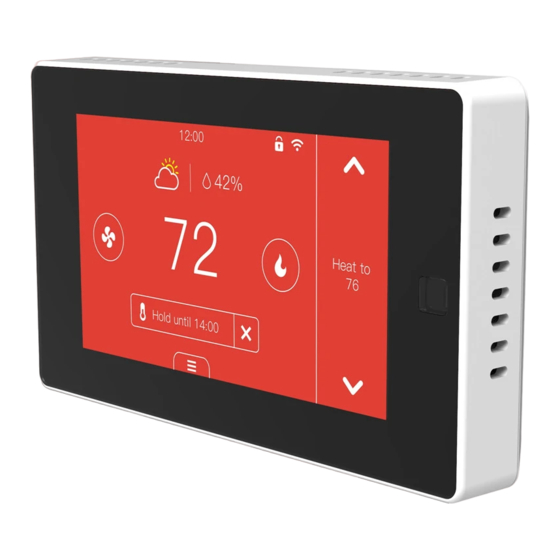
Meet Your Thermostat 5.1 Device Overview Main page Outdoor Temperature &Indoor Humidity Date&Time Locked Wi-Fi Indoor 12:00 Turn up temperature 27.5 27.5 Heat to 16.0 Target mode temperature Cool to Hold 29.0 Follow Schedule mode Turn down System Menu mode You can select the heating/cooling target temperature to adjust separately or press the up and down buttons to adjust it simultaneously. - Page 32 • Heat: Heating only • Cool: Cooling only • Auto: Automatic control of heating and cooling based on ambient temperature • Emergency Heat: In this mode the thermostat will only call backup system • Off: Turn the HVAC system off Fan mode •...
-
Page 33: Hold Mode
Hold mode There are three hold modes that you can select • Hold Temporary Permanent Follow Hold Hold Schedule • Temporary Hold: Keep the current target temperature until the next scheduled activity begins. • Permanent Hold: Always hold the current target temperature. It will override the current schedule settings. -
Page 34: Vacation Mode
12:00 27.5 27.5 Heat to 16.0 Cool to 29.0 Undo Hold until 14:00 Hold temperature until next schedule Vacation mode You can set the vacation mode in 'Menu'->'Vacation'. Set the time of departure and return, as well as the highest and lowest temperatures during this period. -
Page 35: Conventional: Cooling
Display Below are the meanings of various display changes and alerts: Heating or cooling state Red: Heating Blue: Cooling 12:00 12:00 22.5 27.5 27.5 27.5 Heat to Heat to 23.0 23.0 Cool to Cool to 26.0 26.0 Follow Schedule Follow Schedule Compressor protection 12:00 31.0... - Page 36 System or network alerts When the outdoor temperature is below the 'Compressor Min Outdoor Temp' you set, the icon on system mode will display and the compressor will be turned off automatically. When the outdoor temperature is higher than the 'AUX Heat Max Outdoor Temp' you set, the icon on system mode will display and the AUX Heat will be turned off automatically.
- Page 37 Menu • Memu System Vacation Sensors Schedule Settings Lock System • HVAC: Switch system mode (Heat/Cool/Auto/Emergency Heat/Off) • Fan: Switch fan mode (ON/Auto/Cir) Sensors Add multi sensors to balance the current temperature throughout the home. Schedule Set Schedule to change the temperature automatically. Vacation Set vacation to change the temperature automatically.
- Page 38 Settings • Date &Time: Set time format. You can also set the time manually when the device is not configured with a network. • Fan Run Time: Set minimum fan run time in 'Cir' mode • Wi-Fi: Configurate and display Wi-Fi information •...
- Page 39 Advanced (Different wiring configurations will display different): 1. Heat/Cool Dissipation Time When the heating/cooling stops, the fan shuts off with a delay. 2. Compressor Protect Time A time countdown to protect compressor when starting frequently. 3. Compressor Min Outdoor Temp When the outdoor temperature is below this temperature, the compressor will not be used.
-
Page 40: App Overview
Equipment Test: Test whether the corresponding function of the equipment can run normally as required • Filter: Filter change reminder • Reset: Reset setting Reset schedule (Reset system schedule and clear vacation) Reset all (reset the thermostat to default factory setting) •... - Page 41 Home: 1. Device list You can check the added device, tap one to enter control page. You can drop it down to refresh the list. 2. Location information Information about your local weather conditions 3. Home management Add or delete home and manage home names, rooms, locations, and members 4.
-
Page 42: Control Page
Control page Indoor Humidity Device management Fan is working Target temperature Indoor temperature System mode Fan mode Hold mode Setting • System mode: Displays the current system mode. Tap it to switch the mode. • Fan mode: Displays the current fan mode. Tap it to switch the mode. •... - Page 43 1.How to pair the thermostat with Remote Zone Sensors? 1. Click the '+' button at the top right of the interface in 'Menu' -> 'Sensors' on the thermostat and tap 'Next'. • Sensors Pair Please press and hold the button on the back of the sensor for 3 seconds, the indicator will flash red, then tap ‘Next’.
- Page 44 2. Wi-Fi configuration of the thermostat failed - Confirm the entered router password is correct. - Please confirm the network is stable. Put the phone besides your thermostat and make sure they are in the same network environment. Try opening a website to judge if the network can be used. - Confirm adding device is under 2.4G WI-FI channel.
- Page 45 4. Configure the network in AP mode 1. Click the Wi-Fi icon on the home screen to configure Wi-Fi. 12:00 27.5 ? Cool to 26.o Follow Schedule 2. Select the AP mode. It may take a while to switch between the two modes. 3.
- Page 46 ← 7. Enter your home Wi-Fi account and password (Only support 2.4Ghz Wi- Fi), then tap "Next" button.
- Page 47 8. Switch the network configuration mode to AP mode at the upper right corner of the APP. ← 9. Place the router, mobile phone and thermostat as close as possible. Confirm the indicator on your device is slowly blink, then tap "Next" to wait for connection.
- Page 48 10. Find and connect the device's hotspot in the Wi-Fi list. 11. After the connection succeeds, you can rename the thermostat and click "Done" to complete the configuration. (If failed, please refer to FAQ2 to troubleshoot)
- Page 49 5.Enable voice control ← Tap ''Device management'' at the top right of the control page, then link your Alexa/Google account. Voice Support: 1. Ask about the current temperature in Heat/Cool/Auto mode. "Alexa/OK Google, what's the temperature of [thermostat name]" "Alexa/OK Google, what's the [thermostat name] temperature?" "Alexa/OK Google, ask [thermostat name] the temperature"...
- Page 50 "Alexa/OK Google, raise/lower the thermostat temperature by [number]" "Alexa/OK Google, raise/lower the [thermostat name] temperature by [number]" "Alexa/OK Google, increase/decrease the [thermostat name] temperature" "Alexa/OK Google, increase/decrease [thermostat name] by [number]" "Alexa/OK Google, make it cooler in [thermostat name]" "Alexa/OK Google, make it warmer in [thermostat name]" Note: If you change the temperature by voice on auto mode.
-
Page 51: Technical Specifications
Technical specifications Thermostat: Compatibility • Conventional: 2-stage heating and 2-stage cooling HVAC systems • Heat Pump: 2-stage heating, 2-stage cooling, 2-aux heating Compatible systems • Supports natural gas, electric, hot water, steam or gravity, gas fireplaces (24 Volts), oil heat sources •... - Page 52 Electrical Rating • 24 VAC, 1A Carry; 5A Surge 50/60 Hz • 0~ 50° C, 32 ~122° F Operating Environment • Humidity range: 5%~95% Storage Temperature • -30 ~ 60° C , -22° F ~ 140° F • 18 AWG, Requires both R and C wires Wiring from the HVAC System Dimensions...
Need help?
Do you have a question about the PCT513-TY and is the answer not in the manual?
Questions and answers