
Summary of Contents for LOFTNESS Battle Ax 30 Series
- Page 1 Battle Ax Excavator Mulching Head - 30 Series 41 • 51 Owner’s Manual and Parts Book (Originating w/Serial Number 101-136) Model Number: Serial Number: Date of Purchase: 208186 Rev. C 08.02.22...
- Page 3 All Loftness products have a one (1) year limited warranty. The XLB10 Grain Bag Loader has a two (2) year limited warranty. If any Loftness product is used as rental or leased equipment the limited warranty period is for only 30 days from the delivery date to the original customers.
- Page 5 ____ Assisted customer with completing / submitting Warranty Registration Form to Loftness by one of the below options. Dealer also needs to submit a copy of this completed PDI to Loftness and maintain the copy in owner’s manual for unit.
- Page 7 ____ Assisted customer with completing / submitting Warranty Registration Form to Loftness by one of the below options. Dealer also needs to submit a copy of this completed PDI to Loftness and maintain the copy in owner’s manual for unit.
-
Page 9: Table Of Contents
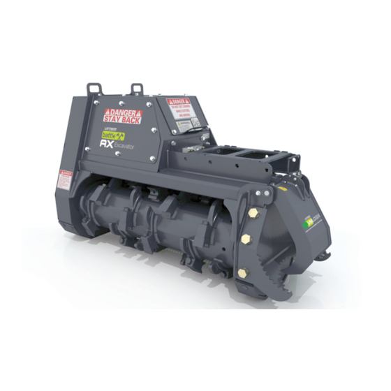
Battle Ax 30 Series (Example) ........ - Page 10 Battle Ax 30 Series, Complete ........
-
Page 11: Ordering Code
The ordering code will consist of two numbers (machine size), two letters and two numbers (machine type), one letter (cutter type), two numbers (motor system), one letter (sheave/belt combo), and one or two letters (options). An example for a Battle Ax 30 series of this type would be as shown below. 51BX30Q57A.H SIZE 41 = 41"... - Page 12 Battle Ax OM...
-
Page 13: Introduction
The Loftness Battle Ax is an effective, reliable machine used for maintaining grass, weeds, brush and trees. For best results, operate the machine as low to the ground as possible without the teeth striking ground or other obstructions. -
Page 14: Battle Ax Features
Introduction Battle Ax Features • Hydraulic Driven. • 37 mm Synchronous Belt. • Built-in Depth Gauges - controls cutting depth. • Two-stage Cutting Chamber - uses 2 shear bars, producing a finer mulch with less passes. • Double Carbide, Planer (sharpenable), or Planer Hard Surfaced Teeth (sharpenable). -
Page 15: Safety Instructions
Safety First Be certain all machine operators are aware of the dangers indicated by safety decals applied to the machine, and be certain they follow all safety decal Safety Alert Symbol instructions. Contact Loftness for safety decal replacement. This message alert... -
Page 16: Mandatory Shut-Down Procedure
Safety Instructions Mandatory Shut-Down Procedure • Always have an operator in the machine while the attachment is in operation. Never leave the machine and attachment running and unattended. • Stop the machine and attachment on a level surface and lower the attachment to the ground. •... -
Page 17: Hydraulic Safety
Safety Instructions Safety Rules (Cont’d) • Know the area before operating the machine. Be aware of power lines or other equipment. • Make sure the operator’s area is clear of any • Do not lubricate parts while the machine is running. distracting objects. -
Page 18: Safety Decal Locations
Safety Instructions Safety Decal Locations Check and replace any worn, torn, hard to read or missing safety decals on your machine. NOTE: This section shows where safety-related decals are applied on the machine. For all machine decals see “Machine Decals and Signs” on page 44. See the following page for detailed images of the safety decals called out above. - Page 19 Safety Instructions Safety Decal Locations (Cont’d) Part No. 4334 Part No. N17013 Part No. N28386 Part No. 203264 Part No. 208824 WARNING SKIN PUNCTURE HAZARD. HYDRAULIC LINES. Protect hands and body from high pressure fluids. N23506 Part No. 200491 Part No. N23506 Part No.
-
Page 20: Battle Ax Identification
Safety Instructions Battle Ax Identification Front Motor Cover Drive Sheave Drive Belt Rotor Sheave Skid Rotor Cutting Teeth Drive Belt Skid Cover Top Motor Cover Hydraulic Hose Connections Mounting Plate Hydraulic Motor Hydraulic Thumb Compartment (optional) Shipping Stand Manual QR Code Deflector Chains Hook... -
Page 21: Set-Up Instructions
Do not cap Case Case Drain For a mounting bracket specific to your model of Drain Protection. -12FJIC excavator, contact Loftness. NOTE: Make sure hydraulic hoses are connected to the Battle Ax before installing the mounting bracket. Tank -16 Code 62 Split Flange... -
Page 22: Remove Shipping Stands
Set-up Instructions Remove Shipping Stands Checking Rotor Rotation DANGER: Keep hands, feet, and clothing clear of rotor and bearings while excavator is running. Stands (1) are secured to the Battle Ax to keep it stable during shipping. These can be removed after the unit is initially mounted to the excavator. -
Page 23: Checking Rotor Speed
Set-up Instructions Checking Rotor Speed Adjusting Rotor RPM NOTE: Motor is preset at the factory to maximum DANGER: Shut down power from the displacement. Motor displacement must be excavator before removing the bearing cover adjusted on the cutter head to achieve the and applying reflective tape to rotor shaft end. - Page 24 Set-up Instructions Adjusting Rotor RPM (Cont’d) NOTE: Hydraulic hoses hidden for clarity. NOTE: Motor adjustments need to be done with auxiliary hydraulics disengaged. To INCREASE ROTOR RPM: Loosen jam nuts (1 and 2) using a 19 mm offset box end wrench while holding the adjustment screw stationary with a 6mm Allen wrench.
-
Page 25: Operating Instructions
RPM. Check with your When mulching large trees, work from the top down. Loftness dealer to be sure your attachment is In wet conditions, operate at a slower speed and set-up with the correct hydraulic motor to... -
Page 26: Detaching Battle Ax
Operating Instructions Detaching Battle Ax Park excavator on a dry level surface. Turn power off to the Battle Ax and install shipping stands. See “Remove Shipping Stands” on page 12 for reference. Lower the Battle Ax to the ground. Shut off engine and remove key. Disconnect hydraulic hoses. -
Page 27: Maintenance
Maintenance General Maintenance Lubrication To ensure efficient operation, you should inspect, Grease Points Location lubricate, and make necessary adjustments and repairs at regular intervals. Parts that are starting to show Use a #2 general purpose lithium based grease unless wear should be ordered ahead of time, before a costly noted otherwise. -
Page 28: Overhung Load Adapter
Maintenance Lubrication (Cont’d) Reinsert the plug back into the top port and tighten. NOTE: If replacing bearings or seals in the overhung Grease Points Location (Cont’d) load adapter, be certain to refill with hydraulic fluid after reassembly. Removing Belt Cover DANGER: Shut down and lock out power from the excavator before removing the belt covers. -
Page 29: Removing Motor Covers
Maintenance Removing Motor Covers Removing Hook DANGER: Shut down and lock out power DANGER: Shut down and lock out power from the excavator before removing any or all from the excavator before removing the hook. of the motor covers. Failure to do so could Failure to do so could result in serious injury result in serious injury or death. -
Page 30: Tooth Removal And Installation
Maintenance Tooth Removal and Installation DANGER: Shut down and lock out power from the excavator before removing and installing any cutting teeth. Failure to do so could result in serious injury or death. NOTE: The cutter teeth have been heat treated to a specific hardness. -
Page 31: Belt Tension Adjustment
Maintenance Belt Tension Adjustment NOTE: When replacing or installing a new belt, align the grooves in the belt with the upper and lower pulleys. WARNING: Shut down and lock out power from the excavator before adjusting the drive Install the belt and adjust the tension accordingly. Refer belt. -
Page 32: Skid Removal/Replacement
Maintenance Sprocket Removal (Cont’d) Skid Removal/Replacement Tighten the screw until bushing grip is released. (If WARNING: Shut down and lock out power excessively tight, lightly hammer face of sprocket from the excavator before removing skids. using drift pin or sleeve). Lift the Battle Ax off of the ground about 6 inches. -
Page 33: Cutter Bar Adjustment
Maintenance Cutter Bar Adjustment Storage End of Season • Clean entire Battle Ax thoroughly. • Lubricate all parts of the machine. See “Lubrication” on page 17. • Make a list of all worn or damaged parts and replace them. • Paint all parts that are worn or rusted. -
Page 34: Troubleshooting
Maintenance Troubleshooting PROBLEM CAUSE SOLUTION Excessive vibration. Broken or missing teeth. Replace teeth. Mud and/or debris wrapped around Clean the Battle Ax. the rotor. Faulty rotor bearing. Replace bearing(s). Damage to rotor (includes bent end Consult factory. of shafts, missing balance weights, or actual rotor deformity from striking rocks, etc.) Uneven cutting. -
Page 35: Parts Identification
Parts Identification PARTS IDENTIFICATION Battle Ax OM... -
Page 36: Battle Ax 30 Series, Complete
Parts Identification Battle Ax 30 Series, Complete 7 (Option) (Option) Detailed parts breakdowns of the assemblies above (items) are listed on the following pages: Item 1 - Belt Assembly (208066) - See page 36. Item 2 - Motor Assembly, 6000PSI (208223)- See page 38. - Page 37 Parts Identification Battle Ax 30 Series, Complete QTY. PART # DESCRIPTION 208066 BELT ASSY, 50 TOP 50 BOTTOM 37MM 208223 MOTOR ASM, LINDE 105CC 132GPM/6000PSI HMR 57 208054 ROTOR, ASSY PLANER - 41" 208069 51" 208310 ROTOR, ASSY HARD SURFACE PLANER - 41"...
-
Page 38: Covers, Skid Shoes, Hook, And Hitch Mount
Parts Identification Covers, Skid Shoes, Hook, and Hitch Mount (Option) Battle Ax OM... - Page 39 Parts Identification Covers, Skid Shoes, Hook, and Hitch Mount QTY. PART # DESCRIPTION N26748 BOLT, 1/2" X 1" SER FLG 208042 COVER, TOP MOTOR W/ DECALS 208033 COVER, BELT W/STIFFENER 208114 COVER, MOTOR 208047 SKID, WITH BRACE 4055 NUT, LOCK 5/8" TOP 4386 BOLT, CARRIAGE 5/8"...
-
Page 40: Cutter Bar, Deflector Chains, Motor Tension Hardware, And Manual Holder
Parts Identification Cutter Bar, Deflector Chains, Motor Tension Hardware, and Manual Holder Battle Ax OM... - Page 41 Parts Identification Cutter Bar, Deflector Chains, Motor Tension Hardware, and Manual Holder QTY. PART # DESCRIPTION 4014 BOLT, 1/2" X 1-3/4" GRADE 5 202962 STAND, SHIPPING W/ DECAL 4068 WASHER, 1/2" SAE FLAT 4054 NUT, LOCK 1/2" TOP 4375 PIN, ROLL 3/16" X 1" 202879 CHAIN, 5/16 DEFLECTOR 9 LINK - 41"...
-
Page 42: Rotor Assembly, 41" Battle Ax With Planer
Parts Identification Rotor Assembly, 41" Battle Ax with Planer (208054) Rotor Assembly, 41" Battle Ax with Hard Surface Planer (208310) Rotor Assembly, 41" Battle Ax with Double Carbide (208322) 11a, 11b, 11c Battle Ax OM... - Page 43 Parts Identification Rotor Assembly, 41" Battle Ax with Planer (208054) Rotor Assembly, 41" Battle Ax with Hard Surface Planer (208310) Rotor Assembly, 41" Battle Ax with Double Carbide (208322) QTY. PART # DESCRIPTION N20043 BOLT, 1/2" X 2-1/4" FN TD GR 8 N16472 WASHER, 1/2 NORDLOCK N16417...
-
Page 44: Rotor Assembly, 51" Battle Ax With Double Carbide (208339)
Parts Identification Rotor Assembly, 51" Battle Ax with Planer (208069) Rotor Assembly, 51" Battle Ax with Hard Surface Planer (208337) Rotor Assembly, 51" Battle Ax with Double Carbide (208339) 11a, 11b, 11c Battle Ax OM... - Page 45 Parts Identification Rotor Assembly, 51" Battle Ax with Planer (208069) Rotor Assembly, 51" Battle Ax with Hard Surface Planer (208337) Rotor Assembly, 51" Battle Ax with Double Carbide (208339) QTY. PART # DESCRIPTION N20043 BOLT, 1/2" X 2-1/4" FN TD GR 8 N16472 WASHER, 1/2 NORDLOCK N16417...
-
Page 46: Belt Assembly, 50T 50B 37Mm 1750 (208066)
Parts Identification Belt Assembly, 50T 50B 37MM 1750 (208066) QTY. PART # DESCRIPTION 200286 SPROCKET, 14MM 50 TOOTH X 37 N20805 BUSHING, 1-1/2" TPL 3020 7121-03 KEY, 3/8" X 2" 208068 BELT, POLY CHAIN 14MM 1750 X 37 N18975 BUSHING, 2 3/16 TPL 3020 7122-04 KEY, 1/2"... -
Page 47: Lubrication
Parts Identification Lubrication QTY. PART # DESCRIPTION N17007 GREASEZERK, 1/8" NPT 4304-10 BULKHEAD, FITTING-GREASE HOSE 4304 HOSE, GREASE 1/8" x 15" W/FITTINGS 4472 ELBOW, 1/8" 90 DEG.STREET Battle Ax OM... -
Page 48: Motor Assembly, Linde 105Cc - #57 Motor System (208223)
Parts Identification Motor Assembly, Linde 105cc - #57 Motor System (208223) 13 (Tank) † 14 (Pressure) 16 (Tank) (Case Drain) (Pressure) * For parts breakdown of item 6, Overhung Load Adapter (N20901), see page 40. ** For parts breakdown of item 7, Motor (N49001), see page 41. †... - Page 49 Parts Identification Motor Assembly, Linde 105cc - #57 Motor System (208223) QTY. PART # DESCRIPTION 4466 BOLT, 1/2" X 1-1/2" GRADE 8 N16472 WASHER, 1/2 NORDLOCK N16509 BOLT, 3/4" X 2" FN THD GR 8 N28567 WASHER, 3/4 NORDLOCK SP 202935 MOUNT, MOTOR N20901...
-
Page 50: Overhung Load Adapter (N20901)
Parts Identification Overhung Load Adapter (N20901) QTY. PART # DESCRIPTION N28566 REBUILD KIT (Includes Items 1, 2, 3, 4, and 6.) N28447 SEAL, FRONT N34130 CUP BEARING N34131 CONE BEARING N28448 SEAL, REAR N34132 RETAINING RING N14159 GASKET Battle Ax OM... -
Page 51: Motor, 105Cc Adjustable, Linde (N49001)
Parts Identification Motor, 105cc Adjustable, Linde (N49001) QTY. PART # DESCRIPTION 206841 KIT, SEAL LINDE MOTOR (Includes items 1, 2 and 3) – SHIM 56X72X1 205045 SEAL, SHAFT LINDE – O-RINGS Battle Ax OM... -
Page 52: Manifold, Check 132Gpm 6000Psi (208237)
Parts Identification Manifold, Check 132GPM 6000PSI (208237) Tank Tank Pressure Pressure QTY. PART # DESCRIPTION N28281 PLUG, 10MOR HOLLOW HEX 208239 CARTRIDGE, CHECK Battle Ax OM... -
Page 53: Thumb (208105) - (Optional)
Parts Identification Thumb (208105) - (Optional) QTY. PART # DESCRIPTION N26743 BOLT, 3/8" X 1" SER FLG 4052 NUT, LOCK 3/8" 208111 PIN, THUMB 208106 WELDMENT, THUMB N28010 DECAL, GREASE GUN 8 N28577 DECAL, VMLOGIX SMALL 207887 PIN, THUMB 207740 CYLINDER, 1"X 4"... -
Page 54: Machine Decals And Signs
Parts Identification Machine Decals and Signs Part No. N28386 NOTE: All safety related decals are also shown in the Safety Instructions Section along with their location on the machine. See “Safety Decal Locations” on page 8. Check and replace any worn, torn, hard to read or missing decals on your machine. - Page 55 Parts Identification Machine Decals and Signs (Cont’d) Part No. 203264 Part No. N13721 Part No. 207851 Part No. N49281 - (Small) CASE DRAIN PROTECTION DO NOT CAP 207851 Part No. N28010 Part No. N33105 Part No. N28576 - (Large) Part No. 209499 Part No.
- Page 56 Battle Ax OM...
-
Page 57: Appendix
Appendix Specifications BATTLE AX 30 SERIES DESCRIPTION 41" 51" Cutting Width 41 in. (104.14 cm) 51 in. (129.5 cm) Motor Adjustable Displacement Piston Motor 105cc Rotor Bearing 2-3/16 in. Piloted Double Taper Rotor Tip Diameter 17 in. (43.1 cm) Sprockets... -
Page 58: Dimensions
Appendix Dimensions BATTLE AX 30 SERIES DESCRIPTION 41" 51" Cutting Path (A) 41 in. (104.1 cm) 51 in. (129.5 cm) Overall Length (B) 63.8 in. (162.0 cm) 73.8 in. (187.5 cm) Overall Width (C) 27.7 in. (70.4 cm) 27.7 in. (70.4 cm) Overall Height (D) 38.3 in. -
Page 59: Torque Specifications
Appendix Torque Specifications Inches Hardware and Lock Nuts Battle Ax OM... -
Page 60: Metric Hardware And Lock Nuts
Appendix Torque Specifications (Cont’d) Metric Hardware and Lock Nuts Battle Ax OM... - Page 62 Loftness Specialized Equipment, Inc. 650 So. Main Street • PO Box 337 • Hector, MN 55342 Tel: 320.848.6266 • Fax: 320.848.6269 • Toll Free: 1.800.828.7624 Printed in USA © Loftness 2022...
Need help?
Do you have a question about the Battle Ax 30 Series and is the answer not in the manual?
Questions and answers