Table of Contents
Advertisement
Quick Links
12 Channel Rack Mount
12 Channel Wall Mount
12 Channel Wall Mount
Hardwired
GenVI
Advanced Dimming and Power
Switching System
User Manual
LSC Control Systems ©
+61 3 9702 8000
info@lsccontrol.com.au
www.lsccontrol.com.au
6 Channel Rack Mount
6 Channel Wall Mount
6 Channel Wall Mount
Hardwired
August 2022
V4.02
Advertisement
Table of Contents
Troubleshooting

Subscribe to Our Youtube Channel
Related Manuals for LSC GenVI Series


Summary of Contents for LSC GenVI Series
- Page 1 12 Channel Wall Mount 6 Channel Wall Mount 12 Channel Wall Mount 6 Channel Wall Mount Hardwired Hardwired GenVI Advanced Dimming and Power Switching System User Manual LSC Control Systems © +61 3 9702 8000 info@lsccontrol.com.au V4.02 www.lsccontrol.com.au August 2022...
- Page 2 Information contained in this manual is subject to change without notice. In any event, LSC Control Systems Pty Ltd cannot be held liable for any direct, indirect, special, incidental, or consequential damages or loss whatsoever (including, without limitation, damages...
-
Page 3: Table Of Contents
Gen VI Dimmer User Manual Contents Introduction ....................6 About this Manual ....................... 6 1.1.1 Conventions Used in this Manual ................ 6 Overview ........................6 1.2.1 Features ......................6 1.2.2 GEN·VI Control Philosophy ................. 7 Quick Start Guide ..................8 DMX Address ......................8 Channel Modes ...................... - Page 4 Gen VI Dimmer User Manual Dimmer Status ......................19 Riggers Control......................20 5.5.1 Chaser ....................... 20 Config Menu ......................21 Dimmer or Trupower (Switch) ................... 21 DMX Menu ....................... 22 5.8.1 Patch ......................... 23 5.8.2 16 Bit DMX Control .................... 24 5.8.3 DMX Loss Memory ....................
- Page 5 Gen VI Dimmer User Manual 10.1 Overview ........................42 10.2 What is PTFD? ......................42 10.3 Opto-isolated Problems .................... 42 10.4 Hard Firing ........................ 42 10.5 The Proof........................43 Specifications and Output Options ............44 11.1 Rackmount GEN·VI ....................44 11.2 Wallmount Gen VI ....................
-
Page 6: Introduction
Individual dimmer channel settings for: o DMX address patching. o Minimum and maximum output levels. o Choice of three fade curves (linear, s, or custom) or LSC TruPower (switched) power output. • LSC TruPower (switched power) provides direct power output by utilising relays guaranteeing there are absolutely no electronics in the circuit to interfere with connected loads. -
Page 7: Gen·vi Control Philosophy
Gen VI Dimmer User Manual 1.2.2 GEN·VI Control Philosophy Each channel can be independently set to dim mode (with a selection of standard dimming curves in either 8-bit or 16-bit accuracy) or relay mode (TruPower) for direct power switching. The control source for each channel can be either, DMX Only. -
Page 8: Quick Start Guide
Gen VI Dimmer User Manual Quick Start Guide 2.1 DMX Address To patch all of the channels in one GEN·VI rack to sequential DMX slots use the View Mode button to select the “DMX Address” home page. Address DMX slot of first channel View DMX slot of... -
Page 9: Auto Power
Gen VI Dimmer User Manual Press a channel number to toggle its mode between “Dimmer” mode and “TruPower” (switch) mode. A light grey button indicates dimmer mode and a dark grey button indicates TruPower mode as shown in the “Legend”. Configure your channels then press Save. -
Page 10: Models
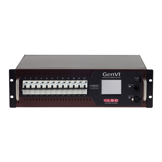
Gen VI Dimmer User Manual Models The GEN·VI rackmount is available in the following models, • 12 channels at 10 amps per channel. • 12 channels at 16 amps per channel. Not available for sale in Australia or New Zealand. •... -
Page 11: 100-120Vac Input Power
Gen VI Dimmer User Manual RCBO Output Breakers SD Card slot DMX Input DMX Thru 6 Channel GEN·VI Wallmount with internal output terminals 3.2 100-120VAC Input Power GEN·VI can be supplied from the factory for 100-120VAC input power operation. 3.3 Output Connectors Various output connector options are available. -
Page 12: Installation
All electrical work must be carried out by suitably qualified persons. 4.2 Unpacking The GEN·VI dimmer is fully tested and inspected before leaving the factory. Upon delivery, inspect the dimmer for signs of damage or mishandling. In the event of any damage, contact your LSC agent. 4.3 Installation 4.3.1 Rackmount GEN·VI... - Page 13 The front section can now be removed from the rear section by sliding it sideways off the split hinges. The rear section has provisions for mounting to walls and other upright structures such as uni-strut. Mounting brackets for P1000 Uni-Strut are available from LSC. Uni-Strut brackets Page 13...
-
Page 14: Patch Bay Installation
Gen VI Dimmer User Manual Min 155 mm Min 150 mm Min 150 mm Min 155 mm GEN-VI Wall Mount Rear Section Allow a minimum of 150mm clearance on either side of the dimmer to provide adequate ventilation and 155mm vertical clearance to allow units above and below to be opened. The dimmer weighs 21.5Kg. -
Page 15: Connections
If the DMX line ends at this dimmer (is not looped to other dimmers or devices) then the DMX TERM switch must be set to TERM using the touch screen. See section 5.9 LSC recommends the use of RS485 data cable or shielded CAT5 cable for the DMX connections. Audio or Microphone cables must not be used. -
Page 16: Configuration And Operation
Gen VI Dimmer User Manual Configuration and Operation 5.1 Overview The GEN·VI dimmer uses a touch screen with menus on the screen that provide the functions to configure and operate the dimmer. 5.2 Help Screens Several menus have Help screens available. Press the button (when available) to see the help screen. -
Page 17: Dmx Address
Gen VI Dimmer User Manual 5.3.2 DMX Address Patches are often performed in contiguous blocks of addresses. The “DMX Address” button provides a rapid method of patching all of the channels in one GEN·VI rack to sequential DMX slots, starting from a DMX address that you enter. -
Page 18: Status
To set a custom logo a special file must be present on an SD card inserted in the APS. There is a fee for LSC to convert your logo into the special file that will load into your APS. Please contact LSC or your LSC agent for details. -
Page 19: Dimmer Status
Gen VI Dimmer User Manual 5.4 Dimmer Status The large button at the bottom of both home pages shows the status of the following… Fan is running Temperature • Auto Power shows the status of channels set to “Auto Power”. These channels will be switched on whenever DMX is present. -
Page 20: Riggers Control
Gen VI Dimmer User Manual Touch anywhere within the legend window to close. 5.5 Riggers Control To set the level of a channel(s) (or run a chaser) from the touch screen, from either home page (above) press Riggers Control. Level Up & Output levels. -
Page 21: Config Menu
Each channel can be individually configured to be either a dimmed channel or a Trupower (switched) channel. Switched channels use LSC’s “TruPower” technology that provides direct power by utilising relays, guaranteeing there are absolutely no electronics in the circuit to interfere with connected loads. -
Page 22: Dmx Menu
Gen VI Dimmer User Manual “TruPower” is used for devices that do not fade, but need to be switched OFF or ON such as motors, discharge lamps and some LED fixtures. • When the control signal exceeds 60% the Trupower channel will switch ON. •... -
Page 23: Patch
Gen VI Dimmer User Manual 5.8.1 Patch Each GEN·VI dimmer unit numbers its channels from channel 1 through to channel 12. The patch menu allows you to patch (connect) DMX slots (addresses) from your DMX lighting controller to GEN·VI channel numbers. Patches are often performed in contiguous blocks of addresses. -
Page 24: Bit Dmx Control
Gen VI Dimmer User Manual If more than one channel is selected, then the lowest channel number will be patched to the selected DMX slot and the following dimmers will be patched to the sequential DMX slot numbers. For example, if channels 1, 2, 3 and 10 are selected and DMX slot number 24 is applied the result will be: Channel DMX Slot To patch multiple channels to the same DMX slot patch them one at a time. - Page 25 Gen VI Dimmer User Manual To create or edit a “DMX Loss Memory” press Config, DMX. The “DMX Loss Memory” pane has 3 buttons, • Press to create or edit the memory as described below • Press Delay to set the time that the GenVI will wait after DMX is lost, until its output fades to the “DMX Loss Memory”...
- Page 26 Gen VI Dimmer User Manual 5.8.3.1 Manually Setting Loss Memory Channel Levels The “DMX Loss Memory” menu (above) shows the first 6 channels. Use the < or > buttons to see the other groups of 6 channels. The navigator at the top right of the screen shows current group of 6 selected channels highlighted.
-
Page 27: Auto Power Enable And Hold Time
Gen VI Dimmer User Manual Fade Enter a time in seconds (0.02 to 99.99) then press Apply. 5.8.3.4 Fade In/Out The DMX Loss memory is normally activated automatically when DMX is lost but you can also manually fade the memory in or out using the Fade In / Fade Out button. Fade In/ Fade Out 5.8.4... -
Page 28: Auto Power Mode
Gen VI Dimmer User Manual Auto Power The “Auto Power” pane has 2 buttons, • Press Disable to disable the Auto Power function. The button then changes to Enable. This is a global setting for all channels that have their control source set to “Auto Power”. See below for details on how to set a channel to “Auto Power”... -
Page 29: View Input
Gen VI Dimmer User Manual Parameter Selector “Source” Parameter Parameter Selector Once “Source” is selected, the choose Auto Power then select Apply. 5.8.6 View Input The “DMX Setup” menu allows you to view the channel levels on the DMX input. To view the DMX input press Config, DMX, View Input. - Page 30 Gen VI Dimmer User Manual Each channel button shows the settings for that channel. For example: DMX Address Channel Output Number Max = 90% Control Source Min = 10% Curve = TruPower Control Source Curve = S Dimmer Channel 3 patched to DMX 55 Curve = Linear Curve = Custom...
-
Page 31: Min Level
90% will extend the life of a lamp as it never operates on full voltage or setting it to 50% provides 115 volt output. Note: The actual output voltage is dependent upon the dimmer curve. LSC recommends that you measure the output voltage (with a 240 volt load connected) to determine the “Max” level setting you require for a specific maximum voltage. - Page 32 GEN·VI dimmer. It is suitable for dimming LEDs. You can export the LSC custom curve and modify it to your own requirements. To do so, insert a SD card into the slot then select: Config, System, Import/Export, Export Curve. Transfer the “CURVE.DAT”...
-
Page 33: Source (Dmx Or Auto Power)
Gen VI Dimmer User Manual 5.10.4 Source (DMX or Auto Power) Select Config, Channels, select the channel number(s) then Edit then use the “Parameter Selector” buttons to select the “Source” parameter. Parameter Selector Parameter Selector The control source for each GEN·VI channel can be either, •... -
Page 34: Code (Software) Upgrade
5.12.1 Code (Software) Upgrade LSC Control Systems has a corporate policy of continuous improvement to its products. The GEN·VI dimmer software (firmware) is subject to this policy as new features are added and existing features improved. The software version of your GEN·VI dimmer can be checked from the “Dimmer Output”... -
Page 35: Import Export
Gen VI Dimmer User Manual There are two choices of fan control, • Auto Speed. The fan runs automatically when required. The higher the temperature the faster the fan runs • Constant Speed. The fan runs constantly at a speed that you set from the touch screen. The speed range is from 0 to 100%. - Page 36 Gen VI Dimmer User Manual Pressing a Lock button reveals a “Lock” keypad. Enter a four digit code and the Lock button appears. Press Lock to lock the selected level. If “User” or “Config” are locked, the “Config” button is replaced by a Padlock symbol. Locked To unlock, press the symbol and enter your 4 digit code.
-
Page 37: Alarms And Troubleshooting
Gen VI Dimmer User Manual Alarms and Troubleshooting Warning. No user controls or user serviceable parts are located inside the GEN·VI Dimmer. Refer all servicing to suitably qualified personnel. 6.1 Maintenance Ensure that the air vents are free from dust. Check that the GEN·VI contains the latest software release. -
Page 38: Trouble Shooting
Gen VI Dimmer User Manual Either reduce the load or increase the cooling to reduce the temperature. If the fan has been set to a constant slow speed, either increase the speed or set it to “Automatic”. See section 5.12.3. Also check that the fan is operating and that the sides of the dimmer are not blocked. -
Page 39: Houston X
Gen VI Dimmer User Manual HOUSTON X HOUSTON X is LSC’s monitoring and remote configuration tool that works with LSC products such as APS, GEN VI, MDR-DIN, LED-CV4, UNITOUR, UNITY and Mantra Mini. HOUSTON X can be downloaded from the LSC website, www.lsccontrol.com.au... -
Page 40: Dmx Explained
Gen VI Dimmer User Manual DMX Explained 8.1 Overview DMX512/1990-A is the industry standard for the transmission of digital control signals between lighting equipment. It utilises just a single pair of wires on which is transmitted the level information for the control of up to 512 DMX slots (addresses or channels). The information for each slot is sent sequentially. -
Page 41: Rdm
9.2 GEN·VI RDM LSC’s GEN·VI Dimmer range are RDM enabled products. This allows you to use RDM to change the DMX address of the dimmer and to interrogate the dimmer to find out its. -
Page 42: Ptfd Explained
PTFD stands for “Pulse Transformer Fired Dimmer”. It is a tried and proven piece of dimmer technology that is used in top quality dimmers including LSC’s GEN·VI range. However, many dimmer manufacturers now use low cost opto-isolator circuitry in their dimmers which can have some short comings as described below. -
Page 43: The Proof
User Manual 10.5 The Proof The best way to prove this is to demonstrate the problem. LSC staff carry a pin spot, a 12v desk lamp with transformer and a mirror ball motor with them when they do demonstrations. The LSC PTFD dimmers can control all of these devices without any problem. -
Page 44: Specifications And Output Options
Monitoring Phases present, DMX, RDM, temperature and fan monitoring on main display Remote configuration and monitoring via RDM Remote configuration and monitoring via LSC’s HOUSTON X software Power Nominal 100-240V, 3-phase star, 50-60Hz Operating range typically 90-260V, 45-65Hz Hardwired models supplied with L1, L2, L3, N and E terminals for power connection. -
Page 45: Wallmount Gen Vi
Monitoring Phases present, DMX, RDM, temperature and fan monitoring on main display Remote configuration and monitoring via RDM Remote configuration and monitoring via LSC’s HOUSTON X software Power Nominal 100-240V, 3-phase star, 50-60Hz Operating range typically 90-260V, 45-65Hz All models supplied with L1, L2, L3, N, and E terminals for... -
Page 46: Socapex Pinouts
Gen VI Dimmer User Manual Peace of Mind CE (European) and RCM (Australian) approved two-year warranty Designed and manufactured in Australia by LSC, an Australian owned company with over 40 years’ experience in developing world-first products Outputs GVW12/10A GVW6/25A 6 paired 3-pin 20Amp/15Amp... -
Page 47: Harting/Wieland Pinouts
Gen VI Dimmer User Manual 11.4 Harting/Wieland Pinouts Connector 1 Connector 2 Connector 1 Function Connector 2 Function Pin 1 Chan 1 Active Pin 1 Chan 7 Active Pin 2 Chan 2 Active Pin 2 Chan 8 Active Pin 3 Chan 3 Active Pin 3 Chan 9 Active... - Page 48 Gen VI Dimmer User Manual Release: v4.01 Date: 25-May-2021 (for Ti CPU cards only) • The Logo and Owner name handling was improved. Messages changed to make user aware that they need to set name and logo before pushing LOCK. Once LOCK has been pushed, the name and logo cannot be changed without contacting the factory.
-
Page 49: Compliance Statements
Gen VI Dimmer User Manual 13 Compliance Statements The Gen VI Dimmer from LSC Control Systems Pty Ltd meets all required CE (European), RCM (Australian) and UKCA (United Kingdom) standards. European Committee for Electrotechnical Standardization (CENELEC). Australian RCM (Regulatory Compliance Mark).
Need help?
Do you have a question about the GenVI Series and is the answer not in the manual?
Questions and answers