Harman Kardon AVR 630 Owner's Manual
Harman kardon avr 630: owners guide
Hide thumbs
Also See for AVR 630:
- Quick start manual (4 pages) ,
- Test report (2 pages) ,
- Front panel controls manual (1 page)

Related Manuals for Harman Kardon AVR 630


Summary of Contents for Harman Kardon AVR 630
- Page 1 ® Power for the Digital Revolution ® AVR 630 AUDIO/VIDEO RECEIVER OWNER’S MANUAL...
-
Page 2: Table Of Contents
AVR 630 AUDIO/VIDEO RECEIVER Introduction Important Safety Information Unpacking Front-Panel Controls Rear-Panel Connections Main Remote Control Functions Zone II Remote Control Functions Installation and Connections System Configuration Speaker Placement System Setup Input Setup Audio Setup Surround Setup Speaker Setup Delay Settings... -
Page 3: Introduction
Web site at www.harmankardon.com. Description and Features The AVR 630 is designed to serve as the true hub of your home entertainment system, providing a variety of listening options. When playing movies or other pro-... -
Page 4: Important Safety Information
Do not obstruct the ventilation slots on the top of the unit, or place objects directly over them. Due to the weight of the AVR 630 and the heat generated by the amplifiers, there is the remote possibility that the rubber padding on the bottom of the unit’s feet may leave marks on certain... -
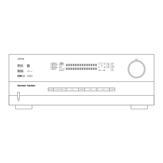
Page 5: Front-Panel Controls
NOTE: To make it easier to follow the instructions that refer to this illustration, a larger copy may be downloaded from the Product Support section for this product at www.harmankardon.com. The following controls and indicators are available on the AVR 630’s front panel: 1 Standby/On Switch... - Page 6 ) Volume Control: Turn this knob clockwise to increase the volume, counterclockwise to decrease the volume. If the AVR 630 is muted, adjusting the volume control will automatically release the unit from the silenced condition.
- Page 7 NOTE: This switch is normally left in the “ON” position. B Headphone Jack: This jack may be used to lis- ten to the AVR 630’s output through a pair of head- phones. Be certain that the headphones have a stan- dard 1/4"...
-
Page 8: Rear-Panel Connections
REAR-PANEL CONNECTIONS REAR-PANEL CONNECTIONS ¡ AM Antenna ™ FM Antenna £ Preamp Outputs ¢ Subwoofer Output ∞ A-BUS Connector § Surround Speaker Outputs ¶ Front Speaker Outputs • Fan Vents ª Center Speaker Outputs ‚ Surround Back/Multiroom Speaker Outputs ⁄ Switched AC Accessory Outlet ¤... - Page 9 (white for front left and red for front right) (+) terminals on the AVR 630 to the red (+) terminals on the speakers and the black (–) terminals on the AVR 630 to the black (–) terminals on the speakers.
- Page 10 REAR-PANEL CONNECTIONS g Remote IR Input: If the AVR 630’s front-panel IR sensor is blocked due to cabinet doors or other obstructions, an external IR sensor may be used. Connect the output of the sensor to this jack. h Remote IR Output: This connection permits the IR sensor in the receiver to serve other remote con- trolled devices.
-
Page 11: Main Remote Control Functions
Lens NOTES: • The function names shown here are each button’s feature when used with the AVR 630. Most buttons have additional functions when used with other devices. When a button is pressed, the function name will appear in the bottom line of the LCD Information Display c. - Page 12 AVR Selector: Pressing this button will switch the remote so that it will operate the AVR 630's functions. If the AVR 630 is in the Standby mode, it will also turn the AVR 630 on. Test Button: Press this button to begin the sequence used to calibrate the AVR 630’s output...
- Page 13 Transport Fast-Play/Scan Buttons: These but- tons have no direct function on the AVR 630, but they are used when the remote is programmed for a com- patible DVD, CD or tape player. Pressing these buttons will transmit a fast-play forward, fast-play reverse, or fast-forward or -reverse scan command, according to the capabilities of the player being controlled.
- Page 14 Lens: The infrared emitters behind the plastic lens at the top of the remote communicate the remote codes to the AVR 630. Be certain that the lens is not covered when using the remote, and point the lens toward the AVR for best results. In learning mode, the remote receives IR codes to be learned through a sensor behind the lens.
-
Page 15: Zone Ii Remote Control Functions
NOTES: • The Zone II remote may be used in either the same room where the AVR 630 is located, or it may be used in a separate room with an optional infrared sensor that is connected to the AVR 630’s Multiroom IR Input f jack. -
Page 16: Installation And Connections
Coaxial Digital Audio Inputs 4. Connect the coaxial or optical Digital Audio Outputs ik on the rear panel of the AVR 630 to the matching digital input connections on a CD-R or MiniDisc recorder. 5. Assemble the AM loop antenna supplied with the unit so that the tabs at the bottom of the antenna loop snap into the holes in the base. -
Page 17: System And Power Connections
Audio Outputs j on the AVR 630’s rear panel. Option 2: Connect the Multiroom Audio Outputs j on the AVR 630 to the inputs of an optional stereo power amplifier. Run high-quality speaker wire from the amplifier to the speakers in the remote room. - Page 18 INSTALLATION AND CONNECTIONS RS-232 Connections The AVR 630 is equipped with an RS-232 Serial Connection Port e that may be used for two pur- poses. When the port is connected to a compatible, optional, external computer, keypad or control system...
-
Page 19: System Configuration
You are now ready to power up the AVR 630 to begin these final adjustments. 1. Make certain that the AC power cord is firmly inserted in to the AC Power Cord Jack ‹... -
Page 20: Input Setup
Be certain to follow the (+) and (–) polarity indicators that are in the battery compartment. 5. Turn the AVR 630 on either by pressing the Standby/On Switch 1 on the front panel, or via the remote by pressing the Power On Button b, the AVR Selector e∫... - Page 21 NOTE: A signal will be sent to this jack only when the input selected for use by the AVR 630 is digital. Digital signals will be passed through regardless of their for- mat, and which digital input (optical or coax) they are fed from.
-
Page 22: Audio Setup
When the SURR BACK line of the SPEAKER SETUP menu (Figure 6) is set to NONE the AVR 630 will be con- figured for 5.1-channel operation, and only the modes appropriate to a five-speaker system will appear. When... -
Page 23: Speaker Setup
BACK TO MASTER MENU line and press the Set Button q. Speaker Setup This menu tells the AVR 630 which type of speakers are in use. This is important as it adjusts the settings that decide whether your system will use the “5- channel”... - Page 24 When this option is selected, all bass infor- mation will be routed to the front left/right “main” speakers. • If a subwoofer is connected to the AVR 630, you have the option to have the front left/right “main” speakers reproduce bass frequencies at all times,...
-
Page 25: Delay Settings
“sweet spot” position. In addition to adjusting the delay time for each individ- ual speaker position, the AVR 630 is among the few A/V receivers that allows you to adjust the delay for the combined output of all speakers as a group. This feature is called A/V Sync Delay;... -
Page 26: Output Level Adjustment
Output level adjustment is a key part of the configura- tion of any surround sound product. It is particularly important for a digital receiver such as the AVR 630, as correct outputs ensure that you hear soundtracks with the proper directionality and intensity. -
Page 27: Manual Output Level Adjustment
Upon completion of the second circulation, the LCD Information Display c will flash COMPLETE three times and then go out. The tone will stop and the AVR 630 will return to normal operation. If you find that the output levels chosen by EzSet are either uncomfortably low or high, you may repeat the procedure. - Page 28 AVR. Once the settings outlined on the previous pages have been made, the AVR 630 is ready for operation. While there are some additional settings to be made, these are best done after you have had an opportunity to lis- ten to a variety of sources and different kinds of pro- gram material.
-
Page 29: Operation
Turning the AVR 630 On or Off • When using the AVR 630 for the first time, you must press the Main Power Switch A to turn the unit on. This places the unit in a Standby mode, as indicated by the amber illumination surrounding the Standby/On Switch 1 . -
Page 30: Surround Mode Selection
(HDTV) system. An optional, external RF demodulator is required to use the AVR 630 to listen to the Dolby Digital sound- tracks available on laser discs. Connect the RF output of the LD player to the demodulator and then connect... -
Page 31: Surround Mode Chart
The Pro Logic mode re-creates original Pro Logic processing for those who prefer that presentation. Logic 7 Cinema Exclusive to Harman Kardon for A/V receivers, Logic 7 is an advanced mode that extracts the maximum surround information from either Logic 7 Music surround-encoded programs or conventional stereo material. - Page 32 You may use any LD or CD player equipped with a digital output to play DTS-encoded discs with the AVR 630. All that is required is to connect the player’s output to either an Optical or Coaxial Input or front panel JL.
- Page 33 DVD player (usually with the “Audio Select” button or in a menu screen on the disc) to send a full 5.1 feed to the AVR 630. It is also possible for the type of signal feed to change during the course of a DVD’s playback.
-
Page 34: Tuner Operation
Digital Audio Outputs ikL. Tuner Operation The AVR 630’s tuner is capable of tuning AM, FM and FM Stereo broadcast stations. Stations may be tuned manually, or they may be stored as favorite station pre- sets and recalled from a 30-position memory. -
Page 35: Output Level Trim Adjustment
Once changed to an output, the setting will remain as long as the AVR 630 is turned on, unless the setting is changed in the OSD menu system, as described above. -
Page 36: Advanced Features
Turn-On Volume Level As is the case with most audio/video receivers, when the AVR 630 is turned on, it will always return to the volume setting in effect when the unit was turned off. However, you may prefer to always have the AVR 630 turn on at a specific setting, regardless of what was last in use when the unit was turned off. -
Page 37: Semi-Osd Settings
Full-OSD Time-Out Adjustment The FULL OSD menu system is used to simplify the setup and adjustment of the AVR 630 by using a series of on-screen menus. The factory default setting for these menus leaves them on the screen for 20 seconds after a period of inactivity before they disap- pear from the screen (Time-Out). -
Page 38: Multiroom Operation
Selector Buttons ç∂d to turn on to a specific source. As long as an IR feed to the AVR 630 has been established from the remote room, using any of the buttons on either remote will control the remote loca- tion volume rî, change the tuner frequency... -
Page 39: Multiroom Operation
Once the Multiroom system is turned on, it will remain on even if the AVR 630 is placed in the Standby mode in the main room by pressing the Power Off Button å or the Main Power Switch A on the front panel. -
Page 40: Configuring The Remote
CD recorders and cassette decks. The codes for other brand devices may be programmed into the AVR 630 remote using its extensive library of remote codes or a head-to-head learning process for codes not in the internal library. -
Page 41: Automatic Code Entry
or too old, and thus not all of its commands will be in the code library. You may fill in the codes for any button that does not operate properly by using the learning technique shown on page 41. Automatic Code Entry In addition to manual code selection using the brand name list, it is also possible to automatically search through all the codes that are stored in the AVR remote’s... -
Page 42: Changing Devices
However, in some circumstances you may have con- figured your system so that the devices connected to the AVR 630 do not correspond to the default device settings and the legends printed on the remote. For example, if your system has two VCRs you may con- nect the second VCR to the VID 2 input. -
Page 43: Macro Programming
“TV,” and show how to change it to take on the codes for operating a VCR. When that device’s name appears, press the Set Button q. O L D D E V I C E T Y P E Figure 37 4. - Page 44 Following the instructions on the remote’s LCD screen, press the first key you wish to be transmitted in the macro. In our example, we first want the AVR 630 to turn on, so the Power Button should be pressed.
-
Page 45: Punch-Through Configuration
For example, if your TV, cable box or satellite receiver is connected through the AVR 630, you will most likely want to use the AVR 630’s volume control commands even when the remote has been set to issue all other commands for the video device. -
Page 46: Ezset Configuration
T V < - T V Figure 65 EzSet Configuration Harman Kardon’s patented EzSet feature makes it easi- er than ever to calibrate the output levels on your new receiver for maximum playback accuracy. In addition to automatically setting the levels, the AVR remote’s LCD display allows the unit to be used as a direct read-out SPL meter. -
Page 47: Renaming
Note that renaming a device in the remote will not change the name of the input used by the on-screen menu system of the AVR 630. NOTES ON RENAMING DEVICES: • To move the cursor to the right or left of the display ‹... -
Page 48: Resetting The Remote
CONFIGURING THE REMOTE Renaming Individual Keys Thanks to the programming flexibility of the AVR remote, an individual button on the remote may be assigned a feature or function that is different from the name that appears as the factory default when the button is pressed. - Page 49 any settings you had previously made will have to be reentered. To erase all settings and reset the remote to the original factory default settings and displays, follow these steps: 1. Press and hold the Program Button about three seconds while the message shown in Figure 17 appears in the remote’s LCD Information Display .
-
Page 50: Troubleshooting Guide
If the system still malfunctions, a system reset may clear the problem. To clear the AVR 630’s entire system memory includ- ing tuner presets, output level settings, delay times and speaker configuration data, first put the unit in Standby by pressing the Standby/On Switch 1. -
Page 51: Technical Specifications
Height measurement includes feet and chassis. All features and specifications are subject to change without notice. Harman Kardon, Power for the Digital Revolution and Logic 7 are registered trademarks of Harman International Industries, Incorporated. is a trademark of Harman International Industries, Incorporated (patent no. 5,386,478). - Page 52 250 Crossways Park Drive, Woodbury, New York 11797 www.harmankardon.com © 2003 Harman International Industries, Incorporated ® Part No. ZK-C11-01HA-00...
Need help?
Do you have a question about the AVR 630 and is the answer not in the manual?
Questions and answers