Advertisement
Quick Links
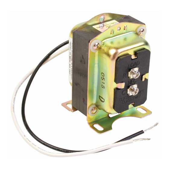
AT120A, AT140A, AT150A, AT175A
Universal Transformers
APPLICATION
These transformers are for use in 24 Vac nominal
control circuits. They are typically used in
heating/cooling control systems but can be used in any
application that does not exceed the load ratings. They
Input
Model
Voltage
Number
(60 Hz)
AT120A
120/208/240
AT140A
120
120/208/240
120/240
208/240
AT150A
120/208/240
AT175A
120/208/240
INSTALLATION
When Installing this Product...
1. Read these instructions carefully. Failure to follow
them could damage the product or cause a haz-
ardous condition.
2. Check the ratings given in the instructions and on
the product to make sure the product is suitable
for your application.
3. Installer must be a trained, experienced service
technician.
4. After installation is complete, check out product
operation as provided in these instructions.
Table 1. Model Specifications.
Primary
Wiring
Connections
9 in. leads
9 in. leads
9 in. leads
9 in. leads
INSTALLATION INSTRUCTIONS
meet National Electrical Code Class 2 "not wet" and
Class 3 "wet" requirements and are Underwriters
Laboratories (UL) Inc. listed under UL 1585. They can be
mounted through a 7/8 in. knockout on the accessory
mounting plate (included), or with the integral mounting
feet. See Table 1 for additional specifications.
Secondary
Voltage
At Rated
Open
Power
Circuit
Output
27.0
24.0
27.0
24.0
27.5
24.0
27.5
24.0
CAUTION
Electrical Hazard.
Can cause electrical shock or equipment
damage.
Disconnect power supply before beginning
installation.
Mounting
The transformer can be mounted in one of three ways:
• foot mounting.
• plate mounting.
• mounting through outlet box knockout hole.
Foot Mounting
1. Mount the transformer using screws (not sup-
plied) through the four 3/16 in. x 3/8 in. holes in
the mounting feet.
2. Make line voltage primary connections within an
approved enclosure. See Fig. 1.
3. Discard the mounting plate.
Wiring
Connections
Screw terminals
Screw terminals
Screw terminals
Screw terminals
Output Rating at
100 Percent
Power Factor
20 VA
40 VA
50 VA
75 VA
69-0251-04
Advertisement

Related Manuals for resideo AT120A


Summary of Contents for resideo AT120A
- Page 1 AT120A, AT140A, AT150A, AT175A Universal Transformers INSTALLATION INSTRUCTIONS meet National Electrical Code Class 2 “not wet” and APPLICATION Class 3 “wet” requirements and are Underwriters Laboratories (UL) Inc. listed under UL 1585. They can be These transformers are for use in 24 Vac nominal mounted through a 7/8 in.
- Page 2 AT120A, AT140A, AT150A, AT175A UNIVERSAL TRANSFORMERS PLATE MOUNTED AT CLAMP ON PRIMARY END BELL MOUNTING PLATE SCREW TERMINALS FOR SECONDARY BELL CONNECTIONS LEADWIRES FOR PRIMARY CONNECTIONS USE SCREWS OR BOLTS THROUGH SLOTS (4) IN MOUNTING FEET SCREW TERMINALS FOR SECONDARY...
- Page 3 AT120A, AT140A, AT150A, AT175A UNIVERSAL TRANSFORMERS WITH RAISED PORTION OF KNOCKOUTS FACING YOU: PRY UP TOP SECTION OF LARGE KNOCKOUT BY INSERTING SCREWDRIVER FIRST AT ONE SIDE OF SLOT AND THEN AT THE OTHER SIDE. M12126 Fig. 3. When screw is tightened, clamp holds plate on transformer.
- Page 4 Resideo Technologies, Inc. 1985 Douglas Drive North, Golden Valley, MN 55422 1-800-468-1502 69-0251—04 M.S. Rev. 08-20 | Printed in United States www.resideo.com © 2020 Resideo Technologies, Inc. All rights reserved. This product is manufactured by Resideo Technologies, Inc. and its affiliates.
Need help?
Do you have a question about the AT120A and is the answer not in the manual?
Questions and answers