
Related Manuals for Kohler RSB Series


Summary of Contents for Kohler RSB Series
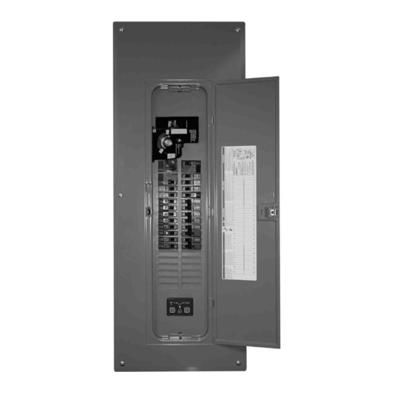
- Page 1 Operation Automatic Transfer Switches Model: Intelligent Transfer Switch 150--225 Amps Electrical Controls: MPACt 550 TP-6487 8/07a...
-
Page 2: Product Identification Information
Product Identification Information Product identification numbers determine service parts. Record the product identification numbers in the spaces below immediately after unpacking the products so that the numbers are readily available for future reference. Record field-installed kit numbers after installing the kits. -
Page 3: Table Of Contents
Table of Contents Product Identification Information ............Safety Precautions and Instructions . - Page 4 Table of Contents, continued Section 4 Accessories ..............Accessory Board .
-
Page 5: Safety Precautions And Instructions
Safety Precautions and Instructions IMPORTANT SAFETY INSTRUCTIONS. Accidental Starting DANGER Electromechanical equipment, including generator sets, transfer WARNING switches, switchgear, and accessories, can cause bodily harm and pose life-threatening danger when improperly installed, operated, or Hazardous voltage. maintained. To prevent accidents be Will cause severe injury or death. - Page 6 Notice WARNING NOTICE Hardware damage. The transfer switch both American Standard and metric hardware. Use the correct size tools to prevent rounding of the bolt heads and nuts. Airborne particles. cause severe injury blindness. Wear protective goggles and clothing when using power tools, hand tools, or compressed air.
-
Page 7: Introduction
Type 3R load centers and the transfer switch Information in this publication represents data available conversion kit. Figure 2 lists the available manuals and at the time of print. Kohler Co. reserves the right to part numbers. change this literature and the products represented... -
Page 8: Model Code
MPACt 550 electrical controls rated at 240 volts/60 Hz, 2 poles, 3 wires, and solid neutral in a type 1 enclosure with a 200 amp main circuit breaker, a 125 amp generator circuit breaker, and no load shed modules. Model Kohler Mechanism SB: Intelligent Transfer Switch, Service Entrance Rated Electrical Controls... -
Page 9: Service Assistance
Visit the Kohler Power Systems website at Phone: (86) 21 6288 0500 KohlerPower.com. Fax: (86) 21 6288 0550 Look at the labels and stickers on your Kohler product India, Bangladesh, Sri Lanka or review the appropriate literature or documents India Regional Office included with the product. - Page 10 Notes Service Assistance TP-6487 8/07...
-
Page 11: Section 1 Description
TV technician for help. 1.2 Intelligent Transfer Switch Do not make changes or modifications to the transfer equipment that are not expressly approved by Kohler The Model RSB Intelligent Transfer Switch is intended Co. Any changes or modifications may result in the for use in an optional standby power system to allow a loss of authority to operate the equipment. -
Page 12: Specifications
1.3 Specifications Enclosure Type Rating, Amps Load Center Weight, kg (lb) H x W x D, mm (in.) NEMA 1 150–225 40 circuits 11.40 (25.0) 1000 x 362 x 95 (39.37 x 14.25 x 3.74) NEMA 3R 100–200 28 circuits 19.10 (42.0) 858 x 375 x 115 (33.78 x 14.76 x 4.53) Figure 1-2... -
Page 13: Section 2 Operation
Section 2 Operation 2.1 Introduction and provides connections for remote test and remote exercise inputs. See Section 4.1 for information on the Red and green LEDs on the transfer switch controls accessory board. indicate which sources are available, show which source is connected to the load, and flash to indicate 2.2 Pushbuttons and Indicators fault conditions. -
Page 14: Source Sensing
2.3 Source Sensing Normal power source voltage falls below 80% of nominal The transfer switch controller monitors the utility power source voltage and initiates the transfer sequence if the source voltage falls below the voltage dropout setting. Undervoltage dropout time delay, Retransfer is initiated when the utility source rises above 0.5 seconds (fixed) the voltage pickup settings and remains stable for at... -
Page 15: Time Delays
2.4.1 Time Delays The Failure to Acquire Standby Time Delay is set for 78 seconds to match the crank cycle of the Kohler The controller time delays are shown in Figure 2-6. For generator set controller. adjustable time delays, install the accessory board. See Section 4.1. -
Page 16: Running A Test
Note: Resetting the controller clears the exerciser To start a loaded test: setting. Set the exercise time and day as Press and hold the Test button for 6 seconds, until the described in Section 2.8 after resetting the standby source available and standby position LEDs controller. -
Page 17: Unloaded Exercise
2.8.1 Unloaded Exercise To start a loaded exercise AND set the exercise timer: During an unloaded exercise, the generator set runs but On the day and time that you want the exercise to run the electrical load is not transferred from the normal every week (for example, at 1 p.m. - Page 18 Notes Section 2 Operation TP-6487 8/07...
-
Page 19: Section 3 Scheduled Maintenance
Section 3 Scheduled Maintenance 3.1 Introduction DANGER Regular preventive maintenance ensures safe and reliable operation and extends the life of the transfer switch. Preventive maintenance includes periodic testing, cleaning, inspection, and replacement of worn Hazardous voltage. or missing components. Section 3.4 contains a service Will cause severe injury or death. -
Page 20: Testing
Short circuits. Hazardous voltage/current can cause Observe the indicator LEDs included on the transfer severe injury or death. Short circuits can cause bodily injury switch to check their operation. and/or equipment damage. Do not contact electrical connections with tools or jewelry while making adjustments or Watch and listen for signs of excessive noise or repairs. -
Page 21: Other Inspections And Service
Internal Inspection. Open the door and inspect 3.3.2 Other Inspections and Service system components monthly or when any condition Have an authorized distributor/dealer perform periodic noticed during an external inspection may have affected inspections, scheduled maintenance, and service to internal components. ensure the safe and reliable operation of the transfer switch. -
Page 22: Service Schedule
3.4 Service Schedule Follow the service schedule below for the recommended service intervals. Activities designated by an X may be performed by the switch operator. Have all other maintenance and service performed by an authorized distributor/dealer. Adjust, Visually Repair, Section Inspect Check Replace System Component or Procedure... -
Page 23: Section 4 Accessories
Section 4 Accessories 4.1 Accessory Board DANGER Hazardous voltage. Will cause severe injury or death. Disconnect all power sources before opening the enclosure. The optional accessory board is mounted with standoffs on the controller’s main logic board. See Figure 4-1 for the accessory board location and components. -
Page 24: Accessory Board Time Delay Adjustment Switches
4.1.2 Accessory Board Time Delay Maintained/Momentary Test, Switch 3. Set this switch for a maintained or momentary remote test Adjustment Switches (start/stop) switch, as follows: The 10-position rotary switches allow adjustment of the ON (maintained) position: close a remote test switch time delays shown in Figure 4-2. -
Page 25: Load Shed Kit
4.2 Load Shed Kit The load shed kit includes one or two load shed modules which connect to remote-controlled branch circuit The optional load shed kit disconnects selected loads breakers (sold separately). Type 1 enclosures can have before transfer to the emergency source, reducing the one or two load shed modules installed. - Page 26 Notes Section 4 Accessories TP-6487 8/07...
- Page 27 Appendix A Abbreviations The following list contains abbreviations that may appear in this publication. A, amp ampere cubic feet per minute est. estimated ABDC after bottom dead center center of gravity E-Stop emergency stop alternating current cubic inch displacement etc. et cetera (and so forth) analog to digital centerline...
- Page 28 Motoren-und Turbinen-Union read only memory kilobyte (2 bytes) megawatt rot. rotate, rotating KBus Kohler communication protocol milliwatt revolutions per minute μF kilogram microfarad right side kg/cm kilograms per square N, norm. normal (power source) remote terminal unit...
- Page 29 Notes TP-6487 8/07...
- Page 30 Notes TP-6487 8/07...
- Page 32 For the nearest sales/service outlet in the US and Canada, phone 1-800-544-2444 KohlerPower.com Kohler Power Systems Asia Pacific Headquarters TP-6487 8/07a 7 Jurong Pier Road Singapore 619159 E 2007 by Kohler Co. All rights reserved. Phone (65) 6264-6422, Fax (65) 6264-6455...
Need help?
Do you have a question about the RSB Series and is the answer not in the manual?
Questions and answers