Table of Contents
Advertisement
Quick Links
Advertisement
Table of Contents

Summary of Contents for Licht MFC-200/N
- Page 1 Level Monitor model MFC-200/N Technical Manual Licht...
-
Page 2: Table Of Contents
Contents Introduction Front panel indication Configuration Programmable parameters Current outputs MODBUS protocol Specifications Housing Connection diagrams Configuration sheet MODBUS registers Rev. B0 (20–05–08) MFC-200/N Technical Manual... -
Page 3: Introduction
12 configurable relays, 6 isolated configurable current loop outputs and up to 2 failure indication relays. The MFC-200/N shares its form factor with other Licht controllers for transformers, such as the MFC-200/R voltage regulator and the MFC-200/P parallelism controller. Like all Licht controllers, the MFC-200/N was designed for use under severe conditions, including high temperatures, electromagnetic interference, surges, impulses and overvoltage. -
Page 4: Front Panel Indication
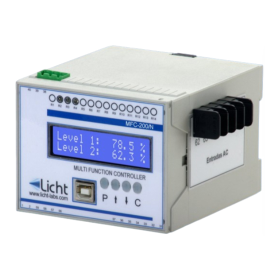
2 Front panel indication During operation, the MFC-200/N alternates each channel’s level indication, presented as a percentage value. This indication depends on the calibration performed by the user before commisioning. A timer automatically changes the channel on display. The user may manually alter the currently displayed channel (skipping the alternation timer) by pressing the keys. -
Page 5: Configuration
3 Configuration Parameterization The MFC-200/N features 4 keys to access its functions. The procedure to configure any parameter is as follows: 1. Press the P key to enter the parameters menu. 2. Using the keys, choose the desired parameter. -
Page 6: Programmable Parameters
4 Programmable parameters The MFC-200/N was developed to provide the user with the greatest possible flexiblity, such that all supervision and configuration can be executed on-site or remotely through the existing communication channels. We define all user-configurable parameters as follows: Parameter: Set Point[1-12] Options: 0 to 100%, in 1% increments. -
Page 7: Current Outputs
8E1: 8 data bits, even parity, 1 stop bit. 8O1: 8 data bits, odd parity, 1 stop bit. 8N2: 8 data bits, no parity, 2 stop bits. Parameter: Address Options: 1 to 247. Description: MODBUS address for the MFC-200/N. Rev. B0 (20–05–08) MFC-200/N Technical Manual... -
Page 8: A Specifications
8N1, 8E1, 8O1, 8N2 2 lines with 16 characters each (5 mm). Displays LCD with backlight. 10 A @ 250 Vac, 0.5 A @ 125 Vdc Relays Galvanic Isolation: 1.5 kV, 60 Hz, 1 min. Rev. B0 (20–05–08) MFC-200/N Technical Manual... -
Page 9: B Housing
Licht http://www.licht-labs.com info@licht-labs.com B Housing Rev. B0 (20–05–08) MFC-200/N Technical Manual... -
Page 10: C Connection Diagrams
Licht http://www.licht-labs.com info@licht-labs.com C Connection diagrams Rev. B0 (20–05–08) MFC-200/N Technical Manual... - Page 11 Import considerations a. The MFC-200/N and the supervisor system must be connected using shielded twisted pair (STP) cables. b. The RS-485 pair must be terminated in both ends by 120 Ω resistors. c. The RS-485 devices must be connected in a bus topology. No other network topol- ogy (tree, star, ring, etc.) is acceptable.
-
Page 12: D Configuration Sheet
Activation Logic Normal, Inverted Relay 1 to 12 Set Point 0 to 100% Hysteresis 1 to 50% Delay 0.1 to 25.5 min. Associated Channel 1 to 6 Forced Activation Normal, Activated Activation Logic Normal, Inverted Rev. B0 (20–05–08) MFC-200/N Technical Manual... -
Page 13: Emodbus Registers
Current Loop - Output Scale 0: 0-1 mA 1: 0-5 mA 2: 0-10 mA 3: 0-20 mA 4: 0-20 mA 201-206 Level [1-6] 0.0 to 100.0% Relay State [1-12] 0: disabled 221-232 1: enabled Rev. B0 (20–05–08) MFC-200/N Technical Manual... - Page 14 Licht http://www.licht-labs.com info@licht-labs.com Rev. B0 (20–05–08) MFC-200/N Technical Manual...
Need help?
Do you have a question about the MFC-200/N and is the answer not in the manual?
Questions and answers