Table of Contents
Advertisement
Quick Links
Advertisement
Table of Contents

Summary of Contents for Électronique du Mazet ECHODIA ELIOS
- Page 1 USER GUIDE ELIOS CHODIA a brand of Électronique du Mazet ZA Route de Tence 43520 Le Mazet Saint Voy FRANCE Tél. : +33 4 71 65 02 16 Email : contact@electroniquedumazet.com Firmware 2.7.0x Web : www.electroniquedumazet.com Software 2.4.0.x ECH001XN111-A4 – 07/2022...
- Page 2 Instructions for use & Technical description Please read these instructions carefully before using your new device! This manual is an integral part of the device and must be kept until it is destroyed. This equipment has been designed and manufactured for use in otologic diagnosis.
-
Page 3: Table Of Contents
Table of contents Information and safety ................................5 About this manual ..............................5 Presentation of the device ............................5 1.2.1 Intended Use .............................. 6 1.2.2 Target population ............................6 1.2.3 Expected performance ..........................6 1.2.4 Contraindications ............................6 1.2.5 Side effects ..............................6 1.2.6 Units of measurement .......................... - Page 4 Handheld mode measurement ............................. 43 Patient management ............................... 43 4.1.1 Create a new patient ..........................43 4.1.2 Patient follow-up ............................44 ABR ..................................45 4.2.1 Clinical mode ............................45 4.2.2 Screening mode ............................47 4.2.3 Measurement consultation ........................50 4.2.4 Screening consultation ..........................
- Page 5 6.1.8 Real-time signal and rejection ........................ 102 6.1.9 cVEMP muscular contraction level ....................... 103 6.1.10 Measurement consultation ......................... 104 6.1.11 Visualization settings and print options ..................... 105 6.1.12 Management of the measurement groups ..................106 6.1.13 Markers .............................. 107 6.1.14 Special functionality for ECochG ......................
-
Page 6: Information And Safety
Chapter 1 Information and safety 1.1 About this manual ELIOS This user and maintenance manual is published to help you to get started with your device from the initial receipt, through commissioning, use and maintenance. If you have any difficulty in understanding this manual, contact your dealer/distributor or the manufacturer, Élec- tronique du Mazet. -
Page 7: Intended Use
1.2.1 Intended Use ELIOS is primarily intended for ENT doctors working in private practice or in a hospital environment. The ELIOS is able to integrate all the measures modules of our range of otologic diagnostic device, however it can accom- modate other healthcare professionals. -
Page 8: Units Of Measurement
1.2.6 Units of measurement For all these devices, the units of measurement are expressed in the units of the international system: Unit Base unit Name Symbol Frequency Hertz Voltage Tension Intensity (Decibel) Sound pressure level dB SPL Hearing level dB HL 1.2.7 Accessories This device is delivered with the following accessories as standard: - Mini-USB cable 2m... -
Page 9: Warnings
Surface electrodes 20x25mm (20 pcs) 40112 Spes Medica Surface electrodes F40 (30 pcs) 302062 Skintact Foam eartips ER3-14A 13mm (50 pcs) 40116 Foam eartips ER3-14B 10mm (50 pcs) 40117 Eartips for insert earphones ER3-14E 4mm (20 pcs) 40119 Etymotic Eartips for insert earphones ER3-14D 3.5mm (20pcs) 40118 Etymotic Gold eartips ER3-26A 13mm (20 pcs) -
Page 10: Potential Risks
CAUTION: the computer must never be located in a space accessible to the patient CAUTION: Be sure to follow the maintenance instructions listed in the 6.Maintenance and servicing CAUTION: The battery can only be replaced by Électronique du Mazet technicians or their distributors. -
Page 11: Applicable Symbols
It is preferable to charge/discharge the battery as fully as possible to ensure a long service life. Charge the device to its maximum capacity and only charge it when it has reached a critical battery level. To disconnect the device from the power supply, the USB power adapter must be disconnected. 1.6 Applicable symbols Front side Name of the device... -
Page 12: Identification Label
Recycling: This device should be disposed of at an appropriate collection and recycling facility. Consult the manufacturer. Direct current Serial number Manufacturer Year of manufacture Country of production Product reference CE marking 1.7 Identification label Information and specifications are given on the back of each device on an identification label: Device : Device identification label ELIOS... -
Page 13: Patient Data Confidentiality
1.8 Patient data confidentiality The device collects data. It is the practitioner's responsibility to apply and comply with the European Parliament's General Data Protection Regulation 2016/679. When returning the device to the after-sales service, the user must delete the patient data from it so that it is not disclosed. The practitioner has the possibility to make a backup copy of the data ECHOSOFT by saving them in the software (see section 0) before deleting the patients from the device (see section... -
Page 14: General Information About Using Elios
Chapter 2 ELIOS General information about using 2.1 Initial Start-up of the device 2.1.1 Switching on / starting The device can be turned on without any other part connected (OAE probe, EchoDif). Turn on the power using the switch on top of the device (if it does not start, make sure the device's battery is charged) 2.1.2 Touch screen calibration For the first start-up, it is necessary to calibrate the touch screen. -
Page 15: Home Screen
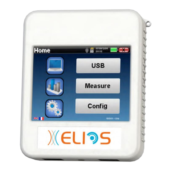
General information about using ELIOS 2.1 Initial Start-up of the device 2.1.4 Home screen Once this step completed, the homepage appears: Several items of information appear on this page. First, it contains the 3 possible selection parameters when the device is starting: •... -
Page 16: General Device Configurations
General information about using ELIOS 2.2 General device configurations 2.2 General device configurations Some of the device general operating parameters can be configured. Accordingly, it is possible to set the time, date, brightness and orientation of the screen. To do this, just enter the configuration menu from the main screen. -
Page 17: Advanced Configurations
General information about using ELIOS 2.3 Advanced configurations The «About» menu contains the contact details of the company Electronique du Mazet. The “Calibration” menu allows the consultation of the acoustic calibration values defined for your device. Electronique du Mazet Don't modify this value, only or your reseller are approved to realize this cali- bration. - Page 18 General information about using ELIOS 2.3 Advanced configurations Config DP-gram : Access to the DP-gram measurement settings Config TEOAE : Access to the TEOAE measurement settings Protected access to settings : if the checkbox is selected, the access to the configuration (DPgram and TEOAE) directly from the measurement screen is locked, as well as the parameters in screening mode.
-
Page 19: Configuration Of The Click Stimulus
General information about using ELIOS 2.3 Advanced configurations If you have any doubt about the configuration, click on "Reset data" to return the factory configuration and "Confirm”. 2.3.1.2 Config TEOAE If you are not familiar with the settings and how modifying them can affect the test results, do not try to change them. -
Page 20: Selection Of The Connected Jack Headphone
General information about using ELIOS 2.3 Advanced configurations • Click: Used for adjusting the interval between the physical power of the clicks (dB SPL) and the perceived intensity (dB HL) (25 by default). The adjusted coefficient corresponds to: Emitted power (dB HL) = Set power (dB SPL) + X (dB SPL) •... -
Page 21: Introduction And Test Setup
Chapter 3 Introduction and test setup 3.1 ABR ABR: Auditory Brainstem Response Auditory Brainstem Response, also known as brainstem auditory evoked potentials are widely used both in the field of neu- rological exploration and ENT. It is a non-invasive electrophysiological technique based on the principle of electroenceph- alography (EEG), it provides objective test, reproducible information about the auditory function, from the cochlea to the brainstem. -
Page 22: Equipment
Introduction and test setup 3.1 ABR 3.1.1 Equipment To make a ABR measurement you need the following equipment: Common elements for all configurations ELIOS unit unit Electrophysiology 4 surface electrodes cable Measurement with insert earphone 2 foam ear tips ER3-14A 13mm 2 foam ear tips ER3-14B 10mm Insert earphone 2 insert earphone tips ER3-14E 4mm... -
Page 23: Patient Setup
Introduction and test setup 3.1 ABR 3.1.2 Patient setup Using an otoscope, make sure that the ear canal is not obstructed by ear-wax. This operation must be carried out by a qualified person. These instructions must be adapted depending of the ear(s) tested, in every case the color corresponds to the right... - Page 24 Introduction and test setup 3.1 ABR electrode (Patient Reference) is far less strict. This electrode can be placed on the forehead, on the temple or on the chin. • The electrodes must be attached behind the ear to be tested (on the mastoid) •...
-
Page 25: Ecochg
Introduction and test setup 3.2 ECochG 3.2 ECochG ECochG: ElectroCochleoGraphy Among the Auditory Brainstem Response, we group together the Brainstem Auditory Evoked Potentials (ABR) and the Cochlear or Electrocochleographic potentials (ECochG). Traditionally, ECochG was carried out under anesthesia using a trans-eardrum invasive electrode placed on the promontory. -
Page 26: Patient Setup
Introduction and test setup 3.2 ECochG 2 gold ear tips ER3-26A 13mm 2 gold ear tipsER3-26B 10 mm 3.2.1 Patient setup Using an otoscope, make sure that the ear canal is not obstructed by ear-wax. This operation must be carried out by a qualified person. These instructions must be adapted depending of the ear(s) tested, in every case the color corresponds to the... - Page 27 Introduction and test setup 3.2 ECochG electrode (Patient Reference) is far less strict. This electrode can be placed on the forehead, on the temple or on the chin • Connect the electrode in the middle of the forehead (minus) with the Black clip and the Patient Reference with Green...
-
Page 28: Vemp
Introduction and test setup 3.3 VEMP 3.3 VEMP Otholithic Evoked Potentials (OEP) or Myogenic Vestibular Evoked Potentials the (VEMP) are sacculo-collique reflex rec- orded in response to an acoustic stimulation. They study the sacculo –spinal way: the sacculo, the inferior vestibular nerve to the sterno-cleido-mastoid (SCM) ipsilateral via the cervical spinal cord. -
Page 29: Patient Setup
Introduction and test setup 3.3 VEMP Measurement with DD45 headphone DD45 headphone 3.3.1 Patient setup Using an otoscope, make sure that the ear canal is not obstructed by ear-wax. This operation must be carried out by a qualified person. These instructions must be adapted depending of the ear(s) tested, in every case the color corresponds to the right... - Page 30 Introduction and test setup 3.3 VEMP 3.3.1.1 cVEMP • Attach an electrode Patient Reference in the middle of the forehead, just below the hairline. The other electrode, (minus) is placed on the sternum. • The electrodes must be placed on the sternocleidomastoid muscles. To make measurement on both ears easier, it is recommended to equip one ear at a time because the meas- urement position is hard to hold when the electrodes and clips are on both sides.
- Page 31 Introduction and test setup 3.3 VEMP 3.3.1.2 oVEMP • Attach an electrode (Patient Reference) in the middle of the forehead, just below the hairline. Put two wall-aligned electrodes under the eyes. • The V+ will be the closest to the eye, the other one, Minus (V-), just below. For measurement on both sides, the switch between is automatic, however, you must physically switch the V- electrode.
-
Page 32: Assr
Introduction and test setup 3.4 ASSR 3.4 ASSR ASSR : Auditory Steady-State Responses The Auditory Steady-State Responses (ASSR) is an electrophysiology measurement used to determine the hearing loss degree with a specificity in frequency. The sound stimuli (500Hz, 1000Hz, 2000Hz and 4000Hz) are presented with modulation frequencies sufficiently spaced so that their physiological responses do not interfere with each other. - Page 33 Introduction and test setup 3.4 ASSR Computer + software USB cable ECHOSOFT Measurement with insert earphone 2 foam ear tips ER3-14A 13mm 2 foam ear tips ER3-14B 10mm Insert earphone 2 insert earphone tips ER3-14E 4mm 2 insert earphone tips ER3-14D 3.5mm Measurement with insert earphone and acoustic tube Ecouteurs 2 Bouchons OAE T04 tree...
-
Page 34: Patient Setup
Introduction and test setup 3.4 ASSR 3.4.1 Patient setup Using an otoscope, make sure that the ear canal is not obstructed by ear-wax. This operation must be carried out by a qualified person. These instructions must be adapted depending of the ear(s) tested, in every case the color corresponds to the right... - Page 35 Introduction and test setup 3.4 ASSR • Connect the electrode in the middle of the forehead (minus) with the Black clip and the Patient Reference with the Green clip. The clip must be connected to the electrodes placed behind the Right ear and the Blue...
-
Page 36: Dpmc (Hydrops)
Introduction and test setup 3.5 DPMC (Hydrops) 3.5 DPMC (Hydrops) DPMC: Cochlear Microphonic Potential Phase Shift The cochlea, a peripheral hearing organ, contains outer hair cell (OHC) which play a part in the amplification of acoustic signals because of their contracting property. By applying an acoustic stimulation to the ear, more particularly by a tone burst at a frequency of 1 kHz, we will stimulate "the"... -
Page 37: Patient Setup
Introduction and test setup 3.5 DPMC (Hydrops) 2 electroacoustic tubes 2 surface electrodes 2 gold ear tips ER3-26A 13mm 2 gold ear tipsER3-26B 10 mm 3.5.1 Patient setup Using an otoscope, make sure that the ear canal is not obstructed by ear-wax. This operation must be carried out by a qualified person. - Page 38 Introduction and test setup 3.5 DPMC (Hydrops) ELIOS • Connect the earphone Mini-DIN to the «Audio» connector of the unit. Connect the ECHO-DIF Mini- DIN on the AUX connector. • Clean the surface of the skin where the electrodes will be attached with abrasive gel. This decreases the impedance of the skin.
-
Page 39: Otoacoustic Emission (Shift-Oae, Dp-Gram And Teoae)
Introduction and test setup 3.6 Otoacoustic emission (Shift-OAE, DP-gram and TEOAE) 3.6 Otoacoustic emission (Shift-OAE, DP-gram and TEOAE) The cochlea, the peripheral organ of hearing, is capable of emitting low-amplitude sounds in response or not to acous- tic stimulation. These sounds are easily recorded in the external auditory canal using a sensitive miniaturized microphone. The genesis of these sounds coming from the cochlea, called otoacoustic emission, depends on the proper functioning of specific cells in the cochlea: the outer hair cells (OHC). -
Page 40: Teoae
Introduction and test setup 3.6 Otoacoustic emission (Shift-OAE, DP-gram and TEOAE) 3.6.3 TEOAE TEOAE : Transient otoacoustic emissions. When we speak about otoacoustic emissions, we primarily think about the transient otoacoustic emissions also called TEOAE which are most used in clinical examination. The OAE are recorded by a small probe placed in the external ear canal. - Page 41 Introduction and test setup 3.6 Otoacoustic emission (Shift-OAE, DP-gram and TEOAE) Check that the 3 small holes at the end of the probe are not blocked. If necessary, replacement tips are deliv- ered with the unit. Using an otoscope, make sure that the ear canal is not obstructed by ear-wax. This operation must be carried out by a qualified person.
-
Page 42: Audiometry
Introduction and test setup 3.7 Audiometry 3.7 Audiometry Audiometry is the basic review of hearing. This test allows a quick check of hearing, from the transmission chain to the brain. The measure is obtained through the emission of a calibrated frequency sound wave, of which we will lower the level until the patient can't hear it anymore. -
Page 43: Setup
Introduction and test setup 3.7.2 Setup Using an otoscope, make sure that the ear canal is not obstructed by ear-wax. This operation must be carried out by a qualified person. ELIOS • To make measurement with headset, connect the cable on the Jack plug of the (indicated with the headset icon). -
Page 44: Handheld Mode Measurement
Chapter 4 Handheld mode measurement 4.1 Patient management ELIOS offers ideal measurement organization thanks to an advanced patient-based management system. From the home page, select the "Measure" mode, lead- ing to the choice of seeking an existing patient or creat- ing a new one. -
Page 45: Patient Follow-Up
Handheld mode measurement 4.1 Patient management Here, the information about the patient is kept brief. You can enter more details when you export the data to the ECHOSOFT program. Refer to paragraph Erreur ! Source du renvoi introuvable. 4.1.2 Patient follow-up After you have created the patient, his or her record is recorded on the memory card. -
Page 46: Abr
Handheld mode measurement 4.2 ABR 4.2 ABR Refer to paragraph Erreur ! Source du renvoi introuvable. to obtain the necessary instructions about the needed equipment and the setup. ABR module provides two measurement modes. The first is the clinical mode allowing ABR thresholds with an accesses to several options that allow some flexibility in making tests. - Page 47 Handheld mode measurement 4.2 ABR The impedance values must be as small and well bal- anced as possible to guarantee measurement quality. If value V- is greater than 7kΩ, wipe the patient’s forehead again and reattach new electrodes. If value V+ is greater than 7kΩ, check that the mastoid electrode is properly placed. If necessary, wipe the patient’s mastoid again and reattach new electrodes.
- Page 48 Handheld mode measurement 4.2 ABR Rejection indicator Power Graph area of the previous measure Normality area for waves : Graph area of the I, III et V current measure Number of averaging Two curves are displayed. The bottom curve is the curve being constructed and its shape is updated in real-time depending on the number of clicks already fed into the patient's ear.
- Page 49 Handheld mode measurement 4.2 ABR • Button “Wiring”: show an illustration on how to put the electrodes on the newborn Classical 4 points setup Simplified 3 points setup • «Tube» : tick the box if you use the acoustic stimulator with tube. Select «Right»...
- Page 50 Handheld mode measurement 4.2 ABR The ABR measurement window opens, click on "Start". The measure will begin, ensure that the patient is not too agitated during the measurement. Two stacked curves are displayed, they are built turn by turn. This measurement method enables to calculate the correlation between the two curves.
-
Page 51: Measurement Consultation
Handheld mode measurement 4.2 ABR 4.2.3 Measurement consultation Refer to paragraph for more details about patient management. Selection of the marker to Additional options be placed Power and ear I, III, V automatic positioning Scroll through measures Change graph time scale Select ears to be displayed When consulting an ABR, the following window appears and is a way of processing the curves. - Page 52 Handheld mode measurement 4.2 ABR A second click on the “Latency” button enables to dis- play a latency graph for the I, III and V waves. The "Delta" option displays a table summarizing the Delta results between the left and right measurement waves (at the same intensity).
-
Page 53: Screening Consultation
Handheld mode measurement 4.2 ABR 4.2.4 Screening consultation Refer to paragraph for more details about patient management. Additional options Wave V automatic position- Measure validation Change graph time scale Measure informations When consulting a screening ABR, the above window is displayed and allows to process the curves. The first aim of a screening ABR is to locate the wave V at a relatively low power. -
Page 54: Ecochg
Handheld mode measurement 4.3 ECochG 4.3 ECochG Refer to paragraph Erreur ! Source du renvoi introuvable. to obtain the necessary instructions about the needed equipment and the setup. 4.3.1 Setting up measurement parameters Once the clinical ECochG diagnosis type has been se- lected its configuration window appears. - Page 55 Handheld mode measurement 4.3 ECochG The time signal appears on the screen. The indicator light at the top left indicates whether the signal has reached the rejection threshold (◼ = threshold reached, ◼ = signal below threshold). The rejection level is de- termined in %.
-
Page 56: Measurement Consultation
Handheld mode measurement 4.3 ECochG For more details about the curve consulting options, please refer to paragraph Erreur ! Source du renvoi introuvable.. The saved data can be consulted in the patient's "Consultation" menu. If a new measurement is run, the process is the same as the one described above. - Page 57 Handheld mode measurement 4.3 ECochG The "->" button at the top right gives access to another toolbar. The "Ratio" option displays a table summarizing the ra- tios between SP and AP on all the curves. The percent- age ratio is obtained with the following formula: ����...
-
Page 58: Vemp
Handheld mode measurement 4.4 VEMP 4.4 VEMP Refer to paragraph to obtain the necessary instructions about the needed equipment and the setup. ECHOSOFT On the device, only cVEMP are available, to make oVEMP, please use the software refer to paragraphe 6.1. 4.4.1 Setting up measurement parameters Once the clinical VEMP diagnosis type has been se- lected its configuration window appears. - Page 59 Handheld mode measurement 4.4 VEMP The time signal appears on the screen. The indicator light at the top left indicates whether the signal has reached the rejection threshold (◼ = no muscle contrac- tion, not enough contractions, = enough contractions to perform the measurement). There are three levels of rejection to better adapt to the level of contraction that the patient can provide.
-
Page 60: Measurement Consultation
Handheld mode measurement 4.4 VEMP The impedance is displayed to verify that the electrode placed on the sterno-cleido-mastoid muscle of the other ear is correctly in place. For more details about the curve consulting options, please refer to paragraph Erreur ! Source du renvoi introuvable.. - Page 61 Handheld mode measurement 4.4 VEMP The "Latency" option replaces the graphics by a table summarizing the temporal placement of each markers. Finally, the "Curve" option is used for selecting the curves one by one in order to display them on a full-screen. This gives a more detailed curve, for instance, to place the markers more accurately.
-
Page 62: Dpmc
Handheld mode measurement 4.5 DPMC 4.5 DPMC Refer to paragraph to obtain the necessary instructions about the needed equipment and the setup. 4.5.1 Paramétrage de la mesure Once the clinical DPMC diagnosis type has been se- lected its configuration window appears. It is a way of adjusting the parameters appearing in the following ta- ble. - Page 63 Handheld mode measurement 4.5 DPMC The patient must be as relaxed as possible during this stage. ◼ The rejection level must be set so that the indicator light is activated when the patient blinks his eyes or swallows. At rest, it should not be activated more than one or 2 times per second.. Click on the "Save"...
-
Page 64: Measurement Consultation
Handheld mode measurement 4.5 DPMC You can suspend acquisition at any time using the "Pause" button. This temporarily suspends acquisition when the patient has a fit of coughing for instance, or to facilitate changes of the patient's position. The rejection indicator light notifies you when the rejection threshold is reached. If 40 successive rejections are de- tected, the current point is rejected and the "Rejection"... - Page 65 Handheld mode measurement 4.5 DPMC 1. The index given above is the phase shift value in degrees. 2. The index, indicated in white below, is the ratio between the effective signal and the average noise in dB (S/N). To validate a point, this value must be greater than 6dB. •...
- Page 66 Handheld mode measurement 4.5 DPMC Point spectral analysis To run the spectral analysis of the signal by a Fast Fou- rier Transform (FFT) click on the "Freq" button. The power distribution graph (abscissa) with respect to the frequency (ordinate) appears. The effective spectral energy zone is indicated by a vertical white line.
-
Page 67: Shift-Oae
Handheld mode measurement 4.6 Shift-OAE 4.6 Shift-OAE Refer to paragraph to obtain the necessary instructions about the needed equipment and the setup. 4.6.1 Setting up measurement parameters Once the clinical Shift-OAE diagnosis type has been selected its configuration window appears. It is a way of adjusting the parameters appearing in the following ta- ble. - Page 68 Handheld mode measurement 4.6 Shift-OAE 4.6.2.1 OAE probe self calibration When the measurement begins, a series of calibrations are performed automatically to determine if the measurement conditions are optimal to obtain usable results. In this context, the system may asks the user to make choices in order to adjust the measurement parameters as best as possible: •...
- Page 69 Handheld mode measurement 4.6 Shift-OAE 1. The green curve represents the effective signal. 2. The red curve represents the average noise level. 3. The 2 indexes displayed on the right are the Minimum/Maximum values of the effective and average noise signals.
-
Page 70: Measurement Consultation
Handheld mode measurement 4.6 Shift-OAE 4.6.3 Measurement consultation Refer to paragraph for more details about patient management. Phase shift between A and B Phase curve Min / Max signals Measure informations Select phase shift calculation marker This graph contains several items of information : •... - Page 71 Handheld mode measurement 4.6 Shift-OAE 4.6.3.1 Advanced analysis tools ELIOS includes a high-performance tool palette that giving you the opportunity of analyzing directly on the touch screen (without any computer support), all the data you have collected. Click on one of the points of the curve. A window including a data analysis table appears. It contains several items of information concerning the investigated signal.
-
Page 72: Dp-Gram
Handheld mode measurement 4.7 DP-gram 4.7 DP-gram Refer to paragraph to obtain the necessary instructions about the needed equipment and the setup. 4.7.1 Measurement settings Once the clinical DP-gram diagnosis type has been se- lected its configuration window appears. It is a way of adjusting the parameters appearing in the following ta- ble. - Page 73 Handheld mode measurement 4.7 DP-gram • "Low signal. Check leak. Continue?": The signals F1 and F2 and are too low compared to their set value (at least 20dB too low). This may be due to the wrong positioning of the probe, more precisely a sealing problem between the probe plug and the ear canal.
-
Page 74: Screening Mode
Handheld mode measurement 4.7 DP-gram 4.7.2 Screening mode In the "Screening" mode it is not possible to adjust the number of stimulations. In this mode the device switches to the next frequency when the validation con- ditions are reached or after having reached the maxi- mum test duration. -
Page 75: Measurement Consultation
Handheld mode measurement 4.7 DP-gram 4.7.3 Measurement consultation Refer to paragraph for more details about patient management. dB SPL scale Frequencies in Hz Signal level validation indicator Noise level Signal level in dB SPL Stimulation power PASS/REFER indicator (only in screening mode) Validation protocol This graph contains several items of information: •... - Page 76 Handheld mode measurement 4.7 DP-gram Point spectral analysis To run spectral analysis of the signal by a Fast Fourier Transform (FFT) click on the "Freq" button. The power distribution graph (abscissa) with respect to the frequency (ordinate) appears. The effective spectral energy zone is indicated by a vertical white line.
-
Page 77: Teoae
Handheld mode measurement 4.8 TEOAE 4.8 TEOAE Refer to paragraph to obtain the necessary instructions about the needed equipment and the setup. 4.8.1 Measurement settings Once the clinical TEOAE diagnosis type has been se- lected its configuration window appears. It is a way of adjusting the parameters appearing in the following ta- ble. - Page 78 Handheld mode measurement 4.8 TEOAE 5dB to strong). This may be due to the wrong positioning of the probe, more precisely if the probe is to deep in the ear canal. It is advised to click on “No”, reposition the probe and restart the measure. However, if you are sure of the probe’s positioning, it is possible to continue by clicking “Yes”.
- Page 79 Handheld mode measurement 4.8 TEOAE 4.8.2 Screening mode In the "Screening" mode it is not possible to adjust the stimulation rate (fixed at 80Hz). In this mode the device stops the measurement when the validation criteria are satisfied. On the other hand, if the maximum test dura- tion is reached, the measurement is stopped and the de- vice indicates a non-conclusive test.
-
Page 80: Measurement Consultation
Handheld mode measurement 4.8 TEOAE 4.8.3 Measurement consultation Refer to paragraph for more details about patient management. Repeatability between Signal level (dB SPL) Signal/noise ratio for buffer A and B for Stimulus curve each frequency each frequency Noise level (dB SPL) Information about Measurement infor- Display stimulus cuve... -
Page 81: Audiometry
Handheld mode measurement 4.9 Audiometry 4.9 Audiometry Refer to paragraph to obtain the necessary instructions about the needed equipment and the setup. When you start a new diagnosis, the configuration window appears. It allows to start new measurement of pure-tone Audiometry or speech Audiometry. - Page 82 Handheld mode measurement 4.9 Audiometry The “Settings” button opens a window allowing you to set the level of the masking noise as well as the starting power of the automatic protocols. Click “OK” to con- firm After selecting the ear (right or left), the «Start» button became available. Click on it to start the measurement. Measurement The Tone audiometry window open.
- Page 83 Handheld mode measurement 4.9 Audiometry The icon of a floppydisk at the bottom right of the screen is used for recording the parameters defined above. They then become the default parameters for this type of measurement. The “Settings” button opens a window allowing you to set the level of the masking noise as well as the starting power of the automatic protocols.
-
Page 84: High Frequency Audiometry
Handheld mode measurement 4.9 Audiometry To build the curve you have to specify the patient answer with the “Yes” “No” buttons for each stimulation (activated thanks to the “stim” button). You can see the curve at any time by pressing the “Graph” button. Then you can save the curve by clicking on“Save”, delete it by exiting the window or continue the measure by clicking on one of the boxes in the summary table. -
Page 85: Speech Audiometry
Handheld mode measurement 4.9 Audiometry 4.9.3 Speech audiometry Measurement settings When you start a new diagnosis, the configuration window appears. It lets you choose the type of list used, for example the disyllabic lists of Fournier. ELIOS is designed to allow you to easily perform a Speech audiometry. At the launch of the test, the device displays the words from the list on the screen. - Page 86 Handheld mode measurement 4.9 Audiometry Measurement From the launch window of the test, set the power and the ear to be tested before launching a “series” by clicking on “Start”. Speech audiometry begins, the word currently spoken is written in red. If the patient correctly repeats the word, click on it to validate the answer.
-
Page 87: Measurement Consultation
Handheld mode measurement 4.9 Audiometry 4.9.4 Measurement consultation Refer to paragraph for more details about patient management. Switch between Go back to start new Switch Go back to start pure tone and measurement graph new measurement speech audiometry • The « Measure » button resumes the measurement and keep the already recorder information in displayed on the curves. -
Page 88: General Information About Software Echosoft
Chapter 5 General information about software ECHOSOFT 5.1 Minimum configuration needed Intel or AMD – Dual Core 2 Ghz Processor RAM memory Free space on hard drive Display 1280*720 1 port USB 2.0 Operating system Windows 7/8/10/11, Mac OSX Power supply Class II compliant with EN 60601-1 5.2 Installation 5.2.1 Installing the software... -
Page 89: Installation Des Pilotes Usb
General information about software ECHOSOFT 5.2 Installation Then you can choose the location where the application files will be installed. By default, it is "C:/Program Files/Echodia/EchoSoft" Click on “Install” and then “close” to complete the installation. Once the software is launched, the following window appears: 5.2.2 Installation des pilotes USB ELIOS has a generic USB driver mass storage, it is rec-... -
Page 90: Patient Management
General information about software ECHOSOFT 5.3 Patient management 5.3 Patient management ECHOSOFT ELIOS software is capable of reading measurements made using . it incorporates a database in which the patient data and measurements can be stored. 5.3.1 Create new patient After installing the software, there is no patient in the database, before starting a new measurement, a patient must be created. - Page 91 General information about software ECHOSOFT 5.3 Patient management 5.3.2.1 Add a patient to the datebase Select the patient(s) to be imported from the list, then click on "Save to database". The software will then ask you for the information for the whole selection before importing the data. To register a patient in the database, it is necessary to indicate the doctor or the operator who performed the measurements.
-
Page 92: Delete A Patient
General information about software ECHOSOFT 5.3 Patient management If you select some patients in the list before launching the registering in the database, the software only synchronizes the patients that have been selected. If you have a large amount of patient stored on the de- vice, making a selection enables to synchronize rapidly your data. -
Page 93: Settings
General information about software ECHOSOFT 5.4 Settings 5.4 Settings ECHOSOFT offers a range of configurations to ad- just the software’s operation to your needs. The “Set- tings” are available on the menu located at the top of the main window. The setting window is composed of tabs that gives ac- cess to different categories of configuration detailed be- low. -
Page 94: Medical Software
General information about software ECHOSOFT 5.4 Settings 5.4.1 Medical software This section is used to configure a third-party patient management software to import audiometry curves. A first drop-down menu lets you select the software used. Next, you must define the location where the ECHOSOFT software will retrieve the patient infor- mation. -
Page 95: Impression
General information about software ECHOSOFT 5.5 Update 5.4.3 Impression ECHOSOFT There is two printing model in , one with a full note taking page first and measure results on the others pages (standard layout) and another model with the measure results first and the potential notes at the bottom of the page (compact layout). -
Page 96: Measurement Consultation On Echosoft
General information about software ECHOSOFT 5.6 Measurement consultation on ECHOSOFT ELIOS 5.5.1 update ELIOS If your is connected in USB mode to your com- ECHOSOFT puter, when the software is launched, a verification of your version is performed. If a newer ver- sion is available, the software offers you to automati- cally update. -
Page 97: Measurement On Echosoft
Chapter 6 ECHOSOFT Measurement on ECHOSOFT ELIOS gives ability to use the as a peripheral to make measurement and diagnostic directly from your computer (PC or Mac). ECHOSOFT See subsection to install and needed driver to make measurement. ECHOSOFT Start the , the window below appears. -
Page 98: Evoked Potential Modul (Abr, Ecochg Et Vemp)
Measurement on ECHOSOFT 6.1 Evoked potential modul (ABR, ECochG et VEMP) ECHO- To optimize the life length of the battery, the screen will turn off after two minutes when you use the SOFT . To turn it back on, click on the “On/Off” button 6.1 Evoked potential modul (ABR, ECochG et VEMP) See subsection Erreur ! Source du renvoi... -
Page 99: Manual Mode
Measurement on ECHOSOFT 6.1 Evoked potential modul (ABR, ECochG et VEMP) 8. Settings for curves consultation (for more details, see Erreur ! Source du renvoi introuvable.) “Save” button to save the current measurement session and button to start a new session. 9. - Page 100 Measurement on ECHOSOFT 6.1 Evoked potential modul (ABR, ECochG et VEMP) ELIOS User guide ECH001XN111-A4 – 07/2022...
-
Page 101: Script Mode
Measurement on ECHOSOFT 6.1 Evoked potential modul (ABR, ECochG et VEMP) 6.1.4 Script mode This measurement mode enables to fully define a protocol. You can pre-set measurements by adjusting the order of the ears tested, the powers, or the type of stimulation. Protocols thus defined are saved and can be re-loaded at any time. You can create as many protocols as you want. -
Page 102: Abr Screening Mode
Measurement on ECHOSOFT 6.1 Evoked potential modul (ABR, ECochG et VEMP) 150µs clic Burst at 1000Hz 3/3/3 Start of the recording Time in µs Time in µs 6.1.5 ABR screening mode Among the tests of the evoked potentials module, the screening mode is only available for the ABR. This measure- ment mode is intended for newborns. -
Page 103: The Advanced Options
Measurement on ECHOSOFT 6.1 Evoked potential modul (ABR, ECochG et VEMP) 6.1.6 The Advanced options This tab gives access to two kind of settings : • Settings about acoustique stimulation to 3) : (This setting only applies for manual mode and automatic mode). 1. -
Page 104: Impedances Check And Measurement Progress
Measurement on ECHOSOFT 6.1 Evoked potential modul (ABR, ECochG et VEMP) 6.1.7 Impedances check and measurement progress This panel is used to control the impedances, the pro- gress of the measurement and to visualize/modify the active stimulator. The impedance values should be as small (< 5kΩ) and as balanced as possible to ensure the quality of the measurement. -
Page 105: Cvemp Muscular Contraction Level
Measurement on ECHOSOFT 6.1 Evoked potential modul (ABR, ECochG et VEMP) 6.1.9 cVEMP muscular contraction level The cVEMP rejection is based on the contraction of the sternocleidomastoid muscle (SCM) and is therefore dependent on the patient. It is necessary to adjust it at each measurement. The gauge at the bottom left of the screen shows the pa- tient's muscle contraction level. -
Page 106: Measurement Consultation
Measurement on ECHOSOFT 6.1 Evoked potential modul (ABR, ECochG et VEMP) This procedure is to be repeated when you change ear side 6.1.10 Measurement consultation The consultation window of the evoked potentials module looks like this: 1. Select the measure type and the display mode. There are several display modes: •... -
Page 107: Visualization Settings And Print Options
Measurement on ECHOSOFT 6.1 Evoked potential modul (ABR, ECochG et VEMP) 6.1.11 Visualization settings and print options 1. The label of each curve indicates several information about the test performed: the ear tested (red = right and blue = left), the power, the stimulus (and the frequency for the Burst) and the ipsilateral noise level (if used). The right click on the label gives access to the note editor, which allows you to write comments that will be displayed in front of the curve 2. -
Page 108: Management Of The Measurement Groups
Measurement on ECHOSOFT 6.1 Evoked potential modul (ABR, ECochG et VEMP) 13. The organization of the curves on the graph is based on the stimulation power indicated on these labels. There are 4 sorting options: • Centered (superpose all curves on the center) •... -
Page 109: Markers
Measurement on ECHOSOFT 6.1 Evoked potential modul (ABR, ECochG et VEMP) 6.1.13 Markers The positioning of the markers is an essential part of the analysis of the results. These markers help the operator to analyze the amplitude and latency of specific points on the curve. Add a marker: right-click on the graph display area, the contextual menu is displayed allowing you to select the marker to be placed. -
Page 110: Special Functionality For Ecochg
Measurement on ECHOSOFT 6.1 Evoked potential modul (ABR, ECochG et VEMP) 6.1.14 Special functionality for ECochG Select the « Alone » display mode and select a measurement. 1. Graph display area : The first curve corresponds to the one selected in (4), the other two curves are displayed by selecting "simultaneous display"... -
Page 111: Screening Abr" Window
Measurement on ECHOSOFT 6.1 Evoked potential modul (ABR, ECochG et VEMP) 6.1.15 «Screening ABR» window The Screening ABR window provides a quick view of the ear and power as well as whether or not the screening is validated. 1. Power set for this measurement. 2. -
Page 112: Assr
Measurement on ECHOSOFT 6.2 ASSR 6.2 ASSR See subsection to obtain the necessary instructions about the needed equipment and the setup. The measurement window looks like this: 1. Settings specific to the measurement (see 0). 2. Show impedances, connected stimulator and rejection rate (see 6.2.1). 3. -
Page 113: Measurement Setting
Measurement on ECHOSOFT 6.2 ASSR 6.2.2 Measurement setting 1. Preset management. These presets save the state of all the options contained in this panel. By default, the software is delivered with 3 presets. These presets are not editable, however, you can create your own presets and save them. -
Page 114: Measurement Progress
Measurement on ECHOSOFT 6.2 ASSR 6.2.3 Measurement progress 1. Indicates, for each frequency being recorded, the signal level (in green) compared to the noise level (in red). It corresponds to the signal at the modulation frequency and the surrounding noise. The more the signal comes out of the noise, the more the measurement will tend to validate a response. -
Page 115: Measurement Results
Measurement on ECHOSOFT 6.2 ASSR 6.2.4 Measurement results The ASSR measurement results come in two forms. First, the validation results for the different intensities for each frequency and for each ear. Then, an extrapolation of these results is displayed in the form of an audiometry graph. You can switch between these two displays by using the tabs at the top of the window. - Page 116 Measurement on ECHOSOFT 6.2 ASSR Progress of the validation Validation level through time for each inten- sity (from 0 to 100%) Time in minutes In this example, we can see that the intensities 60 and 40dB are quickly validated, on the other hand, at 20dB the validation took practically 10 minutes.
-
Page 117: Hydrops (Shift-Oae And Dpmc)
Measurement on ECHOSOFT 6.3 Hydrops (Shift-OAE and DPMC) 6.3 Hydrops (Shift-OAE and DPMC) See subsection 3.5(DPMC) or 3.6(Shift-OAE) to obtain the necessary instructions about the needed equipment and the setup. The measurement window looks like this: 1. Measurement configuration frame. There are small changes between shift-OAE and DPMC setting (see subsection 6.3.1) 2. - Page 118 Measurement on ECHOSOFT 6.3 Hydrops (Shift-OAE and DPMC) ELIOS User guide ECH001XN111-A4 – 07/2022...
- Page 119 Measurement on ECHOSOFT 6.3 Hydrops (Shift-OAE and DPMC) Recommended values for measurement settings Shift-OAE DPMC Power Between 60 and 75 dBSPL, gap L1 L2 = 0 Between 80 and 90 dBSPL Stim number Minimum 40 Minimum 100 Frequency 1200±150 Hz 1000±50 Hz 1.
-
Page 120: Description Of The Measurement Window
Measurement on ECHOSOFT 6.3 Hydrops (Shift-OAE and DPMC) If the Left, Right and Minus values are greater than 7kΩ, check that the clamps and electrophysiology ca- ble are properly connected, check that the "Patient Reference" electrode is properly attached. In case these values are less than 10kΩ but are balanced (deviation <±2kΩ), the measurement is possible, but the results may be degraded. - Page 121 Measurement on ECHOSOFT 6.3 Hydrops (Shift-OAE and DPMC) The scale of the phase graph is within ±180, but the measured value may exceed these limits. In this case, the points have their phase reversed (±360°), appearing on the opposite edge of the graph. In most cases, this effect can be corrected by centering the curve (see item 7).
-
Page 122: Advanced Analysis Tools
Measurement on ECHOSOFT 6.3 Hydrops (Shift-OAE and DPMC) 6.3.3 Advanced Analysis Tools ELIOS ECHOSOFT As the , the offer an advanced analysis tool for each phase point. For this purpose, select «point analysis» (see item 6 in measurement window Erreur ! Source du renvoi introuvable.) then double click on the point to be analyzed. -
Page 123: Dp-Gram
Measurement on ECHOSOFT 6.4 DP-gram 6.4 DP-gram See subsection to obtain the necessary instructions about the needed equipment and the setup. 6.4.1 Description of the measurement window For details about presentation and analysis of the curves, see section Erreur ! Source du renvoi introuvable.. -
Page 124: Description Of The Measurement Window
Measurement on ECHOSOFT 6.4 DP-gram 6.4.2 Description of the measurement window 1. Graphic display area: • X-axis: frequency. • Y-axis: Power. • Green curve: effective signal power. • Black numbers: value in dB of the effective signal power. • Red curve: noise power. 2. -
Page 125: Bilateral Display
Measurement on ECHOSOFT 6.4 DP-gram 6.4.3 Bilateral display It is possible to display and print a left and a right measurement at the same time. To do this, press the "Show both sides" button on the test page. Another possibility is to select a first measurement, then hold down the "Ctrl" key on the keyboard and select a measurement on the opposed side in the measurement browser window. -
Page 126: Advenced Analysis Tool
Measurement on ECHOSOFT 6.4 DP-gram 6.4.4 Advenced analysis tool ELIOS ECHOSOFT As the , the offer an advanced analysis tool for each DP-gram point. For this purpose, double click on the point to be analyzed. Time-related graphic of data corresponding to the selected point. Frequency-related graphic of data corresponding to the selected point. -
Page 127: Teoae
Measurement on ECHOSOFT 6.5 TEOAE 6.5 TEOAE See subsection to obtain the necessary instructions about the needed equipment and the setup. 6.5.1 Description of the measurement window For more details about presentation and analysis of the measurement, refer to subsection Erreur ! Source du renvoi introuvable.. -
Page 128: Description Of The Measurement Window
Measurement on ECHOSOFT 6.5 TEOAE 6.5.2 Description of the measurement window Temporal click graphic A and B (buffer) temporal curve graphic as well as the noise one • Red: buffer A • blue: buffer B • green: noise (A-B) Click frequency graphic Noise frequency graph (red) and signal frequency graph (green) Measurement setting information Table of the signal on noise ratio and repeatability rate at different frequencies... -
Page 129: Bilateral Display
Measurement on ECHOSOFT 6.5 TEOAE 6.5.3 Bilateral display It is possible to display and print a left and a right measurement at the same time. To do this, press the "Show both sides" button on the test page. Another possibility is to select a first measurement, then hold down the "Ctrl" key on the keyboard and select a measurement on the opposed side in the measurement browser window. -
Page 130: Audiometry
Measurement on ECHOSOFT 6.6 Audiometry 6.6 Audiometry See subsection Erreur ! Source du renvoi introuvable. to obtain the necessary instructions about the needed equip- ment and the setup. 6.6.1 Pure tone audiometry By default, the audiometry starts up on the Pure Tone mode. It is possible to change the mode via the tabs at the top left of the window. -
Page 131: Speech Audiometry
Measurement on ECHOSOFT 6.6 Audiometry 8. The whole green area is dedicated to the masking noise. In the upper part, the power and frequency band of the noise are indicated. Just below, the box "Continuous masking" allows to have a permanent masking (if it is not checked, the masking starts at the same time as the stimulation). -
Page 132: Use Of The Microphone
Measurement on ECHOSOFT 6.6 Audiometry 5. This button allows you to import new lists on the software (If you have no list installed, click on this button to import lists previously downloaded from http://echodia.fr/firmware/vocal/). 6. This option will pause the list after each word. 7. -
Page 133: Description Of The Measurement Window
Measurement on ECHOSOFT 6.6 Audiometry 6.6.4 Description of the measurement window 1. Display area of the pure tone audiometry graph: • Abscissa: frequency in Hz. • Ordinate: power in dB HL. • The blue curve with crosses is for aerial measurement on the left ear. •... -
Page 134: Masking Calculation Help
Measurement on ECHOSOFT 6.6 Audiometry 6.6.5 Masking calculation help The fourth tab of the audiometry window gives access to the patient's measurement history. A double click on the date of the measurement will display it in the background (in transparency) to compare the current measurement with the selected one. - Page 135 Measurement on ECHOSOFT 6.6 Audiometry 6.6.5.1 Color code • Yellow (with the differential value indicated): frequencies that needs to be retested with contralateral masking. • Blue : currently selected frequency. In « Speech » audiometry, no frequency will be selected, the module will apply the appropriate masking for speech audiometry •...
-
Page 136: Merge Measurement
Measurement on ECHOSOFT 6.6 Audiometry Efficiency criteria: Differential = Rinne_CtL (the highest) + 10dB − AI_AC Maximum masking level: Max masking ( Insert ) = best ipsilateal BC threshold + AI_AC + 5 6.6.6 Merge measurement There are two ways for displaying two measurements on the same graph: Select the measurement in «... - Page 137 Measurement on ECHOSOFT 6.6 Audiometry ELIOS User guide ECH001XN111-A4 – 07/2022...
-
Page 138: Using Keyboard Shortcuts
Measurement on ECHOSOFT 6.6 Audiometry 6.6.7 Using keyboard shortcuts In addition to the visual controls on the software, you can perform the audiometry manually with the keyboard of your computer. Use the computer Validate patient Varying the power of microphone to speek Switch stimulation response the masking noise... -
Page 139: Maintenance And Servicing
Chapitre 7 Maintenance and servicing 7.1 Periodic checks Before testing, consider checking: • The presence of the acoustic stimulus and the correct power calibration. • The absence of interference in the incoming signals. • The general functioning of the device. Replace the unit and its peripherals in the original case after each use. -
Page 140: Accessories
Maintenance and servicing 7.3 Malfuction 7.2.2 Accessories In order to ensure perfect hygiene, it is essential to systematically clean all material and equipment in direct contact with the patient. All consumables (surface electrodes and ear tips) are disposable, discard them after use. Erreur ! The references of the consumables compatible with your device are listed in the subsection Source du renvoi introuvable.. -
Page 141: After-Sales Service And Warranty
Maintenance and servicing 7.3 Malfuction 7.3.2 After-sales service and warranty This device is guaranteed by your supplier under the conditions specified in this document, provided that: ▪ Only accessories supplied or qualified by Électronique du Mazet should be used ▪ Any modification, repair, extension, adaptation and adjustment of the product must be carried out by Élec- tronique du Mazet or its distributors for these operations. -
Page 142: Transport And Storage
Maintenance and servicing 7.4 Transport and storage 7.4 Transport and storage When transporting and storing the device, it must be carefully stored in the case in which it was delivered its original packaging) or in packaging that protects it from external damage. Store in a clean, dry place at room temperature 7.5 Disposal As soon as any deterioration is detected, the product must be cleaned with a broad-spectrum disinfectant and returned... -
Page 143: Technical Specifications
Chapter 8 Technical specifications 8.1 General technical characteristic of the device Devices intended for use in locations where the ambient pressure is outside the range of 98kPa and 104kPa must be recalibrated to the location in question, under typical ambient pressure and temperature conditions, to avoid a shift in reference sound pressure levels. -
Page 144: Test Parameters
Technical specifications 8.1 General technical characteristic of the device 8.1.1 Test parameters : Measurement Characteristic - Acoustic stimulation: from 1 kHz to 3 kHz - Digital resolution 16 bits @ 32kHz Shift-OAE (DPOAE) - Sound intensity: 50 to 75 dB SPL - Acoustic stimulation: 900Hz to 1100Hz - Specific earplug - Digital resolution 16 bits @ 32kHz... - Page 145 Technical specifications 8.1 General technical characteristic of the device Narrow band masking noise Central Maximum Maximum Maximum frequency Lower cut-off Upper cut-off power. power. power. (Hz) (Hz) (Hz) (dB EM) (dB HL) (dB HL) min = -10 dB EM min = -10 dB HL min = -10 dB HL 1 000 1 120...
-
Page 146: Standards/Certifications
Technical specifications 8.2 Standards/Certifications 8.2 Standards/Certifications 8.2.1 EMC compliance table EMC compliance according to IEC 60601-1-2 (2014) 4th Edition (EN 60601-1-2: 2015) The Echodia range of products are intended for use in the electromagnetic environment specified below. The customer or user of the equipment should ensure that it is used in such an environment. Emissions testing Compliance Electromagnetic environment - guidelines... - Page 147 Technical specifications 8.2 Standards/Certifications Portable and mobile RF communications equipment should not be used closer to any part of the equipment, including ca- bles, than the recommended separation distance calculated from the equation ap- plicable to the transmitter frequency. Separation distance recommended RF disturbances con- 3 Vrms...
-
Page 148: Ce Declaration
Technical specifications 8.3 Manufacturer 8.2.1 CE declaration ÉLECTRONIQUE DU MAZET can provide the CE declaration for this device on request. The first affixing of the medical CE mark under the responsibility of the company Électronique du Mazet dates from October 2019. Previously, the CE marking of this product was affixed by the company ECHODIA. 8.3 Manufacturer Électronique du Mazet is a company located in the heart of the Massif Central. - Page 149 Lexique DPMC Déphasage des Potentiels Microphoniques Cochléaires Phase shift of Cochlear Microphonic Potential DPOAE Produits de Distorsion des Otoémissions Acoustiques Distortion Product Otoacoustic Emission Shift-OAE Déphase des Produits de Distorsion des Otoémissions Acoustiques Phase shift of Distortion Product Otoacoustic Emission DPgramme Graphique des Produits de Distorsion des Otoémissions Acoustiques DP-gram...
- Page 150 Your dealer / distributor ELIOS User guide ECH001XN111-A4 – 07/2022...
- Page 151 ELIOS ECH001XN111-A4 – 07/2022 Certificate of Guarantee This form must be returned to Electronique du Mazet within 15 days of installation or receipt of the equipment. I, ................Organization: ............Address: ....................................... Declares that it has received the device ......n° ....in working order. I have received all the necessary instructions for its use, maintenance, care, etc...
Need help?
Do you have a question about the ECHODIA ELIOS and is the answer not in the manual?
Questions and answers