
Subscribe to Our Youtube Channel
Related Manuals for Phoenix Mecano HARTMANN ELECTRONIC VME64x Basic 1U

Summary of Contents for Phoenix Mecano HARTMANN ELECTRONIC VME64x Basic 1U
- Page 1 VME64x Basic 1U, 2U and 4U User's Manual https://www.hartmann-electronic.com/ Rev. 1.3...
- Page 2 Rev: R 1.0 19.04.2010 R 1.1 09.08.2011 R 1.2 17.10.2012 R 1.3 20.04.2021 Impressum: Hartmann Electronic GmbH Motorstraße 43, D-70499 Stuttgart (Weilimdorf) Telefon + 49 711 1 39 89-0 Telefax + 49 711 8 66 11 91 E-mail info@hartmann-electronic.com Internet info@hartmann-electronic.com Hartmann Electronic is a longstanding partner of the embedded industry and has a variety of different backplanes.
-
Page 3: Table Of Contents
Table of Contents Applicability ............................1 Background Information ......................1 Safety ............................... 2 Intended Application ......................... 2 Safety Symbols ......................... 2 General Safety Precautions ......................2 Safety Instructions ........................3 2.4.1 Protection Against Electromagnetic Interference (EMI) ............3 2.4.2 Electrostatic Discharge Precautions ................... 3 2.4.3 Installation ........................ - Page 4 4.4.2 Powering the Subrack ..................... 23 4.4.3 Installing Boards ......................24 4.4.4 Installing Filler Panels ..................... 24 Maintaining the Subrack ........................25 Replacing the Fan Tray ......................25 Replacing the Air Filter ......................25 Replacing the Power Supply ..................... 26 Service ............................
-
Page 5: Applicability
1 Applicability System name Order number VME64x Basic 1 U 84 HP Depth 283 mm LMH0000200 VME64x Basic 1 U 84 HP Depth 283 mm with fan tray LMH0000312 VME64x Basic 2 U 84 HP Depth 283 mm LMH0000170 VME64x Basic 2 U 84 HP Depth 283 mm with fan tray LMH0000240 VME64x Basic 4 U 84 HP Depth 283 mm LMH0000180... -
Page 6: Safety
2 Safety 2.1 Intended Application The VME64x System Platform Basic subracks is intended as a platform for a microcomputer system based on the VME64x Standard ANSI/VITA 1.1- 1997 VME64x System Platform Basic subracks are not end-products, so there is no valid approval for this unit. -
Page 7: Safety Instructions
2.4 Safety Instructions The intended audience of this User's Manual is system Integrators and hardware/software engineers. The product has been designed to meet relevant standard industrial safety requirements. It must not be used except in its specific area of office telecommunication industry and industrial control. -
Page 8: Mounting Considerations
Shelf ambient temperature may not exceed 40°C. 2.4.7 Mounting Considerations During the course of handling, shipping, and assembly, parts could become loose or damaged. Do not operate a shelf in this condition, as this may cause damage to other equipment. 2.4.8 Electrical Hazards The caution label on the system's rear near the grounding studs shows that you have to create an earth connection because there may be a high leakage current which is... -
Page 9: Product Description
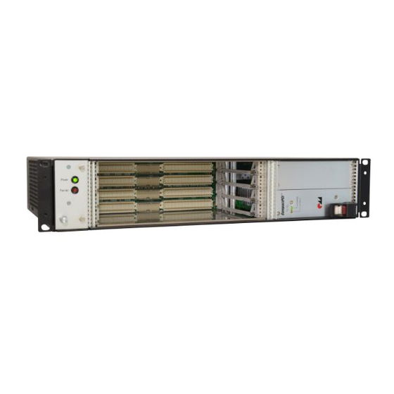
3 Product Description 3.1 System Overview 3.1.1 VME64x Basic 1 U 84 HP VME64x card rack, 1U Power entry module with switch, fuse and filter VME64x backplane: 6 + 3 U, 2 slot Front panel 8 HP 3 U with EMC gasket CompactPCI power supply unit 250 W 3 DC fans: 40 x 40 x 28 mm, Figure 3-1 VME64x Basic 1 U 84 HP with 4 DC fans... -
Page 10: Vme64X Basic 2 U 84 Hp
3.1.3 VME64x Basic 2 U 84 HP VME64x card rack, 2U Power entry module with switch, fuse and filter VME64x backplane: 6 + 3 U, 4 slot Front panel 16 HP 3 U with EMC gasket CompactPCI power supply unit 250 W 3 DC fans: 80 x 80 x 25 mm, Front panel 8 HP 3 U with EMC gasket Figure 3-3 VME64x Basic 2 U 84 HP with 3 DC fans... -
Page 11: Vme64X Basic 4 U 84 Hp
3.1.5 VME64x Basic 4 U 84 HP VME64x card rack, 4U Power entry module with switch, fuse and filter VME64x backplane: 6 + 3 U, 8 slot Front panel 32 HP 3 U with EMC gasket 2 x CompactPCI power supply unit 250 W 6 DC fans: 80 x 80 x 25 mm, 2 x Front panel 8 HP 3 U with EMC gasket Figure 3-5 VME64x Basic 4 U 84 HP with 6 DC fans... -
Page 12: Subrack
3.2 Subrack VME64x subrack, black coating outside (RAL9005), shielded with IEEE guide rails and ESD clip mounted on the right side. 3.3 Backplane All Hartmann VMEbus boards are based on the HIGH-SPEED DESIGN concept. Low reflection is achieved by means of uniform signal line surge impedance. Shielding of each individual signal line assures minimal coupling and therefore guarantees trouble-free operation even when expanded to the 64-bit mode with the 2e protocol (160 MByte/s). -
Page 13: Temperature Sensors And Fan Control
3.3.2 Temperature sensors and fan control For 2U and 4U systems is a temperature-dependent fan control integrated. The fan speed will be controlled by external temperature sensors (NTC). Three or six temperature sensors are located on the left-hand side on the backplane. NTC fan 1 - Slot 1, NTC fan 2 - Slot 2, NTC fan 3 - Slot 3, etc. -
Page 14: Fan Signal Connector
2900 min 3000 2000 1450 min 1000 Temperature (°C) Figure 3-9 Fan characteristic dip-switch on/off 3.3.4 Fan signal connector For subracks assembled with a fan tray, the fan signals are also provided by a 14 pole connector. Signal +12V +12V +12V Fan Load OUT Fan_tacho_4... -
Page 15: Backplane Vme64X 9U 2 Slot (6U) + 1 X Psu 47P (3U)
3.3.5 Backplane VME64x 9U 2 slot (6U) + 1 x PSU 47p (3U) Figure 3-11 Backplane VME64x 9U 2 slot (6U) + PSU 47p (3U) front / rear 3.3.6 Backplane VME64x 9U 4 slot (6U ) + 2 x PSU 47p (3U) Figure 3-12 Backplane VME64x 9U 4 slot (6U) + 2 x PSU 47p (3U) front / rear 3.3.7 Backplane VME64x 9U 8 slot (6U) + 4 x PSU 47p (3U) Figure 3-13 Backplane VME64x 9U 8 slot (6U) + 4 x PSU 47p (3U) front / rear... -
Page 16: Electrical Connection And Power Supply
3.4 Electrical Connection and Power Supply 3.4.1 Power Entry Module The power input module is provided with an IEC 320-C14 connector, integrated Filter, fuseholder 1-pole and Line Switch 2-pole. Technical Data Ratings IEC 1 - 10 A @ Ta 40 °C / 250 VAC; 50 Hz Ratings UL/CSA 1 - 8 A @ Ta 40 °C / 250 VAC;... -
Page 17: Grounding/Protective Earthing
Subrack systems LMH0000200, LMH0000312, LMH0000170, and LMH0000240 are delivered with fuse: 5x20mm 250V/6,3A T m. UL/CSA: Subrack systems LMH0000180 and LMH0000260 are delivered with fuse: 5x20mm 250V/10A T m. UL/CSA Caution! The fuse values (6,3A T, 10A T) are only for incoming inspection. The final values depends on the ready configuration of the completed system, e.g. -
Page 18: Power Supply
3.4.3 Power Supply The power supply has the following main features: • 250W 3U x 8HP • Meet IEC 61000-3-2 harmonic correction • Internal OR-ing diodes for N+1 redundancy • Hot - swappable • Third-wire current sharing • EMI meet EN 55022 / FCC class A •... -
Page 19: Figure 3-16 Ac Power Supply 3U, 250W
Circuit Topology Forward circuit. Transient Response Peak transient less than 100mV and recovers within 2mS after 25% load-change. Safety Standard IEC 60950-1 Class I. Construction Eurocard 3U X 8HP X 160mm CompactPCI format Operating Temperature 0 to +50 °C at full load with specified air flow. Derates linearly to 50% at +70 °C. -
Page 20: Cooling
3.5 Cooling The VME64x front and rear I/O boards are cooled by forced air convection through up to six VDC axial fans. The operating temperature is from 0°C to 40°C. 3.5.1 Airflow Airflow from left to right. Caution! To ensure proper air flow within the system make sure that all slots are populated with either boards or filler panels. -
Page 21: Fans
3.5.2 Fans VME64x Basic Systems with build-in fans In the VME64x Basic Systems with build-in fans, the speed will be controlled by an external thermistor. VME64x Basic 1 U 84 HP Depth 283 mm LMH0000200 VME64x Basic 2 U 84 HP Depth 283 mm LMH0000170 VME64x Basic 4 U 84 HP Depth 283 mm LMH0000180... - Page 22 Dimensions: 40mm x 40mm, 28mm thick Rated Voltage: Rated Current 0.23A Rated Input: 2.76W Rated Speed: 9000rpm Air Flow: 16.6 cfm (0.47 m³/min) Static Pressure: 103Pa (0.414 inchH Noise: 32.8dB(A) Operating Temperature -10°C - +60°C (Non-condensing) Storage Temperature -30ºC to +70ºC Life Expectancy 40.000h Dimensions:...
-
Page 23: Air Filter
Rated Speed: 1600rpm - 5200rpm Air Flow: 15.5 cfm (0.44 m³/min) – 51.5 cfm (1.46 m³/min) Static Pressure: 8.3 Pa (0.03 inchH O) – 87.7 Pa (0.35 inchH Noise: 17dB(A) - 37dB(A) Operating Temperature -20°C - +70°C (Non-condensing) Storage Temperature -30ºC to +70ºC Life Expectancy 60.000h... -
Page 24: Fan Trays
3.5.4 Fan Trays VME64x Basic 1 U • Four DC fans 40 x 40 x 28 mm Figure 3-18 Fan Tray 1U VME64x Basic 2U • Three DC fans 80 x 80 x 25 mm Figure 3-19 Fan Tray 2U VME64x Basic 4U •... -
Page 25: Fan Tray Interface
Figure 3-20 Fan Tray 4U 3.5.5 Fan Tray Interface These PCB’s and connectors are used for electrical connection between the fan tray and the subrack. In Subracks with build-in fans, the fans are connected to the 9U backplane. PCB Fan Connector Subrack Connector Fan Connector Figure 3-21 Fan Tray Interface... -
Page 26: Installation
4 Installation This section provides set up information and operation for the subrack: • Subrack Components • Inspecting the Components • Protection Against Electromagnetic Interference • Preparing the Subrack 4.1 Subrack Components The subracks comes equipped with the following components: •... -
Page 27: Protection Against Electromagnetic Interference
4.3 Protection Against Electromagnetic Interference The subrack contains gaskets at the shelf and board level to guard against electromagnetic interference (EMI). Ensure that the subrack is grounded and that each of the subrack individual components make contact with the gaskets. Follow the proper grounding and ESD handling procedures. -
Page 28: Installing Boards
4.4.3 Installing Boards The shelf is compliant with VME64x Standard ANSI/VITA 1.1- 1997 and accepts boards that are compliant with the VME64x Standard ANSI/VITA 1.1- 1997 and ANSI/VITA 1- 1994 specification. WARNING: Boards should slide easily when installing or removing them from the shelf. Forcing the boards may cause damage to the interface connector pins. -
Page 29: Maintaining The Subrack
5 Maintaining the Subrack WARNING: Only qualified trained personnel should service this equipment. Follow the proper grounding, ESD and safe power handling procedures. The following maintenance procedures may be required to keep the subrack operating efficiently: • Replacing the Fan Tray •... -
Page 30: Replacing The Power Supply
Figure 5-2 Air Filter Replacement (sample: 2U version) • Removing the Fan Tray as described in 5.1 (Replacing the Fan Tray). • Slide the air filter towards the connector and remove the filter from the fan tray. • Place the new filter to the fan tray and fix filter. •... - Page 31 https://www.hartmann-electronic.com/ Rev. 1.3...
-
Page 32: Service
6 Service 6.1 Technical support and Return for Service Assistance Please return the complete subrack system. For all product returns and support issues, please contact your Hartmann sales distributor or www.hartmann-electronic.com Please use the original packing material. Shipping without the original packing material might void the warranty. -
Page 33: Scope Of Delivery
6.3 Scope of Delivery Quantity Description VME64x card rack: black coating outside (RAL9005), with IEEE guide rails and ESD clip mounted on the right side VME64x backplane: 6U + 3U, 2, 4 or 8 slots, with J0 connector, ADC (Automatic Daisy Chain), active termination, with P47 connectors Power Entry module with IEC 320-C14 connector, switch, fuse and filter Partial front panel 8HP, 16HP or 32HP / 3U with EMC gasket, with cutout for Power Entry module... -
Page 34: Subrack Specifications
6.4 Subrack Specifications Dimensions VME64x Basic 1U Height 44.2mm Width 444.6 Depth (front card cage) for Boards: 160mm Depth (subrack) 283mm VME64x Basic 2U Height 88.6mm VME64x Basic 4U Height 176.9mm Weight VME64x Basic 1U 3.6kg VME64x Basic 2U 5.3kg VME64x Basic 4U 8.8kg AC Power Supply... - Page 35 Regulatory Compliance: EN60950-1 https://www.hartmann-electronic.com/ Rev. 1.3...
Need help?
Do you have a question about the HARTMANN ELECTRONIC VME64x Basic 1U and is the answer not in the manual?
Questions and answers