Table of Contents
Advertisement
Advertisement
Table of Contents

Related Manuals for Harman Kardon AVR 132


Summary of Contents for Harman Kardon AVR 132
- Page 1 AVR 132 Audio/Video Receiver OWNER’S MANUAL...
-
Page 2: Table Of Contents
Table of Contents 3 Introduction 4 Safety Information Unpacking 5 Front Panel Controls 7 Rear Panel Connections 9 Remote Control Functions 12 Installation and Connections Audio Equipment Connections Video Equipment Connections SCART A/V Connections AC Power Connections Speaker Selection and Placement 16 System Configuration First Turn On Settings to be Made... -
Page 3: Introduction
Introduction Thank you for choosing Harman Kardon! With the purchase of a Harman Kardon AVR 132 you are about to begin many years of listening enjoyment. The AVR 132 has been custom designed to provide all the excitement and detail of movie sound tracks and every nuance of musical selections. -
Page 4: Safety Information
TO RAIN OR MOISTURE. 4 SAFETY INFORMATION Verify Line Voltage Before Use Your AVR 132 has been designed for use with 220-240-Volt AC current. Connection to a line voltage other than that for which it is intended can create a safety and fire hazard and may damage the unit. -
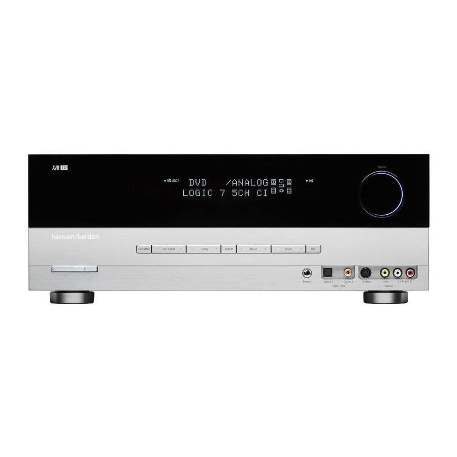
Page 5: Front Panel Controls
Front Panel Controls DIGITAL PRO LOGIC 3 STEREO 5 CH. STEREO SURR. OFF Main Power Switch System Power Control Power Indicator Headphone Jack Digital Optical 3 Input Speaker/Channel Input Indicator Surround Mode Group Selector Main Power Switch: Press this button to apply power to the AVR. - Page 6 Main Information Display: This display delivers messages and status indications to help you operate the receiver. Digital Coax 3 Input: This jack is normally used for connection to the output of portable digital audio devices, video game consoles or other products that have a coax digital jack.
-
Page 7: Rear Panel Connections
PLAY/OUT audio jacks on a VCR or other video source. AM Antenna: Connect the AM loop antenna supplied with the receiver to these terminals. If an external AM antenna is used, make connections to the AM and GND terminals in accordance with the instructions supplied with the antenna. - Page 8 Video Monitor Outputs: Connect these jacks to the composite and/or S-Video input of a TV monitor or video projector to view the output of any video source selected by the receiver’s video switcher. Front/Center Speaker Outputs: Connect these outputs to the matching + or – terminals on your front/center speakers.
-
Page 9: Remote Control Functions
Remote Control Functions Power On Button IR Transmitter Window Program Indicator Power Off Button Input Selectors AVR Selector AM/FM Tuner Select Test Button Sleep Button Surround Mode Selector Night Mode Channel Select Button Buttons Button Set Button Digital Select Numeric Keys Tuner Mode Direct Button Tuning Up/Down... - Page 10 In addition, the AVR’s remote is shipped from the factory to operate the AVR and most Harman Kardon CD or DVD play- ers and cassette decks. The remote is also capa- ble of operating a wide variety of other products using the control codes that are part of the remote.
- Page 11 VCR, DVD or satellite receiver that has a “TV/Video” func- tion, pressing this button will switch between the output of the player or receiver and the external video input to that player. Consult the Owner’s Manual for your specific player or receiver for the details of how it implements this function.
-
Page 12: Audio Equipment Connections
2. Connect the analog Play/Out jacks of a cas-... -
Page 13: Video Equipment Connections
Video 1 device. For the same reason, we recommend connecting your cable TV converter or satellite receiver to the Video 2 Audio/Video Input Jacks , and your television to the Video 3 Audio/Video... -
Page 14: Scart A/V Connections
Installation and Connections SCART A/V Connections For the connections described above your video device needs RCA (cinch) connectors or/and S- Video connectors for all Audio and Video signals: Any normal video device (Not SVHS or High 8) for only playback needs 3 RCA jacks, VCRs for record and playback even 6 RCA jacks. -
Page 15: Speaker Selection
Installation and Connections Speaker Selection No matter which type or brand of speakers is used, the same model or brand of speaker should be used at least for the front-left, center and front-right speakers. This creates a seamless front soundstage and eliminates the possibility of distracting sonic disturbances that occur when a sound moves across mismatched front-channel speakers. -
Page 16: System Configuration
System Configuration Once the speakers have been placed in the room and connected, the remaining steps are to program the system configuration memories. With the AVR two kind of memories are used, those associated individually with the input selected, e.g. surround modes, and others work- ing independently from any input selected like speaker output levels, or delay times used by the surround sound processor. - Page 17 When NONE is selected, no signal will be sent to the center channel output. The receiver will operate in a “phantom” center channel mode and center channel information will be sent to...
-
Page 18: Stereo-Direct (Bypass) Mode
System Configuration After the surround mode setting has been made with the current input, repeat the setting with all inputs you will use. The surround mode can also be changed at any time later, and the AVR’s memory system will keep the settings for the input selected, until they are changed again. -
Page 19: Output Level Adjustment
Output level adjustment is a key part of the -con- figuration process for any surround sound prod- uct. It is particularly important for a Dolby Digital receiver such as the AVR, as correct outputs will ensure that you hear sound tracks with the prop- er directionality and intensity. - Page 20 System Configuration IMPORTANT NOTE: Because this test noise will have a much lower level than normal music, the volume must be lowered after the adjustment for all channels is made, BEFORE you turn the test tone off. NOTE: This is a good time to verify that the speakers have been properly connected.
-
Page 21: Source Selection
Dolby Surround should be played in either the Dolby Pro Logic II Movie (with movies) or Music (with music) surround mode or with the Harman Kardon´s exclusive Logic 7 Movie Mode, to create a full range discrete 5.1 channel sur- round signal from surround encoded programs with a stereophonic left and right rear signal, just as it was recorded in real life (e.g. -
Page 22: Surround Mode Chart
The Pro Logic II mode creates compelling five-channel surround sound from conventional stereo recordings. Logic 7 Cinema Exclusive to Harman Kardon for AV receivers, Logic 7 is an advanced mode that extracts the Logic 7 Music maximum surround information from either surround-encoded programs or conventional stereo Logic 7 Enhance material. - Page 23 Digital bass management is not available in Surround Off mode. The...
-
Page 24: Digital Audio Playback
To create wide, enveloping sound field environments and defined pans and flyovers with all analog stereo recordings select the Dolby Pro Logic II Music mode or Harman Kardon’s exclusive Logic 7 Music mode for a dramatic improvement in comparison to the Dolby Pro Logic (I) mode of former times. -
Page 25: Surround Mode Types
You may also see the message when a satellite receiver, cable set-top or HDTV tuner is in use if the digital audio is temporarily interrupt- ed when channels are changed or when a cable box switches from a channel with a digital data stream to a channel with analog audio only. -
Page 26: Night Mode
Operation These indicators are the L/C/R/SL/SR/LFE letters that are inside the center boxes of the Speaker/Channel Input Indicators in the front panel . When a standard analog stereo or matrix surround signal is in use, only the “L” and “R” indicators will light, as analog signals have only left and right channels, respectively, even surround recordings, carry surround infor- mation on the left and right channels only. -
Page 27: Channel Direct Input
Operation Press the Set button when the name of the desired channel appears in the Main Information Display and on-screen display, and follow the instructions shown above to adjust the level. Repeat the procedure as needed until all chan- nels requiring adjustment have been set. When all adjustments have been made press the Set button twice, the AVR will return to normal... -
Page 28: Rds Operation
Operation RDS Operation The AVR is equipped with RDS (Radio Data System), which brings a wide range of informa- tion to FM radio. Now in use in many countries, RDS is a system for transmitting station call signs or network information, a description of station program type, text messages about the station or specifics of a musical selection, and the correct time. -
Page 29: Programming The Remote
As shipped from the factory, the remote is fully programmed for all AVR functions, as well as those of most Harman Kardon CD recorders, DVD play- ers, CD players and cassette decks. In addition, by following one of the methods below, you may pro- gram the remote to operate a wide range of devices from other manufacturers. -
Page 30: Macro Programming
Programming the Remote 1. Press and hold both the Input Selector for the device you wish to find the code for and the Mute button at the same time. Note that the Program/SPL Indicator will initally turn amber and begin flashing. Release the buttons and begin the next step within 20 seconds. -
Page 31: Resetting The Remote Memory
The AVR’s remote may be programmed to operate so that the channel control function for either the VCR, TV, cable or satellite receiver used in your system may be used in conjunction with one of the other devices controlled by the remote. For... - Page 32 Function List 32 FUNCTION LIST Button Name AVR Function Power On Power On Power Off Power Off Mute Mute AVR Select DVD Input Select CD Input Select Tape Tape Input Select VID 1 Video 1 Select VID 2 Video 2 Select VID 3 Video 3 Select AM/FM...
- Page 33 Function List Button Name Tape Power On Power On Power Off Power Off Mute Tape Tape Select VID 1 VID 2 VID 3 AM/FM 6 CH Input Select Sleep Test Volume Up Surround Select Night Spare Volume Down Channel/Guide Speaker/Menu Digital/Exit Delay/Prev.
-
Page 34: Troubleshooting Guide
27 so that the display is set to VFD FULL • Check speaker-wire connections for shorts at receiver and speaker ends • Contact your local Harman Kardon service depot • Select a mode other than Stereo • Check speaker mode •... -
Page 35: Technical Specifications
Depth measurement includes knobs, buttons and terminal connections. Height measurement includes feet and chassis. All features and specifications are subject to change without notice. Harman Kardon is a registered trademark. *Manufactured under license from Dolby Laboratories. “Dolby”, “Pro Logic”, and the Double-D symbol are trademarks of Dolby Laboratories, Inc. - Page 36 250 Crossways Park Drive, Woodbury, New York 11797 www.harmankardon.com Harman Consumer Group International: 2, route de Tours, 72500 Château-du-Loir, France © 2006 Harman Kardon, Incorporated Part No.: CQX1A1154Z...