Table of Contents
Advertisement
Quick Links
DMX Interface - PWINF DIN NFP
OVERVIEW
The Network Fade Processor (PWINF DIN NFP) is a DIN-rail
mounted interface that serves as an DMX/Network DMX fade
processor.
The Network Fade Processor receives ASCII text based com-
mands and process those commands to fade DMX channels
over specified times. The NFP accepts plainly readable com-
mands made up of 8-Bit ASCII characters over a standard
UDP transport.
The NFP calculates and processes fades independently, re-
ducing computation load on controllers, or enabling fade
initiation by PLC's or other non-real-time control devices.
Regardless of the number of fades running on the unit, DMX
and Network DMX refresh rates are maintained.
CONNECTIONS
The PWINF DIN NFP features terminal strips that can be removed
from the card to facilitate easy wiring installation or replacement.
Make the following connections, WITH THE POWER TURNED OFF.
POWER
The PWINF DIN NFP is designed to run on either Power-over-Ether-
net (PoE), or on an auxiliary power supply providing between 18 and
48 volts DC. The device is Class 1 PoE and will draw up to 4 Watts.
If an auxiliary supply is used, observe the correct polarity when con-
necting V+ and V-. A second set of terminals are provided so power
may be daisy-chained to other cards. The earth ground terminal
must be connected to the enclosure's chassis or electrical ground
terminal to improve EMC compliance.
DMX512
DMX connections consist of a shield and data pair. Connect DATA+
and DATA- to D1+ and D1-. Observe the same polarity convention
throughout the system. Connect the cable shield or common to the
SHLD COM terminal.
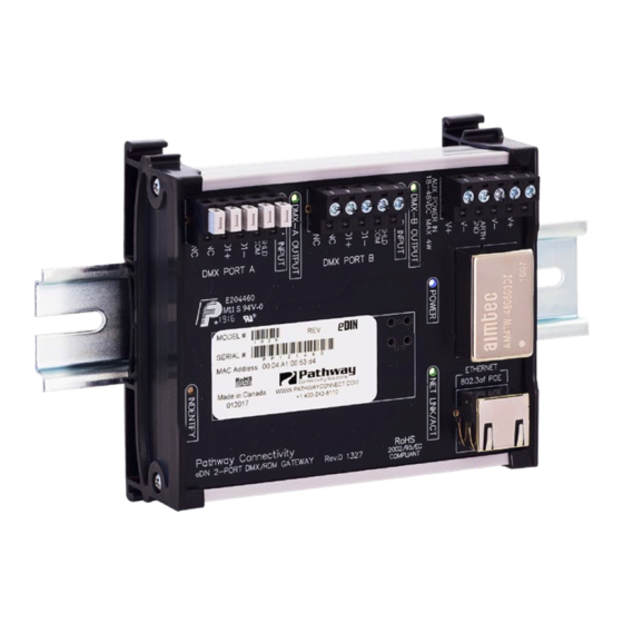
Network Fade Processor
DMX512 Outputs (2)
LED Output
Active Indicators
DMX PORT A
DMX PORT B
Female RJ45
Ethernet Connector
4.5"
[113mm]
NETWORK
All network wiring should follow standard Ethernet rules and be in-
stalled by a qualified person. As part of the installation, all wiring
should be certified under the TIA/EIA-568 standard.
STATUS INDICATORS
POWER
Blue. Steady glow indicates power supply is
OK. Off indicates no power.
IDENTIFY
Blue. Blinks when identify is active.
DMX OUTPUT
Green. Steady glow indicates port is transmit-
A/B
ting DMX. Blinking indicates no DMX output. Off
indicates Port is Disabled.
NETWORK
Green. Flickering glow means active Ethernet
LINK/ACT
network link. Off indicates no network link.
POWER IN (If PoE not in use):
18-48VDC, 4W Supply required.
Use PWPWR DIN TERM [xxxx]
Connect Earth ground to improve
EMC compliance
DIN rail release lever
Use large flat-head
screwdriver or similar tool to
gently pry lever away from
DIN rail to release
4.0"
[103mm]
Manual
Fastening mechanism
designed for 35 x 7.5mm
DIN rail
1.9"
[49mm]
03/09/22
Advertisement
Table of Contents

Summary of Contents for Pathway connectivity solutions PWINF DIN NFP
- Page 1 All network wiring should follow standard Ethernet rules and be in- stalled by a qualified person. As part of the installation, all wiring The PWINF DIN NFP features terminal strips that can be removed should be certified under the TIA/EIA-568 standard.
- Page 2 • an optional Time, • and a Terminator. The PWINF DIN NFP ships as a DMX output gateway with E1.31 The Port Letter can be “A” or “B” - matching the port designator sACN selected as the transmit network protocol.
- Page 3 DMX Interface - PWINF DIN NFP Manual Network Fade Processor COMMAND SYNTAX (cont’d) PORT RELEASE A Time is: If necessary, it is also possible to “release” all control on a port. This will stop all DMX and network communication for that port, and will •...
Need help?
Do you have a question about the PWINF DIN NFP and is the answer not in the manual?
Questions and answers