Table of Contents
Advertisement
Quick Links
Advertisement
Table of Contents

Summary of Contents for Nayar Systems Switch
- Page 1 Switch 1 — Last update: Jul 18, 2022 Nayar Systems Copyright © 2022 Nayar Systems...
-
Page 2: Table Of Contents
2.3. Device rear panel ........................6 3. Installation and start-up ........................7 3.1. Nayar Switch installation at the machine room ................8 3.2. Nayar Switch installation at the lift car ..................11 3.3. Configuration of bus termination resistors ................13 4. -
Page 3: Manufacturer Note
The device must be manipulated only by qualified and skilled professionals with specific technical knowledge to avoid a failure of the device due to inappropriate manipulation. Nayar Systems S.L. is not responsible for damage as a result of ignoring the indications and recommendations included in this manual. -
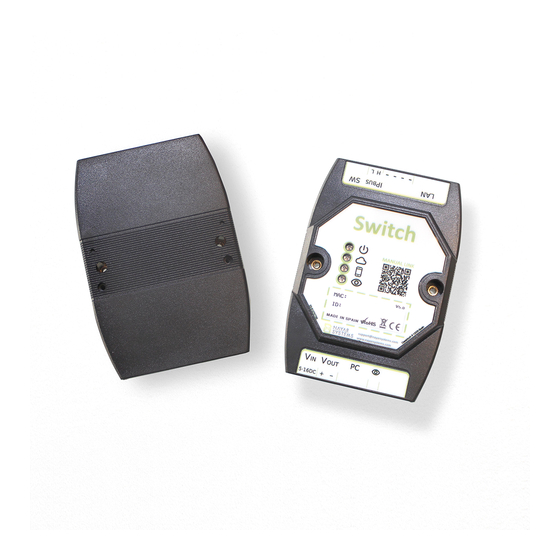
Page 4: Device Description
Switch - 1_en 2. Device description Nayar Switch is a device whose main function consists of the transmission of data from IP frames either through an interface of two standard copper cables or wireless. Therefore, Nayar Switch is the perfect mechanism to guarantee IP connectivity everywhere at lift cars. - Page 5 Nayar Systems Switch - 1_en (*) For product versions v5.0 and older, the operating range is 5 – 16 VDC. Page 3 of 19...
-
Page 6: Status Indicator Leds
Nayar Systems Switch - 1_en 2.1. Status indicator LEDs Nayar Switch has 4 LEDs for showing its status to the user: – Power LED It shows whether the device is powered ON or OFF. • Device powered OFF – • Device powered ON –... -
Page 7: Device Front Panel
Discover Button This button is configured to complete two actions: • Nayar Switch’s identification on app: A single press on this button helps identify in the app the device among all the other available products. • Link to Wi-Fi network created by Nayar Switch: A single press on this button allows a different Nayar Systems’... -
Page 8: Device Rear Panel
RJ45 connector to receive or supply data transmission throughout an ethernet cable. IPBus Nayar Switch is able to transmit IP frames through an IPBUS interface. The device includes a pluggable connector for that purpose, which has to be connected according to the positions indicated hereinafter:... -
Page 9: Installation And Start-Up
3. Installation and start-up Normally, it is required to have one Nayar Switch more than the total number of lift cars in the installation. As an example, at an installation with a single lift car, two Nayar Switches are necessary; at an installation with two lift cars, three Nayar Switch are required. -
Page 10: Nayar Switch Installation At The Machine Room
2. Connect the RJ45 cable from the LAN connector of the GSR to the LAN connector of the Nayar Switch. 3. Connect two unused wires of the travelling cable to the IPBus connector of the Nayar Switch. Page 8 of 19... - Page 11 4. Connect the power supply cables to the VIN connector by means of the DC power connector. The polarity of the DC connector must be respected. (In order to supply power to the Nayar Switch, GSR 12V output may be used). 5. Check whether the power and Internet connectivity LEDs are lit up.
- Page 12 Nayar Systems Switch - 1_en Page 10 of 19...
-
Page 13: Nayar Switch Installation At The Lift Car
3.2. Nayar Switch installation at the lift car 1. Place the device at the lift car, so as to be accessible to all the connectors of the Nayar Switch by the installer. The device must not be able to be manipulated by the elevator user. - Page 14 Switch - 1_en 4. If it is desired to use the Nayar Switch in order to feed an electronic device, VOUT connector must be used. The polarity of the DC connector must be respected. It is highly recommended to use it to feed Advertisim devices.
-
Page 15: Configuration Of Bus Termination Resistors
Nayar Systems Switch - 1_en 3.3. Configuration of bus termination resistors Depending on the installation, a specific configuration of bus termination resistors has to be applied. Bus terminating resistors are configured by using the microswitch 2 at the device rear panel. - Page 16 Nayar Systems Switch - 1_en Switch B ON Installation with two lift cars Installation schematic Configuration of bus termination resistors Microswitch 2 position Switch A Switch B1 ON Switch B2 ON Installation with three or more lift cars Installation schematic...
- Page 17 Switch B2 OFF Switch Bn ON Where Bn corresponds to the Nayar Switch placed at the last lift car of the installation (it is not recommended to connect more than 8 lift cars). Therefore, the Nayar Switch whose microswitch 2 must be at ON position are those corresponding to the first and last lift car.
- Page 18 In case of an installation with three or more lift cars, the following star-wired installation schematic must NOT be reproduced. When installation and start-up is completed correctly, all lift car Nayar Switch power and Internet connectivity LEDs should be lit up.
- Page 19 Nayar Systems Switch - 1_en Page 17 of 19...
-
Page 20: Technical Support
Nayar Systems Switch - 1_en 4. Technical support In case of any incident with your Nayar Switch device when needed technical support, please contact Nayar Systems after-sales services: (+34) 964 06 69 95 / info@nayarsystems.com. Page 18 of 19... -
Page 21: Troubleshooting
Substitute RJ45 cable Verify that the configuration of Internet connectivity LED is not Microswitch configuration is bus termination resistors at 3.3.- lit up (Lift car Nayar Switch) incorrect Configuration of bus termination resistors Check IPBUS wiring from installation schematic shown at IPBUS wiring is incorrect 3.3.- Configuration of bus...
Need help?
Do you have a question about the Switch and is the answer not in the manual?
Questions and answers