Table of Contents
Advertisement
Available languages
Available languages
Quick Links
CUSTOMER SERVICE
SERVICIO AL CLIENTE
USA: 1-877-617-3501
Mexico: 01 800 843 1111
www.powerstroketools.com
NEUTRAL FLOATING
NEUTRAL DE FLOTACIÓN
Do not use E15 or E85 fuel (or fuel containing greater than 10% ethanol) in this product. It is a
violation of federal law and will damage the unit and void your warranty.
No utilice combustibles E15 o E85 (ni combustibles que contengan más de 10 % de etanol) con
este producto. Esto constituye una violación a la ley federal, dañará la unidad y anulará la garantía.
TABLE OF CONTENTS
Important Safety Instructions ...............................................3-4
Specific Safety Rules .............................................................. 4
Symbols ...............................................................................5-7
Electrical ..............................................................................8-9
Features ...........................................................................10-11
Assembly .............................................................................. 11
Operation .........................................................................12-14
Maintenance ....................................................................15-17
Accessories ........................................................................... 18
Troubleshooting .................................................................... 18
Warranty ...........................................................................19-21
Parts Ordering / Service ...........................................Back Page
WARNING:
To reduce the risk of injury, the user must
read and understand the operator's manual before using this
product.
SAVE THIS MANUAL FOR
FUTURE REFERENCE
OPERATOR'S MANUAL
DIGITAL INVERTER GENERATOR
NOTICE
AVISO
Instrucciones de seguridad importantes .............................. 3-4
Reglas de seguridad específicas .............................................4
Símbolos .............................................................................. 5-7
Aspectos eléctricos .............................................................. 8-9
Características ................................................................. 10-11
Armado ...................................................................................11
Funcionamiento ................................................................ 12-15
Mantenimiento .................................................................. 15-18
Accessorios ............................................................................18
Corrección de problemas ...........................................................
Garantía ............................................................................ 20-22
Pedidos de piezas / servicio ...............................Pág. posterior
usuario debe leer y comprender el manual del operador antes
de usar este producto.
MANUAL DEL OPERADOR
GENERADOR DEL INVERSOR
ÍNDICE DE CONTENIDO
Para reducir el riesgo de lesiones, el
GUARDE ESTE MANUAL
PARA FUTURAS CONSULTAS
DE DIGITACES
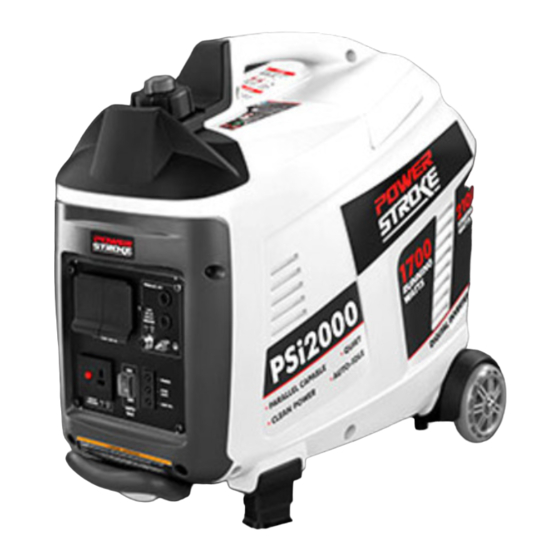
PSi2000B
Series / Serie
Advertisement
Table of Contents

Related Manuals for PowerStroke PSi2000B Series


Summary of Contents for PowerStroke PSi2000B Series
-
Page 1: Table Of Contents
OPERATOR’S MANUAL MANUAL DEL OPERADOR DIGITAL INVERTER GENERATOR GENERADOR DEL INVERSOR DE DIGITACES PSi2000B Series / Serie CUSTOMER SERVICE SERVICIO AL CLIENTE USA: 1-877-617-3501 Mexico: 01 800 843 1111 www.powerstroketools.com NEUTRAL FLOATING NEUTRAL DE FLOTACIÓN NOTICE AVISO Do not use E15 or E85 fuel (or fuel containing greater than 10% ethanol) in this product. It is a violation of federal law and will damage the unit and void your warranty. - Page 2 See this fold-out section for all of the figures referenced in the operator’s manual. Consulte esta sección desplegable para ver todas las figuras a las que se hace referencia en el manual del operador.
- Page 3 Fig. 1 H - Retractable handle (mango retráctil) O - Auto idle switch (interruptor de ralentí A - On/off switch (interruptor de encendido y I - Battery charging cable (cable para cargar la automático) apagado) batería) P - Spark plug cover (cubierta de la bujía) B - Engine maintenance cover (cubierta de mantenimiento del motor) J - DC circuit breaker (disyuntor de circuito de...
- Page 4 Fig. 5 Fig. 10 Fig. 7 A - Starter grip and rope (mango del arrancador y cuerda) Fig. 8 A - On/off switch (interruptor de encendido y apagado) Fig. 11 B - Off (apagado) C - On (encendido) Fig. 6 A - On (encendido) B - Auto idle switch (interruptor de ralentí...
- Page 5 Fig. 13 Fig. 15 Fig. 17 A - Carburetor drain screw (tornillo de drenaje A - Screws (tornillos) del caburador) B - Muffler outlet (recubrimiento del silenciador) A - Oil cap/dipstick (tapa de relleno de aceite/ C - Spark arrestor (parachispas) Fig.
- Page 6 To register your PowerStroke product, please visit: www.powerstroketools.com LOCATE GENERATOR AT LEAST 20 FT.* AWAY TO REDUCE THE RISK OF CARBON MONOXIDE GETTING INSIDE THE HOME * Minimum distance as recommended by U.S. Department of Health and Human Services Centers for Disease Control and Prevention (www.cdc.gov/co). Your specific home and/or wind conditions may require additional distance.
-
Page 7: Important Safety Instructions
IMPORTANT SAFETY INSTRUCTIONS Do not allow children or untrained individuals to use this unit. DANGER: Do not operate the engine in a confined space where Carbon Monoxide. Using a generator indoors CAN KILL dangerous carbon monoxide fumes can collect. Carbon YOU IN MINUTES. -
Page 8: Specific Safety Rules
IMPORTANT SAFETY INSTRUCTIONS Use only authorized replacement parts and accessories Maintain the unit per maintenance instructions in this and follow instructions in the Maintenance section of this Operator’s Manual. manual. Use of unauthorized parts or failure to follow Inspect the unit before each use for loose fasteners, fuel maintenance instructions may create a risk of shock or leaks, etc. -
Page 9: Symbols
SYMBOLS The following signal words and meanings are intended to explain the levels of risk associated with this product. SYMBOL SIGNAL MEANING Indicates an imminently hazardous situation, which, if not avoided, will result DANGER: in death or serious injury. Indicates a potentially hazardous situation, which, if not avoided, could result WARNING: in death or serious injury. - Page 10 SYMBOLS Some of the following symbols may be used on this product. Please study them and learn their meaning. Proper interpretation of these symbols will allow you to operate the product better and safer. SYMBOL NAME DESIGNATION/EXPLANATION Volts Voltage Amperes Current Hertz Frequency (cycles per second)
- Page 11 SYMBOLS ENGINE LUBRICANT WARNING You must add lubricant before first operating the generator. The oil reservoir capacity is 13.52 oz. Always check the lubricant level before each operation. The lubricant level should always register between the hatched areas on the dipstick. The unit is equipped with a sensor which will automatically shut off the engine if the lubricant level falls below a safe limit.
-
Page 12: Electrical
ELECTRICAL EXTENSION CORD CABLE SIZE Refer to the table below to ensure the cable size of the extension cords you use are capable of carrying the required load. Inadequate size cables can cause a voltage drop, which can damage the appliance and overheat the cord. Load in Watts Maximum Allowable Cord Length Current in... - Page 13 ELECTRICAL GENERATOR CAPACITY Never add more loads than the generator capacity. Take special care to consider surge loads in generator capacity Make sure the generator can supply enough continuous (run- as previously described. ning) and surge (starting) watts for the items you will power at the same time.
-
Page 14: Features
FEATURES PRODUCT SPECIFICATIONS ENGINE GENERATOR Engine Type ......Single Overhead Cam (SOHC) Rated Voltage .........120 V AC/12 V DC Spark Plug ..........NHSP LD A7RTC Rated Amps ..........14.2 A AC/7.5 A DC Rated Running Watts ..........1,700 W Cooling System ...........Forced Air Starting Watts ............ -
Page 15: Assembly
FEATURES RESET BUTTON STARTER GRIP AND ROPE The reset button is used to restore power if an overload The starter grip and rope is used (along with the on/off switch) occurs. To restore power, depress the reset button. to start the generator’s engine. RETRACTABLE HANDLE The generator is equipped with a retractable handle that can be adjusted for storage and transportation. -
Page 16: Operation
OPERATION NOTICE: DANGER: Before each use, inspect the entire product for damaged, Carbon Monoxide. Using a generator indoors CAN KILL missing, or loose parts such as screws, nuts, bolts, caps, YOU IN MINUTES. etc. Tighten securely all fasteners and caps and do not Generator exhaust contains high levels of carbon operate this product until all missing or damaged parts monoxide (CO), a poisonous gas you cannot see or smell. - Page 17 OPERATION CHECKING/ADDING LUBRICANT Fuel system damage or performance problems resulting from the use of an oxygenated fuel containing more than See Figure 3. the percentages of oxygenates stated previously are not NOTICE: covered under warranty. Attempting to start the engine before it has been properly Ethanol.
- Page 18 OPERATION Put the auto idle switch in the OFF (O) position. NOTE: To prevent short circuit, keep away from a metal surface during clamp connection. Pull the starter grip and rope until the engine runs (a maximum of 6 times). ...
-
Page 19: Maintenance
MAINTENANCE CHECKING/CLEANING AIR FILTER WARNING: See Figures 11 - 12. When servicing, use only identical replacement parts. For proper performance and long life, keep air filter clean. Use of any other parts could create a hazard or cause Loosen the screw at the top of the engine cover. Remove product damage. - Page 20 MAINTENANCE Measure plug gap. The correct gap is 0.024−0.028 in. DRAINING FUEL TANK/CARBURETOR (0.60-0.70 mm). To widen gap, if necessary, carefully See Figures 16 - 17. bend the ground (top) electrode. To lessen gap, gently To help prevent gum deposits in the fuel system, drain the tap ground electrode on a hard surface.
- Page 21 MAINTENANCE STORAGE When preparing the generator for storage, allow the unit to cool completely then follow the guidelines below. STORAGE TIME PRIOR TO STORING Less than 2 months Drain gasoline from tank and dispose of in a suitable container according to state and local ordinances. 2 months to 1 year Drain fuel from carburetor.
-
Page 22: Accessories
ACCESSORIES The following recommended accessory is available and for use on this unit only: AUN9230PK Positive parallel kit terminal WARNING: Current attachments and accessories available for use with this tool are listed above. Do not use any attachments or accessories not recommended by the manufacturer of this tool. -
Page 23: Warranty
LIMITED WARRANTY WARRANTY COVERAGE OWT Industries, Inc., (the Company) warrants to the original retail purchaser that this PowerStroke Product is free from defects in material and workmanship and agrees to repair or replace, at the Company’s sole discretion, any defective Product free of charge within these time periods from the date of purchase: Two years, if the Product is used solely for personal, family, or household use;... - Page 24 WARRANTY LIMITED ENGINE WARRANTY OWT Industries, Inc., (the Company), warrants that each 4. Broken or scored parts caused by low oil level, dirty, new engine sold by it will be free, under normal use and or improper grade of oil. service, from defects in material and workmanship for a 5.
- Page 25 WARRANTY CALIFORNIA EMISSIONS CONTROL WARRANTY STATEMENT YOUR WARRANTY RIGHTS AND OBLIGATIONS (4) Repair or replacement of any warranted part under the warranty provisions herein must be performed at a warranty station at no The California Air Resources Board, United Sates Environmental Protection charge to the owner.
- Page 26 Para registrar su producto de PowerStroke, por favor visita: www.powerstroketools.com UBIQUE EL GENERADOR A UNA DISTANCIA DE POR LO MENOS 6 M (20 PIES)* PARA REDUCIR EL RIESGO DE QUE EL MONÓXIDO DE CARBONO INGRESE EN LA CASA Distancia mínima recomendada por el Departamento de Salud y Servicios Humanos y por los Centros para el Control y la Prevención de Enfermedades de los Estados Unidos (www.cdc.gov/co).
-
Page 27: Instrucciones De Seguridad Importantes
INSTRUCCIONES DE SEGURIDAD IMPORTANTES No haga funcionar el motor en un espacio confinado donde se puedan recolectar las emanaciones de monóxido de PELIGRO: carbono. El monóxido de carbono, un gas incoloro, inodoro y sumamente peligroso, puede causar la pérdida de la Monóxido de carbono. -
Page 28: Reglas De Seguridad Específicas
INSTRUCCIONES DE SEGURIDAD IMPORTANTES portátiles que están conectados correctamente pueden incumplimiento de las instrucciones de mantenimiento puede sobrecargarse. De esta manera, los componentes del significar un riesgo de descarga eléctrica o de lesiones. generador pueden recalentarse o exigirse demasiado, lo Mantenga la unidad según las instrucciones de mantenimiento que podría producir una falla en el generador. -
Page 29: Símbolos
SÍMBOLOS Las siguientes palabras de señalización y sus significados tienen el objeto de explicar los niveles de riesgo relacionados con este producto. SÍMBOLO SEÑAL SIGNIFICADO Indica una situación peligrosa inminente, la cual, si no se evita, causará PELIGRO: la muerte o lesiones serias. Indica una situación peligrosa posible, la cual, si no se evita, podría causar ADVERTENCIA: la muerte o lesiones serias. - Page 30 SÍMBOLOS Es posible que se empleen en este producto algunos de los siguientes símbolos. Le suplicamos estudiarlos y aprender su significado. Una correcta interpretación de estos símbolos le permitirá utilizar mejor y de manera más segura el producto. SÍMBOLO NOMBRE DENOMINACIÓN / EXPLICACIÓN Voltios Voltaje...
- Page 31 SÍMBOLOS ADVERTENCIA DEL LUBRICANTE DE MOTOR Antes de utilizar el generador debe abastecerlo de lubricante. El tanque de aceite tiene una capacidad de 420.5 ml (13.52 onzas.). Antes de utilizar la unidad, revise el nivel de lubricante. El nivel de lubricante siempre debe estar entre las áreas cubierta con rayas entrecruzadas de la varilla de nivel.
-
Page 32: Aspectos Eléctricos
ASPECTOS ELÉCTRICOS CALIBRE DEL CORDÓN DE EXTENSIÓN Consulte el cuadro mostrado abajo para asegurarse de que el calibre de los cordones de extensión que utilice puedan con la carga eléctrica requerida. Los cordones de calibre insuficiente pueden causar una caída de voltaje, lo cual puede quemar el dispositivo y recalentar el cordón mismo. - Page 33 ASPECTOS ELÉCTRICOS CAPACIDAD DEL GENERADOR 2. Enchufe y active la primera carga, preferiblemente la máxima carga que tenga. Cerciórese que el generador pueda suministrar suficientes 3. Deje que se estabilice la salida del generador (el motor vatios de potencia continua (en marcha) y de sobrecorriente marcha uniformemente y el dispositivo acoplado funciona (al arrancar) para los equipos que desee alimentar al mismo correctamente).
-
Page 34: Características
CARACTERÍSTICAS ESPECIFICACIONES DEL PRODUCTO GENERADOR MOTOR Voltaje nominal ........120 V C.A/12 V C.C. Tipo de motor ......Leva única elevada (SOHC) Amperaje nominal......14,2 A C.A/7,5 A C.C. Bujía............NHSP LD A7RTC Potencia en marcha ..........1 700 W Sistema de enfriamiento........Aire forzado Potencia de arranque .......... -
Page 35: Armado
CARACTERÍSTICAS TERMINALES DE JUEGO PARALELOR MANGO RETRÁCTIL Las terminales de juego paralelor son utilizadas con un juego El generador está equipado con un mango retráctil que puede paralelor (vendió separadamente) que permitirá generadores ajustarse para el almacenamiento y el transporte. para ser unidos para aumentar salida. -
Page 36: Funcionamiento
FUNCIONAMIENTO AVISO: PELIGRO: El parachispas que acompaña a este producto no ha sido Monóxido de carbono. Usar un generador en el interior evaluado por el Servicio Forestal del Departamento de LO MATARÁ EN POCOS MINUTOS. Agricultura de EE. UU. y no se puede usar en terrenos Los gases de escape del generador contienen niveles forestales de EE. - Page 37 FUNCIONAMIENTO USO DE ESTABILILZADOR DE COMBUSTIBLE NOTA: El generador está sobrecargado, la luz del indicador de potencia se apagará. El combustible se hace viejo, se oxida y descompone al Sobrecarga: paso del tiempo. Agregando estabilizador de combustible El indicador de sobrecarga se encenderá si se supera la (no incluido) se prolonga la vida útil del combustible y se capacidad de amperaje y vataje del generador.
- Page 38 FUNCIONAMIENTO APAGADO DEL MOTOR Si está caliente el motor, permita que se enfríe la generador durante cinco minutos antes de reabastecerla de gasolina. Vea la figura 5. SIEMPRE llene el tanque al aire libre y teniendo apagada Desconecte del generador toda carga presente. la máquina.
-
Page 39: Mantenimiento
FUNCIONAMIENTO TRASLADO EL GENERADOR Arrancar la unidad. Vea la figura 10. NOTE: Los receptáculos de CA pueden usarse mientras el receptáculo de CC se está usando. Apague la generador. El paquete de baterías se siente un poco caliente al ... - Page 40 MANTENIMIENTO Retire el tornillo que está en el centro de la tapa del filtro de Inspeccione la bujía para ver si está dañada, y límpiela con un aire. Retire la tapa del filtro de aire y hágala a un lado. cepillo de alambre antes de volver a instalarla.
- Page 41 MANTENIMIENTO DRENAJE DEL TANQUE DEL COMBUSTIBLE Coloque un recipiente adecuado bajo el tornillo de drenaje del carburador para recibir el combustible; afloje el tornillo. Y DEL CARBURADOR Permita que se drene completamente el combustible y caiga Vea las figuras 16 y 17. en el recipiente.
-
Page 42: Accessorios
MANTENIMIENTO PROGRAMA DE MANTENIMIENTO NOTA: Si recibe un manual del motor para este generador en particular, respete el cronograma de mantenimiento que se indique en el manual del motor y no la información de mantenimiento que figura a continuación. Al cabo del Cada año Cada 3 meses Cada 6 meses... -
Page 43: Corrección De Problemas
CORRECCIÓN DE PROBLEMAS PROBLEMA CAUSA POSIBLE SOLUCIÓN El motor no arranca. El interruptor del motor está en apagado Ponga el interruptor del motor en encendido (ON). (OFF). No hay combustible. Llene el tanque de combustible. Gasolina pasada o agua pasada en la Drene todo el sistema y reabastézcalo con gasolina. -
Page 44: Garantía
Para obtener el servicio de garantía: Llame sin cargo al 1-877-617-3501 o escriba a OWT Industries, Inc., P.O. Box 35, Hwy. 8, Pickens, SC 29671. Para obtener el servicio de garantía fuera de los EE. UU., comuníquese con el establecimiento PowerStroke local. Pàgina 20 — Español... - Page 45 GARANTÍA DECLARACIÓN DE GARANTÍA LIMITADA AL MOTOR OWT Industries, Inc., (la Compañía), garantiza al válvulas, el carburador u otros componentes internos). comprador minorista original que cada motor nuevo que 4 Piezas rotas o rayadas debido a un bajo nivel de se venda carecerá...
- Page 46 GARANTÍA DECLARACIÓN DE GARANTÍA DEL CONTROL DE EMISIONES DE CALIFORNIA SUS DERECHOS Y OBLIGACIONES EN RELACIÓN CON LA GARANTÍA (5) Sin perjuicio de los términos aquí expuestos, el mantenimiento o las reparaciones relacionados con la garantía serán realizados en todos La Junta de Recursos del Aire de California (CARB), la Agencia de Protección Ambiental nuestros centros de distribución que estén habilitados para realizar de los Estados Unidos (EPA) y Zhejiang ZhongJian Technology Co., Ltd.
- Page 47 NOTES / NOTAS Page / Pàgina 22...
-
Page 48: Advertencia
DIGITAL INVERTER GENERATOR GENERADOR DEL INVERSOR DE DIGITACES PSi2000B OPERATOR’S MANUAL SERIES / SERIE MANUAL DEL OPERADOR CALIFORNIA PROPOSITION 65 SERVICE WARNING: For parts or service, contact your nearest authorized service dealer. Be sure to provide all relevant information when you call or visit. For the location of the This product, its exhaust, and other authorized service dealer nearest you, please call 1-877-617-3501.
Need help?
Do you have a question about the PSi2000B Series and is the answer not in the manual?
Questions and answers