Puritan Bennett 840 Service Manual
Hide thumbs
Also See for 840:
- Operator and technical reference manual (21 pages) ,
- Service manual (658 pages)

Related Manuals for Puritan Bennett 840


Summary of Contents for Puritan Bennett 840
- Page 1 Service Manual V e n t i l a t o r S y s t e m 4-070496-00 Rev C June, 2005 4-070496-00 Rev. C (06/05)
- Page 3 Nothing in this manual shall limit or restrict in any way Puritan Bennett’s right to revise or otherwise change or modify the equipment (including its software) described herein, without notice. In the absence of an express, written agreement to the contrary, Puritan Bennett has no obligation to furnish any such revisions, changes, or modifications to the owner or user of the equipment (including its software) described herein.
- Page 4 In case of fire or a burning smell, immediately disconnect the ventilator from the oxygen supply, facility power, and BPS. • When handling any part of the 840 Ventilator System, always follow your hospital infection control guidelines for handling infectious material.
- Page 5 • An alternative source of ventilation should always be available when using the 840 Ventilator System. • The 840 Ventilator System is a member of the 800 Series™ family of products. Any accessory whose model number is 80x (for example, the 802 Backup Power Source or 806 Compressor Unit) operates with all 800 Series ventilators.
- Page 6 Preface Electromagnetic susceptibility The 840 Ventilator System complies with the requirements of IEC 601-1-2 (EMC Collateral Standard), including the E-field susceptibility requirements at a level of 10 volts per meter, at frequencies from 26 MHz to 1 GHz, and the ESD requirements of this standard. However, even at this level of device immunity, certain transmitting devices (cellular phones, walkie-talkies, cordless phones, paging transmitters, etc.) emit radio frequencies that could interrupt...
-
Page 7: Table Of Contents
2.3.3 Exhalation module..................... 2-33 2.3.3.1 Exhalation module components .............. 2-34 2.3.3.2 Exhalation module operation..............2-35 2.3.4 806 Compressor Unit ..................2-38 2.3.4.1 806 Compressor unit components............2-38 2.3.4.2 806 Compressor unit operation ............... 2-41 840 Ventilator System Service Manual 4-070496-00 Rev. C (06/05) - Page 8 2.6.3 Pressure transducer autozero................2-98 2.6.4 Power monitoring and power fail handling ............. 2-100 2.6.4.1 Loss of power source................2-100 2.6.4.2 Supply voltage monitoring..............2-101 2.7.1 Safety valve open (SVO) state................2-101 4-070496-00 Rev. C (06/05) 840 Ventilator System Service Manual...
- Page 9 4.2.13 Exp Valve Calibration..................4-9 4.2.13.1 Running Exp Valve Calibration ..............4-9 4.2.14 Vent Inop Test ....................4-11 4.2.14.1 Running the Vent Inop Test ..............4-11 4.2.14.2 Flow Sensor Calibration ................4-12 840 Ventilator System Service Manual 4-070496-00 Rev. C (06/05)
- Page 10 5.7.4 Regulator setting verification................5-9 5.7.5 Serial loopback test (10.4-inch GUI only) ............5-10 5.7.6 Performance verification using PTS 2000 Performance Test System and BreathLab 840 VTS software............... 5-10 5.7.7 Manual ventilator check using equipment other than PTS 2000 Performance Test System .................. 5-10 5.8 Regulator calibration hose repair instructions ............
- Page 11 8.14.2 9.4-inch GUI window ..................8-22 8.14.3 Installing the 9.4-inch bezel................8-23 8.14.4 The 9.4-inch keyboard assembly..............8-23 8.14.4.1 Removing 9.4-inch keyboard assembly ............ 8-23 8.14.4.2 Installing the 9.4-inch keyboard assembly..........8-25 840 Ventilator System Service Manual 4-070496-00 Rev. C (06/05)
- Page 12 8.15.7 Humidifier receptacle (100 – 120 V models only) ..........8-52 8.15.7.1 Removing humidifier receptacle .............. 8-52 8.15.7.2 Installing humidifier receptacle..............8-52 8.15.7.3 AC panel ....................8-53 8.15.8 Inspiratory module..................8-54 4-070496-00 Rev. C (06/05) 840 Ventilator System Service Manual...
- Page 13 8.15.11.6AC power supply blindmate harness............8-95 8.15.12 Release handle....................8-97 8.15.12.1Removing release handle ................. 8-97 8.15.12.2Installing release handle ................8-97 8.16 806 compressor unit ....................8-97 8.17 Servicing the 806 compressor.................. 8-98 840 Ventilator System Service Manual 4-070496-00 Rev. C (06/05)
- Page 14 8.18.4 BPS PCB ......................8-116 8.18.4.1 Removing BPS PCB................8-116 8.18.4.2 Installing BPS PCB ................. 8-116 8.19 Cart ........................8-116 8.19.1 Casters......................8-116 8.19.1.1 Removing casters .................. 8-116 8.19.1.2 Installing casters..................8-117 4-070496-00 Rev. C (06/05) 840 Ventilator System Service Manual...
- Page 15 9.1 How to use this parts list....................9-1 9.2 840 Ventilator System patient system and accessories ..........9-3 9.2.1 840 Ventilator System NeoMode patient system and accessories ......9-6 9.3 Flex arm assembly, oxygen and air hose assemblies, power cords ....... 9-8 9.3.1 Flex arm assembly ....................
- Page 16 Contents This page intentionally blank. 4-070496-00 Rev. C (06/05) 840 Ventilator System Service Manual...
- Page 17 840 Ventilator System RS-232 serial port pinout ....... . 1-6...
- Page 18 AC panel ............. 2-51 Figure 2-43. 840 Ventilator System interconnect diagram – AC panel ......2-52 Figure 2-44.
- Page 19 BDU ..............8-42 xvii 840 Ventilatory System Service Manual 4-070496-00 Rev. C (06/05)
- Page 20 Fans installed in compressor ..........8-100 xviii 4-070496-00 Rev. C (06/05) 840 Ventilatory System Service Manual...
- Page 21 Flex arm insert ............8-118 Figure 9-1. 840 Ventilator System patient system and accessories ......9-5 Figure 9-2.
- Page 22 Figures This page is intentionally blank. 4-070496-00 Rev. C (06/05) 840 Ventilatory System Service Manual...
- Page 23 Recommended separation distances between portable and mobile RF communications equipment and the 840 Ventilator System ......1-11 Table 1-7.
- Page 24 840 Ventilator diagnostic codes ........
-
Page 25: General Information
The 840 Ventilator System Service Manual is intended to be used in conjunction with the 840 Ventilator System Operator’s and Technical Reference Manual. Both manuals are needed for field repair of the ventilator. -
Page 26: Configuration Information
Remote nurse call unit: An analog output connector permits connection to a remote nurse call unit. (Puritan Bennett does not supply nurse’s call units or cables.) Refer to the 840 Ventilator System Operator’s and Technical Reference Manual for nurse call specifications. -
Page 27: Specifications
The oxygen sensor should be replaced two years after date of manufacture, or as often as necessary. Actual sensor life depends on operating environment; operation at higher temperature or O % levels will shorten sensor life. 840 Ventilator System Service Manual 4-070496-00 Rev. C (06/05) - Page 28 (that is, the humidifier or compressor connections) may increase patient leakage current to values that exceed the allowable limits. Alarm volume 45 dB(A) to 85 dB(A) Compressor sound 59 dB(A) at 1 meter distance from all sides pressure level 4-070496-00 Rev. C (06/05) 840 Ventilator System Service Manual...
-
Page 29: Figure 1-1. Remote Alarm (Nurse's Call) Port Pinout (View From Back Of Gui)
The remote alarm port is a 4-pin female connector. Allowable current is 500 mA at 30 V DC (maximum). 8-00020 Signal Normally closed (NC) Relay common Normally open (NO) Not connected Figure 1-1. Remote alarm (nurse’s call) port pinout (view from back of GUI) 840 Ventilator System Service Manual 4-070496-00 Rev. C (06/05) -
Page 30: Figure 1-2. 840 Ventilator System Rs-232 Serial Port Pinout
RS-232 (serial) port (Figure 1-2). A 9-pin male connector configured as data terminal equipment capabilities (cont) (DTE). Allowable current is 0.2 A at 10 V DC (maximum). 1 2 3 4 5 8-00019 Figure 1-2. 840 Ventilator System RS-232 serial port pinout Signal Not connected Receive data (RxD) Transmit data (TxD... -
Page 31: Compliance And Approvals
General information 1.6 Compliance and approvals The 840 Ventilator System was developed in accordance with pertinent North American and International standards (Table 1-2). The manufacturing facility for this product is certified to EN ISO 13485:2000 (ISO 13485:1996) Quality Systems - Medical Devices - Particular Requirements for the Application of ISO 9001:1994. -
Page 32: Manufacturer's Declaration
Table 1-3: Electromagnetic Emissions The 840 Ventilator System is intended for use in the electromagnetic environment specified below. The customer or the user of the 840 Ventilator System should assure that it is used in such an environment. Electromagnetic environment–... -
Page 33: Table 1-4. Electromagnetic Immunity
Table 1-4: Electromagnetic Immunity The 840 Ventilator System is intended for use in the electromagnetic environment specified below. The customer or the user of the 840 Ventilator System should assure that it is used in such an environment. IEC 60601 test Electromagnetic environment–... -
Page 34: Table 1-5. Electromagnetic Immunity-Conducted And Radiated Rf
Table 1-5: Electromagnetic immunity–conducted and radiated RF The 840 Ventilator System is intended for use in the electromagnetic environment specified below. The customer or the user of the 840 Ventilator System should assure that it is used in such an environment. -
Page 35: Table 1-6. Recommended Separation Distances Between Portable And Mobile Rf Communications Equipment And The 840 Ventilator System
FM radio broadcast and TV broadcast cannot be predicted theoretically with accuracy. To assess the electromagnetic environment due to fixed RF transmitters, an electromagnetic site survey should be considered. If the measured field strength in the location in which the 840 Ventilator System is used exceeds the applicable RF compliance level above, the 840 Ventilator System should be observed to verify normal operation. - Page 36 General information Table 1-6: Recommended separation distances between portable and mobile RF communications equipment and the 840 Ventilator System (continued) For transmitters rated at a maximum output power not listed above, the recommended separation distance d in meters (m) can be determined using the equation applicable to the frequency of the transmitter, where P is the maximum output power rating of the transmitter in watts (W) according to the transmitter manufacturer.
-
Page 37: Table 1-7. Compliant Cables
Warning The use of accessories and cables other than those specified, with the exception of parts sold by Puritan Bennett as replacements for internal components, may result in increased emissions or decreased immunity of the 840 Ventilator System. Cable or Accessory... -
Page 38: Technical Information
General information 1.7 Technical information Refer to Table 1-8 for 840 Ventilator System miscellaneous technical information. NOTE: When pressure units are set to hPa, pressure delivery and spirometry are subject to an additional 2% error. Table 1-8: Technical information Maximum limited pressure 127.5 cmH... - Page 39 Inspiratory pneumatics: 50 mL ±5 mL Expiratory pneumatics: 1000 mL ±25 mL (including expiratory filter and collector vial) The 840 Ventilator automatically adjusts for volume losses due to gas compressibility (that is, automatic compliance compensation), subject to a maximum delivered volume of 2500 mL.
-
Page 40: Range, Resolution, Accuracy, And New Patient/Default Settings
Pediatric: 15 s Adult: 20 s Apnea mandatory type Range: VC or PC Resolution: N/A Accuracy: N/A New patient: PC with NEONATAL patient circuit VC with PEDIATRIC or ADULT patient circuit 1-16 4-070496-00 Rev. C (06/05) 840 Ventilator System Service Manual... - Page 41 (7.25 x IBW); with PEDIATRIC or ADULT patient circuit Normal (non-apnea) ventilation Constant during rate change Range: Inspiratory time, I:E ratio, or expiratory time; T in BILEVEL Resolution: Not applicable Accuracy: Not applicable New patient: Inspiratory time 1-17 840 Ventilator System Service Manual 4-070496-00 Rev. C (06/05)
- Page 42 5 kg for 50 to 100 kg 10 for 100 to 150 kg Accuracy: Not applicable New patient: 3.0 kg with NEONATAL patient circuit 15 kg with PEDIATRIC patient circuit 50 kg with ADULT patient circuit 1-18 4-070496-00 Rev. C (06/05) 840 Ventilator System Service Manual...
- Page 43 Accuracy: ± (0.5 + 10% of setting) L/min of the flow command input to the flow controller, at the end of each control interval, after the first 100 milliseconds of inspiration. 1-19 840 Ventilator System Service Manual 4-070496-00 Rev. C (06/05)
- Page 44 = OFF, high exhaled tidal volume = OFF, high respiratory rate = OFF, low exhaled mandatory tidal volume = OFF, low exhaled minute volume = 0.05 L, low exhaled spontaneous tidal volume = OFF 1-20 4-070496-00 Rev. C (06/05) 840 Ventilator System Service Manual...
- Page 45 T Any combination of settings for V , f, and flow pattern that violates these boundaries is rejected. Refer to the Technical Reference section of the 840 Ventilator System Operator’s and Technical Reference Manual for more details. 1-21 840 Ventilator System Service Manual...
- Page 46 , PEEP, or that violates the above boundaries SUPP MEAN is rejected. Refer to the Technical Reference section of part of the 840 Ventilator System Operator’s and Technical Reference Manual for more details. Vent type Range: INVASIVE or NIV (non-invasive)
- Page 47 Resolution: 1 mL for 1 to 100 mL; 5 mL for 100 to 400 mL; 10 mL for 400 to 2500 mL New patient: 7.25 x IBW x 0.70 when vent type is INVASIVE; OFF when vent type is NIV 1-23 840 Ventilator System Service Manual 4-070496-00 Rev. C (06/05)
- Page 48 ± ((4 x respiratory rate) + 10% of reading) mL with NEONATAL patient circuit ± ((10 x respiratory rate)+10% of reading) mL with PEDIATRIC or ADULT patient circuit = time to exhale 90% of exhaled volume 1-24 4-070496-00 Rev. C (06/05) 840 Ventilator System Service Manual...
- Page 49 O/L/s for 10 to 500 cmH O/L/s Accuracy: ± (3 + 20%) of actual value cmH O/L/s (does not apply if C < 5 mL/cmH STAT or V < 20 L/min 1-25 840 Ventilator System Service Manual 4-070496-00 Rev. C (06/05)
- Page 50 1 cmH O for 10 to 130 cmH Total respiratory rate (f Range: 0 to 200/min Resolution: 0.1/min for 0.0 to 9.9/min; 1/min for 10 to 200/min Accuracy: ± 0.8/min 1-26 4-070496-00 Rev. C (06/05) 840 Ventilator System Service Manual...
-
Page 51: Tools, Equipment, And Service Materials
General information 1.9 Tools, equipment, and service materials The tools, equipment, and service materials listed in Table 1-10 are used to service the 840 Ventilator System. Refer to Section 5 for a list of required tools, equipment, and service materials specific to performance verification. - Page 52 (2 required) Grease, Krytox 4-732130-00 Lubricating O-rings Hose, regulator calibration 4-079050-00 (quick disconnect) Performance verification 4-079051-00 (female) Isopropyl alcohol Local supplier General cleaning Leak detector fluid 4-004489-00 Leak-testing 1-28 4-070496-00 Rev. C (06/05) 840 Ventilator System Service Manual...
- Page 53 40 ° C; measurement accuracy: ±0.75 of reading; response: ≤ 100 Software download device 4-075497-00 BDU and GUI software updates (For use by Puritan Bennett Customer Service Engineers, only) Static-dissipative field service kit 4-018149-00 Various service procedures (includes wrist strap, static dissipative mat, and earth (ground) cord) Stoppers, no.
-
Page 54: Periodic Maintenance
Table 1-11 lists the periodic maintenance activities required for the 840 Ventilator System. See the Ventilator Information screen for total hours of operation for the ventilator and compressor. -
Page 55: Table 1-11. Schedule Of Periodic Maintenance
Use appropriate preventive maintenance kit (see Table 1-12). Every 15,000 hours NOTE: If any part found in a preventive maintenance kit requires replacement before the recommended interval elapses, consider installing the entire kit anyway. 1-31 840 Ventilator System Service Manual 4-070496-00 Rev. C (06/05) -
Page 56: Service Kits
General information 1.11 Service kits Table 1-12 lists the 840 Ventilator System service kits. Section 9 lists the mounting kits available for the ventilator. Table 1-12: Service kits Interval Description Part no. Kit contents 10,000 hours 9.4 “GUI and BDU... -
Page 57: Figure 1-3. Monochrome Gui Front View (Showing All Keys)
The screen lock allows you to clean the touch screen and prevents 8-00435 inadvertent changes to settings and displays. 8-10001 (US version only) 1-33 840 Ventilator System Service Manual 4-070496-00 Rev. C (06/05) - Page 58 Each time you press the alarm silence key, the silence period resets to 2 minutes. Each time you press the alarm silence key (whether or not there is an active alarm), the keypress is recorded in the alarm log. 1-34 4-070496-00 Rev. C (06/05) 840 Ventilator System Service Manual...
- Page 59 2-minute interval by touching the CANCEL button on the GUI touch screen. 8-00401 Oxygen sensor calibration can be tested using a procedure in the 840 Ventilator System Operator’s and Technical Reference Manual. Delivers one manual breath to the patient according to the current mandatory settings.
- Page 60 Gray normal ventilator operation indicator. Indicator appears unilluminated when no ventilator inoperative condition exists. 8-00448 non-US version US version text is not visible when no ventilator inoperative condition exists. VENT INOP 8-10007 US version 1-36 4-070496-00 Rev. C (06/05) 840 Ventilator System Service Manual...
- Page 61 Red safety valve open (SVO) indicator. Illuminates when the ventilator has (cont) entered its safe state and opened its safety valve to allow the patient to breathe unassisted from room air. 8-00459 non-US version SAFETY VALVE OPEN 8-10008 US version 1-37 840 Ventilator System Service Manual 4-070496-00 Rev. C (06/05)
- Page 62 Green normal ventilator operation indicator steadily lit. This indicator is off if the ventilator is not in a ventilation mode, for example, during service mode or short self test (SST). 8-00446 1-38 4-070496-00 Rev. C (06/05) 840 Ventilator System Service Manual...
-
Page 63: Figure 1-4. 10.4-Inch Gui Rear View
10.4-inch GUI only: Two serial ports with 9-pin male connector configured as data terminal equipment (DTE). NOTE: Allowable current is 0.2 A at 10 V DC (maximum). RS-232 NULL Null modem port (9.4-inch and 10.4-inch GUI) 1-39 840 Ventilator System Service Manual 4-070496-00 Rev. C (06/05) -
Page 64: Figure 1-5. Bdu Front View
EXHAUST port BDU exhaust port. Gas is vented to atmosphere. Ventilator operation indicators Red ventilator inoperative indicator. (See Table 1-13, item 15.) 8-00447 non-US version VENT INOP 8-10007 US version 1-40 4-070496-00 Rev. C (06/05) 840 Ventilator System Service Manual... - Page 65 Gray normal GUI indicator. Indicator appears unilluminated when no loss of GUI condition exists. 8-00454 non-US version US version text is not visible when no loss of GUI condition exists. DISPLAY (GUI) INOP 8-10009 US version 1-41 840 Ventilator System Service Manual 4-070496-00 Rev. C (06/05)
- Page 66 2.3 A (270 VA) with a maximum leakage current of 50 μA. To patient port Ventilator outlet From patient port Expiratory limb connector on exhalation filter (Collector vial drain port) Collector vial drain port. Use to attach drainage bag. 1-42 4-070496-00 Rev. C (06/05) 840 Ventilator System Service Manual...
-
Page 67: Figure 1-6. Bdu I/O Panel
TEST (service) button. Enables service mode. When you turn on the ventilator and press this button after the first beep from the BDU, the ventilator is placed into service mode (for example, to run EST). PTS 2000 Puritan Bennett PTS 2000 Performance Test System connection. Data key connection Caution 8-00418 Do not remove the data key. - Page 68 General information Table 1-16: BDU I/O panel (continued) Index Labeling Function (Figure 1-6) Compressor data cable connection 8-00461 Compressor US version GUI cable connection 8-00427 Display (GUI) US version 1-44 4-070496-00 Rev. C (06/05) 840 Ventilator System Service Manual...
-
Page 69: Figure 1-7. Bdu Right-Side Panel
US version Circuit breaker for ventilator power supply 8-00416 Ventilator circuit breaker US version Alternating current (at AC inlet and AC power indicator) 8-00405 AC input 8-00405 US version 1-45 840 Ventilator System Service Manual 4-070496-00 Rev. C (06/05) -
Page 70: Figure 1-8. Bdu Rear View
Labeling Function (Figure 1-8) (High-pressure air fitting) DISS male, DISS female, NIST, Air Liquide, or SIS fitting (High-pressure oxygen DISS male, DISS female, NIST, Air Liquide, or SIS fitting fitting) 1-46 4-070496-00 Rev. C (06/05) 840 Ventilator System Service Manual... -
Page 71: Figure 1-9. Gui Rear View
Labeling Function (Figure 1-8) (Warning label) Warns user of hazards associated with the operation of the 840 ventilator and (Serial number label) Unique assigned number. Must be the same as the GUI serial number stored on the data key. 1-47 840 Ventilator System Service Manual 4-070496-00 Rev. -
Page 72: Figure 1-10. Bps Controls And Indicators
(green indicator next to gray battery icon) indicates that the BPS is charged, and the bottom symbol (yellow indicator next to gray battery icon) indicates that the BPS is charging. 8-00456 8-00462 US version 1-48 4-070496-00 Rev. C (06/05) 840 Ventilator System Service Manual... -
Page 73: Onscreen Symbols And Abbreviations
Consult the 840 Ventilator System Operator’s and Technical Reference Manual to interpret these. 1.14 Ventilator serial numbers and software version The 840 Ventilator System serial numbers and software versions can be displayed on the GUI upper subscreen. On the GUI upper screen, select the VENT CONFIG button. The ventilator configuration subscreen displays the current software revisions for the BDU, GUI, compressor, and audible alarm subsystem. - Page 74 General information This page intentionally blank. 1-50 4-070496-00 Rev. C (06/05) 840 Ventilator System Service Manual...
-
Page 75: Theory Of Operation
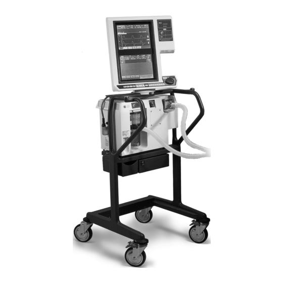
(BDU), graphic user interface (GUI), the 802 Backup Power Source (BPS), and patient system. Optional components include the 806 Compressor Unit and a ventilator cart. Figure 2-1 shows the 840 Ventilator System with the optional compressor unit and cart. -
Page 76: Breath Delivery Unit (Bdu)
Theory of operation 2.1.1 Breath delivery unit (BDU) The BDU, shown in Figure 2-2, is the core of the 840 Ventilator System. Its pneumatic system, under control of the breath delivery (BD) central processing unit (CPU), mixes oxygen and air and controls gas flow to the patient. -
Page 77: Compressor Unit
(stand-by operation) for immediate use when external compressed air is used. The compressor unit receives electrical power from and communicates with the BDU. 8-8-01132 Figure 2-4. Compressor unit 840 Ventilator System Service Manual 4-070496-00 Rev. C (06/05) -
Page 78: Backup Power Source (Bps)
The optional cart, shown in Figure 2-6, mounts system components and accessories, including the compressor unit. It also provides mobility for the ventilator. Brakes on the front casters prevent the cart from rolling and turning. 8-01119 Figure 2-6. Cart 4-070496-00 Rev. C (06/05) 840 Ventilator System Service Manual... -
Page 79: Patient System
Expiratory (To patient) Expiratory limb filter of breathing circuit Patient wye Inspiratory Collector filter vial Inspiratory limb of breathing circuit Humidifier 8-01140 Figure 2-8. NeoMode patient system 840 Ventilator System Service Manual 4-070496-00 Rev. C (06/05) -
Page 80: Operational Overview
Pressure transducers Flow sensors Oxygen regulator regulator supply Expiratory Oxygen filter supply (Expiratory (Inspiratory Inspiratory Collector limb) limb) filter vial 8-00001 Patient Humidification circuit device Figure 2-9. 840 Ventilator System block diagram 4-070496-00 Rev. C (06/05) 840 Ventilator System Service Manual... - Page 81 BDU CPU to control the PSOLs. As a result, the ventilator supplies mixed breathing gas to the patient according to operator-set variables. The mixed air and oxygen passes through the patient circuit external to the ventilator. 840 Ventilator System Service Manual 4-070496-00 Rev. C (06/05)
- Page 82 In case of a malfunction that prevents software from opening the safety valve, there is also an analog circuit that opens the safety valve if system pressure exceeds 100 to 120 cmH 4-070496-00 Rev. C (06/05) 840 Ventilator System Service Manual...
-
Page 83: Pneumatic System
Theory of operation 2.3 Pneumatic system This subsection describes the 840 Ventilator pneumatics, as follows: • Inspiratory module: Contains the following pneumatic subsystems: – Gas supply conditioning subsystem – Flow control subsystem – Safety valve/inspiration monitoring subsystem • Patient system •... -
Page 84: Figure 2-11. Pneumatic System Diagram
H P Air, Wall/Comp Humidifier Reg Air Mixed Gas Atmosphere Vacuum To Patient Water Vent PSOL1 REG1 Vent SOL1 PSOL2 REG2 Accumulator R1/F11 SOL3 Dryer 8-01145 Figure 2-11. Pneumatic system diagram 2-10 4-070496-00 Rev. C (06/05) 840 Ventilator System Service Manual... -
Page 85: Figure 2-12. Inspiratory Module
Measures oxygen or air flow before PSOL. Regulator, oxygen/air Reduces input supply pressure (35 to 100 psig, flow up to 200 L/min REG1 BTPS) to output pressure (9 psig minimum to 12 psig maximum). REG2 2-11 840 Ventilator System Service Manual 4-070496-00 Rev. C (06/05) - Page 86 Measures exhalation flow. Solenoid, autozero, expiratory +6 V, three-way solenoid valve. Energized (common to normally SOL2 pressure transducer closed) when transducer is autozeroed. De-energized (common to normally open) all other times. 2-12 4-070496-00 Rev. C (06/05) 840 Ventilator System Service Manual...
- Page 87 Water trap Collects condensate as the compressed air cools in the heat exchanger. Automatically drains collected water to the housing base where it evaporates. 2-13 840 Ventilator System Service Manual 4-070496-00 Rev. C (06/05)
-
Page 88: Inspiratory Module
Figure 2-14 is a diagram of the inspiratory module gas flow. 8-01158 Figure 2-12. Inspiratory module 8-01293 Figure 2-13. Inspiratory module in ventilator 2-14 4-070496-00 Rev. C (06/05) 840 Ventilator System Service Manual... -
Page 89: Gas Supply Conditioning Subsystem
Air pressure switch (PS2) Oxygen pressure switch (PS1) Oxygen inlet filter (F3) Check valve assembly (CV2/CV4) Water trap (WT1) Air inlet filter (F2) 8-00277 Figure 2-15. Gas supply conditioning subsystem 2-15 840 Ventilator System Service Manual 4-070496-00 Rev. C (06/05) -
Page 90: Figure 2-16. Gas Supply Conditioning Subsystem Gas Flow Diagram
• The oxygen pressure valve (TP1) checks the oxygen regulator setting (REG1). • The oxygen pneumatic noise filter (F7), housed in the flow sensor manifold, conditions gas flow by eliminating swirling of gas induced by elbows and restrictions. 2-16 4-070496-00 Rev. C (06/05) 840 Ventilator System Service Manual... - Page 91 • The air pressure valve (TP2) checks the oxygen regulator setting (REG2). • The air pneumatic noise filter (F6), housed in the flow sensor manifold, conditions gas flow by eliminating swirling of gas induced by elbows and restrictions. 2-17 840 Ventilator System Service Manual 4-070496-00 Rev. C (06/05)
-
Page 92: Figure 2-17. Gas Supply Conditioning Subsystem Components
Oxygen/air pressure switches (PS1/PS2) Oxygen inlet filter (F3) Oxygen impact filter (F1) 8-00278 Oxygen Filters (F1 and F3) 8-00278 Air inlet filter (F2) Figure 2-17. Gas supply conditioning subsystem components 2-18 4-070496-00 Rev. C (06/05) 840 Ventilator System Service Manual... - Page 93 The patient is ventilated with the remaining gas source. If both gas sources are lost, the ventilator alarms and opens the safety valve, and the patient breathes air from the room, unassisted by the ventilator. 2-19 840 Ventilator System Service Manual 4-070496-00 Rev. C (06/05)
-
Page 94: Flow Control Subsystem
The flow control subsystem, shown in Figure 2-19 and Figure 2-18, controls the mixture and flow of oxygen and air to the patient. It is mounted on the gas supply conditioning subsystem. PSOL1 PSOL2 8-00281 Figure 2-18. Flow control subsystem 2-20 4-070496-00 Rev. C (06/05) 840 Ventilator System Service Manual... -
Page 95: Figure 2-19. Flow Control Subsystem Gas Flow Diagram
Each proportional Constant solenoid valve includes a linear motor that controls a current poppet valve. The poppet valves open in proportion to Figure 2-20. Hot film the applied current. 2-21 840 Ventilator System Service Manual 4-070496-00 Rev. C (06/05) -
Page 96: Figure 2-21. Flow Control Subsystem Components
• Tidal volume (25 to 2500 mL) • Oxygen percentage (21 to 100%) • Breath rate (1 to 100/min) The PSOL control loop operates in two modes: PSOLs closed and PSOLs opened. 2-22 4-070496-00 Rev. C (06/05) 840 Ventilator System Service Manual... -
Page 97: Safety Valve And Inspiration Monitoring Subsystem
(CV3) housing Absolute pressure transducer (PA) Inspiratory pressure transducer (PI) Safety Oxygen valve (SV) sensor (OS) Inspiratory pressure transducer autozero solenoid (SOL1) 8-00152 Figure 2-22. Safety valve and inspiration monitoring subsystem 2-23 840 Ventilator System Service Manual 4-070496-00 Rev. C (06/05) -
Page 98: Figure 2-23. Inspiration Monitoring Subsystem Gas Flow Diagram
• The oxygen sensor (OS) monitors the oxygen concentration of delivered gas. This galvanic sensor generates a voltage proportional to the oxygen concentration. The ventilator alarms if the monitored oxygen concentration is not within ±7% of the oxygen percentage setting. 2-24 4-070496-00 Rev. C (06/05) 840 Ventilator System Service Manual... -
Page 99: Figure 2-24. Safety Valve And Inspiration Monitoring Subsystem Components
8-00269 Safety valve (SV) Seat Check valve Leaf housing Oxygen sensor Oxygen sensor port 8-01122 Inspiratory outlet manifold Figure 2-24. Safety valve and inspiration monitoring subsystem components 2-25 840 Ventilator System Service Manual 4-070496-00 Rev. C (06/05) - Page 100 8-00285 Absolute and inspiratory pressure transducers (PA and PI) on inspiratory electronics PCB 8-00283 Inspiratory pressure transducer autozero solenoid (SOL1) Figure 2-24: Safety valve and inspiration monitoring subsystem components (continued) 2-26 4-070496-00 Rev. C (06/05) 840 Ventilator System Service Manual...
-
Page 101: Figure 2-25. Safety Valve Open Gas Flow Diagram
PEEP plus the effective working pressure for spontaneous, pressure-supported breaths. Ongoing diagnostics monitor ventilator pressures and check for severe occlusions and circuit disconnects by comparing pressure at PE and PI. 2-27 840 Ventilator System Service Manual 4-070496-00 Rev. C (06/05) -
Page 102: Inspiratory Module Operation
Pressure relief orifice Oxygen sensor (OS) Inspiratory outlet Inspiratory pressure transducer (PI) Absolute pressure transducer (PA) Inspiratory pressure transducer autozero solenoid (SOL1) Inspiratory electronics PCB Figure 2-26. Air flow diagram 2-28 4-070496-00 Rev. C (06/05) 840 Ventilator System Service Manual... - Page 103 ±7% of the oxygen percentage setting. Pressure measurements are made by two differential pressure transducers. The inspiratory pressure transducer autozero solenoid (SOL1) is energized periodically to set a zero reference or offset voltage for the inspiration pressure transducer. 2-29 840 Ventilator System Service Manual 4-070496-00 Rev. C (06/05)
-
Page 104: Figure 2-27. Oxygen Flow Diagram
35 – 100 psig to 9 – 12 psig (10.5 psig nominal). It vents at a maximum of 2 L/min (outside the BDU to prevent oxygen buildup). 2-30 4-070496-00 Rev. C (06/05) 840 Ventilator System Service Manual... -
Page 105: Patient System
A variety of optional accessories can be used in the patient circuit. Figure 2-28 shows a typical patient system configuration. Inspiratory filter (F8) Humidification device Water trap (2 PL) 8-00276 Figure 2-28. Patient system (minus exhalation collector vial and expiratory filter) 2-31 840 Ventilator System Service Manual 4-070496-00 Rev. C (06/05) -
Page 106: Patient System Components
• The mounting plate, used only with neonatal patient systems, allows the ventilator to accommodate the neonatal expiratory filter. Caution To protect the exhalation assembly, always use a Puritan Bennett expiratory filter or a recommended DAR expiratory filter. 2-32 4-070496-00 Rev. C (06/05) -
Page 107: Patient System Operation
The exhalation valve opens and closes for exhalation and inspiration. During exhalation, the exhalation valve controls the PEEP/CPAP (baseline) pressure. A flow sensor monitors flow and a pressure transducer monitors pressure. 8-01175 Figure 2-30. Exhalation module (removed from BDU) 2-33 840 Ventilator System Service Manual 4-070496-00 Rev. C (06/05) -
Page 108: Exhalation Module Components
• The exhalation flow sensor (Q3) provides flow information on exhaled gas. Flow sensor measurements are used to determine net gas flow to the patient and spirometry. 2-34 4-070496-00 Rev. C (06/05) 840 Ventilator System Service Manual... -
Page 109: Exhalation Module Operation
The expiratory pressure transducer (PE), on the exhalation transducer PCB, and the exhalation flow sensor (Q3) provide readings used in breath delivery calculations. 2-35 840 Ventilator System Service Manual 4-070496-00 Rev. C (06/05) -
Page 110: Figure 2-32. Exhalation Module Components
8-00236 Exhalation flow sensor (Q3) Figure 2-32. Exhalation module components NOTE: Exhalation module parts are shown here for reference only. For assembly illustration, refer to Figure 9-17 on page 9-49. 2-36 4-070496-00 Rev. C (06/05) 840 Ventilator System Service Manual... - Page 111 Theory of operation 8-00287 Expiratory pressure transducer autozero solenoid (SOL2) 8-00240 Exhalation check valve (CV5) 8-00239 Exhalation heater (EXH HTR) Figure 2-32: Exhalation module components (continued) 2-37 840 Ventilator System Service Manual 4-070496-00 Rev. C (06/05)
-
Page 112: Compressor Unit
The optional, cart-mounted 806 compressor unit, shown in Figure 2-34, is the latest style compressor system available for use with the 840 ventilator. When AC power is present, the compressor system supplies air to the ventilator in the event that a hospital air source is unavailable or the source pressure drops below 26 psig. -
Page 113: Figure 2-35. 806 Components
(F11) to prevent contaminants from entering the transducer. Pressure relief valve To heat exchanger Motor/compressor Silencer Cooling fans 0.3 micron filter Silencer Intake filter Filter foam 8-01273 Figure 2-35. 806 components 2-39 840 Ventilator System Service Manual 4-070496-00 Rev. C (06/05) -
Page 114: Figure 2-36. Heat Exchanger
Figure 2-37. 806 water trap assembly To accumulator To pressure Unloading transducer (PC) solenoid (SOL3) To solenoid Filter (F10) From heat exchanger Silencer Air dryer 8-01266 Figure 2-38. Air dryer assembly 2-40 4-070496-00 Rev. C (06/05) 840 Ventilator System Service Manual... -
Page 115: Compressor Unit Operation
Figure 2-39. 806 back panel 2.3.4.2 806 Compressor unit operation The 806 compressor is powered by and communicates with the 840 BDU. The BDU sends a signal to the compressor after completing POST, and the compressor enters either stand-by mode or run mode depending upon the state of the air-side pressure switch, PS2. If PS2 is... -
Page 116: Summary Of Electrical Components
Electrical system 2.4.1 Summary of electrical components The 840 Ventilator electrical system, shown in Figure 2-41, includes the following: • AC distribution components, including power cord, AC panel (circuit breakers, AC filter PCB, power relay, and other components), and power switch •... -
Page 117: Table 2-2. Electronic Component Descriptions
Output signals from the BPS PCB include charging*, charged*, BPS model, IBATT, VBATT, and E-BP. NOTE: When the ventilator is running on battery power, the compressor and humidifier are non-operational. * indicates signal is active low 2-43 840 Ventilator System Service Manual 4-070496-00 Rev. C (06/05) - Page 118 Breath delivery (BD) CPU PCB Contains the electronics and software that control all breath delivery functions in the 840 ventilator. Communicates with the GUI CPU to respond to operator inputs and display ventilation parameters. Analog interface (AI) PCB Provides the interface for all analog signals in the ventilator. The AI and BD CPU PCBs together provide the main intelligence and drive for the mechanical devices and electronic sensors used in ventilation.
- Page 119 Delivers a voltage proportional to the oxygen concentration. Ventilator alarms if the monitored oxygen ± concentration is not within 7% of the oxygen percentage setting. 2-45 840 Ventilator System Service Manual 4-070496-00 Rev. C (06/05)
- Page 120 Motor compressor AC powered and logic-controlled, supplies compressed air to the ventilator when adequate wall air pressure is unavailable. Contains internal over-temperature protection device. 2-46 4-070496-00 Rev. C (06/05) 840 Ventilator System Service Manual...
-
Page 121: Overview Of Electrical System Operation
PCB. 2.4.2 Overview of electrical system operation The 840 Ventilator System uses a dual-microprocessor architecture with an Ethernet network as the primary channel of communication between the two 68040 microprocessors. The BDU microprocessor handles the breath delivery control and monitoring functions; the GUI microprocessor reads and interprets information from/to the operator via the keyboard, knob, and displays. - Page 122 Theory of operation This page intentionally blank. 2-48 4-070496-00 Rev. C (06/05) 840 Ventilator System Service Manual...
-
Page 123: Figure 2-41. Electrical System Block Diagram
Figure 2-41. Electrical system block diagram. Remove pages 2-49 and 2-50. (Page 2-50 is already printed on the reverse side of 11 x 17 foldout page.) Figure 2-41. Electrical system block diagram 2-49 840 Ventilator System Service Manual 4-070496-00 Rev. C (06/05) -
Page 124: Ac Distribution Components
J4, supplying AC power to the compressor unit, while the humidifier receptacle is intended to power an optional humidifier. 2.4.3.1 Power cord The 840 Ventilator System includes a detachable power cord. The power cord has an IEC- standard, three-prong connector. The plug end varies, corresponding to different country requirements. -
Page 125: Figure 2-42. Ac Panel
(compressor/ humidifier) circuit breaker Compressor (CB2) receptacle (J4) 8-00288 AC filter Main circuit breaker (CB1) Power relay (K1) Fuse Auxiliary (compressor/ humidifier circuit breaker (CB2) 8-00246 Figure 2-42. AC panel 2-51 840 Ventilator System Service Manual 4-070496-00 Rev. C (06/05) -
Page 126: Figure 2-43. 840 Ventilator System Interconnect Diagram - Ac Panel
Auxiliary mains circuit breaker Mains inlet Potential equalization point Compressor outlet To power supply compartment Power relay 8-00125 AC PANEL MODULE Figure 2-43. 840 Ventilator System interconnect diagram – AC panel 2-52 4-070496-00 Rev. C (06/05) 840 Ventilator System Service Manual... -
Page 127: Power Switch
A cover protects the power switch and prevents it from accidentally being turned off. An LED indicator beside the power switch lights to indicate that power is available to the ventilator. Power switch (S1) Indicator 8-00289 Figure 2-44. Power switch (S1) and indicator 2-53 840 Ventilator System Service Manual 4-070496-00 Rev. C (06/05) -
Page 128: Power Supply
The power supply has no test points, and cannot be field-adjusted. Power supply voltages are displayed during the analog data display test in EST. 8-00169 Figure 2-45. Power supply assembly 2-54 4-070496-00 Rev. C (06/05) 840 Ventilator System Service Manual... -
Page 129: Figure 2-46. 840 Ventilator System Interconnect Diagram - Power Distribution
To AC module panel POWER SUPPLY To backup power supply (BPS) (This side is located adjacent to inspiratory module) 8-00128 Figure 2-46. 840 Ventilator System interconnect diagram – Power distribution 2-55 840 Ventilator System Service Manual 4-070496-00 Rev. C (06/05) -
Page 130: Bps
The BPS contains a battery pack (Figure 2-48) (which includes two +12 V, lead-acid batteries and a 15 A fuse) and a PCB (Figure 2-49). 8-00199 Figure 2-47. BPS 2-56 4-070496-00 Rev. C (06/05) 840 Ventilator System Service Manual... -
Page 131: Figure 2-48. Bps Battery Pack
Theory of operation Fuse 8-00273 Figure 2-48. BPS battery pack 8-00272 Figure 2-49. BPS PCB 2-57 840 Ventilator System Service Manual 4-070496-00 Rev. C (06/05) -
Page 132: Card Cage
The card cage, shown in Figure 2-50 and Figure 2-51, includes the motherboard PCB, the BD CPU PCB, and the AI PCB. BDU CPU PCB AI PCB Motherboard PCB 8-00156 Figure 2-50. Card cage with all PCBs installed 2-58 4-070496-00 Rev. C (06/05) 840 Ventilator System Service Manual... -
Page 133: Figure 2-51. 840 Ventilator System Interconnect Diagram - Card Cage
UNIT (BDU) TEST switch (SW2) indicator GUI-to-BDU cable assy AI PCB PTS 2000 connection 9-pin BDU/compressor Data DC cable 8-00124 Figure 2-51. 840 Ventilator System interconnect diagram – Card cage 2-59 840 Ventilator System Service Manual 4-070496-00 Rev. C (06/05) -
Page 134: Motherboard Pcb
The motherboard PCB consists of a multilayer PCB, connectors for plug-in boards and I/O interface, and related electrical filters and protective devices. AI PCB connectors BD CPU PCB connectors 8-00290 Figure 2-52. Motherboard PCB 2-60 4-070496-00 Rev. C (06/05) 840 Ventilator System Service Manual... -
Page 135: Figure 2-52. Motherboard Pcb
Theory of operation Motherboard PCB 8-00157 Figure 2-53. Motherboard PCB in place 2-61 840 Ventilator System Service Manual 4-070496-00 Rev. C (06/05) -
Page 136: Figure 2-54. Motherboard Pcb Block Diagram
TO/FROM EXHALATION MODULE BD ALARM +12 V EXH AZ EXH MODULE CTRL INSP MOD PWR & SENS TO/FROM INSPIRATORY INSP MODULE CTRL MODULE 8-00300 Figure 2-54. Motherboard PCB block diagram 2-62 4-070496-00 Rev. C (06/05) 840 Ventilator System Service Manual... -
Page 137: Bdu Cpu Pcb
The BD CPU PCB (Figure 2-55), in conjunction with the AI PCB, provides microprocessor control of all breath delivery functions for the 840 Ventilator System. It also communicates with the GUI CPU PCB for display and control information from the operator. All analog signals to and from the sensors and actuators of the system are controlled by software running in the BD CPU. - Page 138 • A diagnostic LED array (with supporting circuitry) indicates the status of the BD CPU PCB. During POST, they indicate the current test step. A ninth LED displays the supervisory mode status of the CPU. 2-64 4-070496-00 Rev. C (06/05) 840 Ventilator System Service Manual...
- Page 139 • The service mode switch is a push-button on the board edge used to activate this mode. The BD CPU PCB generates an NMI under any of these conditions: • Ethernet parity error detected • Power fail signal • A/D converter system error 2-65 840 Ventilator System Service Manual 4-070496-00 Rev. C (06/05)
-
Page 140: Table 2-3. Novram Contents
Calculated during SST BD NOVRAM expiratory resistance Oxygen and air flow Calculated during EST BD NOVRAM sensor (Q1 and Q2) offsets Absolute pressure Calculated during PA calibration BD NOVRAM transducer (PA) offset 2-66 4-070496-00 Rev. C (06/05) 840 Ventilator System Service Manual... -
Page 141: Analog Interface (Ai) Pcb
• The valve control and drive circuit provides drive signals for the PSOLs, EV, and the EV stabilizer device. PTS 2000 connector Data key connector Compressor connector AI LEDs 8-00267 Figure 2-56. AI PCB 2-67 840 Ventilator System Service Manual 4-070496-00 Rev. C (06/05) - Page 142 • Other buffers provide conditioning for various ventilator signals. • The compressor interface circuit, in conjunction with the compressor PCB, controls and monitors the compressor operation. 2-68 4-070496-00 Rev. C (06/05) 840 Ventilator System Service Manual...
-
Page 143: Data Key Subsystem
Call your Puritan Bennett representative if the data key requires replacement due to loss or failure. The 840 Ventilator System uses a data key (Figure 2-57) to record data specific to a particular ventilator unit. The data key provides a way to retain data when PCBs or the battery are removed from the ventilator. -
Page 144: Figure 2-58. 10.4" Gui Cpu Pcb
Theory of operation Figure 2-58. 10.4” GUI CPU PCB GUI CPU Backlight inverter PCB 8-00166 Figure 2-59. 9.4” GUI CPU PCB and backlight inverter PCB in place 2-70 4-070496-00 Rev. C (06/05) 840 Ventilator System Service Manual... - Page 145 • Three RS-232 C channels provide output for digital communications interface and external communications for service mode. They are electrically isolated for safety. The 9.4-inch GUI has only one RS-232 channel, also electrically isolated. 2-71 840 Ventilator System Service Manual 4-070496-00 Rev. C (06/05)
-
Page 146: Figure 2-60. 840 Ventilator System Interconnect Diagram - Gui 10.4-Inch Lcd Panels
To BDU RS-232 Remote alarm Keyboard cable assy Rear of keyboard Touch frame cable assy GUI MODULE GUI10_4wiring Figure 2-60. 840 Ventilator System interconnect diagram – GUI 10.4-inch LCD panels 2-72 4-070496-00 Rev. C (06/05) 840 Ventilator System Service Manual... - Page 147 The GUI CPU PCB generates an NMI under any of these conditions: • GUI +5 V is high • GUI +12 V is out of range • Ethernet parity error detected • SAAS microcontroller failure 2-73 840 Ventilator System Service Manual 4-070496-00 Rev. C (06/05)
-
Page 148: Figure 2-61. 840 Ventilator System Interconnect Diagram - Gui 9.4-Inch Lcd Panels
To BDU RS-232 Remote alarm Keyboard cable assy Rear of keyboard Touch Frame cable assy GUI MODULE 8-00122 Figure 2-61. 840 Ventilator System interconnect diagram – GUI 9.4-inch LCD panels 2-74 4-070496-00 Rev. C (06/05) 840 Ventilator System Service Manual... -
Page 149: Touch Frame Pcb
During normal conditions, when all LEDs and IR detectors are functioning properly, the redundant detectors are used to provide a more accurate output by averaging the locations of the blocked beams. 2-75 840 Ventilator System Service Manual 4-070496-00 Rev. C (06/05) -
Page 150: Keyboard Assembly With Knob
The multiposition knob assembly, which is part of the keyboard assembly, permits ventilator setting selections or changes. Knob encoder/decoder circuitry on the GUI CPU PCB determines the direction and position of the shaft based on encoder outputs. 2-76 4-070496-00 Rev. C (06/05) 840 Ventilator System Service Manual... -
Page 151: Figure 2-63. Keyboard Assembly
Theory of operation Figure 2-63. Keyboard assembly 2-77 840 Ventilator System Service Manual 4-070496-00 Rev. C (06/05) -
Page 152: Gui Led Pcb
(except "compressor operating" and "on BPS power") includes redundant LED strings so the indicators will stay lit if an LED bar burns out. 8-00294 Figure 2-64. GUI LED PCB 2-78 4-070496-00 Rev. C (06/05) 840 Ventilator System Service Manual... -
Page 153: 5Backlight Inverter Pcb And Lcd Lamps
LCD panels simultaneously. The LCD lamps are part of the 10,000-hour preventive maintenance kit on the 9.4-inch GUI. Figure 2-65. 10.4” GUI LCD panels 2-79 840 Ventilator System Service Manual 4-070496-00 Rev. C (06/05) -
Page 154: Gui Alarm Assembly
2.4.8.6 GUI alarm assembly The GUI alarm assembly (Figure 2-67), the ventilator’s primary alarm, emits alarm sounds under control of the GUI CPU PCB. 8-00295 Figure 2-67. GUI alarm assembly 2-80 4-070496-00 Rev. C (06/05) 840 Ventilator System Service Manual... -
Page 155: Bdu Led Pcb
• The absolute pressure transducer (PA) senses absolute pressure in the inspiratory module. It is used to determine atmospheric pressure for volume delivery. • The oxygen sensor (OS) amplifier provides an interface for the oxygen concentration sensor mounted on the PCB. 2-81 840 Ventilator System Service Manual 4-070496-00 Rev. C (06/05) -
Page 156: Figure 2-70. 840 Ventilator System Interconnect Diagram - Inspiratory Module
4-071321-00 Press switch harness assy 4-071326-00 Air pressure Oxygen pressure switch (PS1) switch (PS2) 4-072206-00 4-072206-00 INSPIRATORY MODULE 8-00123 Figure 2-70. 840 Ventilator System interconnect diagram – Inspiratory module 2-82 4-070496-00 Rev. C (06/05) 840 Ventilator System Service Manual... -
Page 157: Exhalation Transducer Pcb
(PE), which is on this PCB, senses the pressure difference in the exhalation circuit relative to ambient air pressure. The PCB uses a +10 V reference. 8-00296 Figure 2-71. Exhalation transducer PCB 2-83 840 Ventilator System Service Manual 4-070496-00 Rev. C (06/05) -
Page 158: Figure 2-72. 840 Ventilator System Interconnect Diagram - Exhalation Module
Exhalation module Exhalation I/O cable assy cable assy Expiratory Exhalation pressure transducer valve (PE) Exhalation transducer PCB 8-00126 EXHALATION MODULE Figure 2-72. 840 Ventilator System interconnect diagram – Exhalation module 2-84 4-070496-00 Rev. C (06/05) 840 Ventilator System Service Manual... -
Page 159: 1Bd (Continuous-Tone) Alarm Assembly
The 806 compressor unit’s electrical components include: AC power distribution components, a compressor motor, and a compressor PCB. The compressor unit is shown in Figure 2-74. 8-01257 Figure 2-74. 806 compressor 2-85 840 Ventilator System Service Manual 4-070496-00 Rev. C (06/05) -
Page 160: 1806 Compressor Unit Ac Power Distribution Components And Motor
PCB’s primary function is to control the pressure of the air delivered to the ventilator when wall air is not present or is insufficient. Data cable Power Pressure cord transducer hose Solenoid cable Compressor cable cables Ground 8-01272 Figure 2-76. 806 compressor PCBA installed 2-86 4-070496-00 Rev. C (06/05) 840 Ventilator System Service Manual... - Page 161 Section 2.4.12.3 describes how this logic controls compressor component operation. This logic shuts off the compressor when AC is inadequate or the thermostat on the PCB detects overtemperature. 2-87 840 Ventilator System Service Manual 4-070496-00 Rev. C (06/05)
-
Page 162: Figure 2-77. 806 Compressor Pcb Block Diagram
CAPACITOR MOTOR COMP COMPRESSOR CONTROL HOUSING CKTS TO/FROM AI PANEL EEPROM CKTS COMP OVER TEMP +5 V COMP THERMOSTAT +12 V COMP 806compbd Figure 2-77. 806 compressor PCB block diagram 2-88 4-070496-00 Rev. C (06/05) 840 Ventilator System Service Manual... -
Page 163: Figure 2-78. 840 Ventilator System Interconnect Diagram - Compressor Unit
840 Ventilator System interconnect diagram – Compressor unit Remove pages 2-89 and 2-90. (Page 2-90 is also printed on the reverse side of the foldout.) Figure 2-78. 840 Ventilator System interconnect diagram – Compressor unit 2-89 840 Ventilator System Service Manual... -
Page 164: 3806 Compressor Unit Operation
If pressure in the accumulator drops below 22.5 psig (due to small leaks in the system or cooling of compressed air), the compressor starts and recharges the accumulator to 27 psig (see Figure 2-79). 2-90 4-070496-00 Rev. C (06/05) 840 Ventilator System Service Manual... -
Page 165: Figure 2-79. Compressor Operational Sequence
After 1 second, a solid-state relay on the PCB is energized. After another 0.5 seconds, SOL3 is de-energized. 2-91 840 Ventilator System Service Manual 4-070496-00 Rev. C (06/05) -
Page 166: Breath Delivery
The ventilator delivers two types of breath: mandatory and spontaneous. A breath cycle includes inspiration and exhalation phases. The ventilator uses operator settings input through the GUI to determine breath type and parameters. Consult the 840 Ventilator System Operator’s and Technical Reference Manual for a clinical perspective on breath delivery. NOTE: •... -
Page 167: Figure 2-81. Inspiration Gas Flow Diagram
H P Air, Wall/Comp Humidifier Reg Air Mixed Gas Atmosphere Vacuum To Patient Water Vent PSOL1 REG1 Vent SOL1 PSOL2 REG2 Accumulator R1/F11 SOL3 Dryer i8-01288 Figure 2-81. Inspiration gas flow diagram 2-93 840 Ventilator System Service Manual 4-070496-00 Rev. C (06/05) -
Page 168: 1Pressure Triggering
Backup limits (time, circuit pressure, and ventilator pressure) prevent inspirations of excessive duration or pressure. If a particular breath is subject to more than one backup limit, exhalation is triggered by whichever method goes into effect first. 2-94 4-070496-00 Rev. C (06/05) 840 Ventilator System Service Manual... -
Page 169: 1Time-Cycling Method
2.5.2.6 High ventilator pressure limit The high ventilator pressure limit applies to volume-based mandatory breaths only. If the inspiratory pressure (measured at PI) equals or exceeds 100 cmH O, the ventilator transitions to exhalation. 2-95 840 Ventilator System Service Manual 4-070496-00 Rev. C (06/05) -
Page 170: Figure 2-82. Exhalation Gas Flow Diagram
H P Air, Wall/Comp Humidifier Reg Air Mixed Gas Atmosphere Vacuum To Patient Water Vent PSOL1 REG1 Vent SOL1 PSOL2 REG2 Accumulator R1/F11 SOL3 Dryer 8-01285 Figure 2-82. Exhalation gas flow diagram 2-96 4-070496-00 Rev. C (06/05) 840 Ventilator System Service Manual... -
Page 171: Other Hardware Operations
(exhaled tidal volume) to be transiently displayed as lower or higher than the actual exhaled volume. This is a result of initial spirometry calculations and does not reflect actual volume exhaled by the patient. 2-97 840 Ventilator System Service Manual 4-070496-00 Rev. C (06/05) -
Page 172: Pressure Transducer Autozero
Autozeroing is performed every minute for 20 minutes; every 2 minutes after 20 minutes, up to one hour; and every 5 minutes after 1 hour. 2-98 4-070496-00 Rev. C (06/05) 840 Ventilator System Service Manual... -
Page 173: Figure 2-83. Pressure Transducer Autozero Mode Gas Flow Diagram
Reg Air Mixed Gas Atmosphere Vacuum To Patient Water Vent PSOL1 REG1 Vent SOL1 PSOL2 REG2 Accumulator R1/F11 SOL3 Dryer 8-01142 Figure 2-83. Pressure transducer autozero mode gas flow diagram 2-99 840 Ventilator System Service Manual 4-070496-00 Rev. C (06/05) -
Page 174: Power Monitoring And Power Fail Handling
(generated by power fail) BPS: 30 minutes minimum Ext. battery: 60 minutes minimum prior to switching to BPS (with new fully charged battery) Figure 2-84. Power loss sequence 2-100 4-070496-00 Rev. C (06/05) 840 Ventilator System Service Manual... -
Page 175: Supply Voltage Monitoring
• Displays the elapsed time since the loss of ventilatory support on the GUI • Does not display patient data, including waveforms, on the GUI • Does not detect patient circuit occlusion or disconnect conditions 2-101 840 Ventilator System Service Manual 4-070496-00 Rev. C (06/05) -
Page 176: Figure 2-85. Safety Valve Open Diagram
H P Air, Wall/Comp Humidifier Reg Air Mixed Gas Atmosphere Vacuum To Patient Water Vent PSOL1 REG1 Vent SOL1 PSOL2 REG2 Accumulator R1/F11 SOL3 Dryer 8-01143 Figure 2-85. Safety valve open diagram 2-102 4-070496-00 Rev. C (06/05) 840 Ventilator System Service Manual... -
Page 177: Occlusion Handling
During a severe occlusion, apnea detection, expiratory pause, manual inspirations, and maneuvers are suspended, and the ↑ P (high airway pressure) alarm limit is disabled. MEAN The GUI does allow you to change ventilator settings. 2-103 840 Ventilator System Service Manual 4-070496-00 Rev. C (06/05) -
Page 178: Figure 2-86. Pressure Release, Patient Circuit Occluded Diagram
Humidifier Reg Air Mixed Gas Atmosphere Vacuum To Patient Water Vent PSOL1 REG1 Vent SOL1 PSOL2 REG2 Accumulator R1/F11 SOL3 Dryer 8-01144 Figure 2-86. Pressure release, patient circuit occluded diagram 2-104 4-070496-00 Rev. C (06/05) 840 Ventilator System Service Manual... -
Page 179: Self Tests
TEST button while entering service mode. 3.3 Self tests and background checks The 840 Ventilator has self test capabilities that include POST (power-on self test), SST (short self test), EST (extended self test), and background checks. These self test operations are described in Table 3-1, and Table 3-2 details the components tested by various self tests. -
Page 180: Est (Extended Self Test)
EST requires a “gold standard” test circuit, available from Puritan Bennett. All required software support to perform an EST is resident on the ventilator. EST testing, excluding tests of optional equipment, such as the compressor, takes about 15 minutes to complete. -
Page 181: Power On Self Test (Post)
AC monitor voltage Supply voltages (including BDU and GUI voltages) BPS supply voltage/current BPS charging and discharging BPS model Patient system Patient circuit leak Patient circuit occlusions/resistance Patient circuit compliance Expiratory filter occlusion/resistance 840 Ventilator System Service Manual 4-070496-00 Rev. C (06/05) - Page 182 Oxygen and air PSOL forward leak Oxygen and air PSOLs stuck open or stuck in other position Inspiration and exhalation pressure transducer autozero solenoids Inspiration pressure transducer Exhalation pressure transducer Inspiration and exhalation pressure transducer cross-check 4-070496-00 Rev. C (06/05) 840 Ventilator System Service Manual...
-
Page 183: Table 3-1. Self Tests
Audio alarm and user interface sound- producing subsystem Alarm cable (BDU) Nurse’s call relay +10 V reference (used by ADCs and DACs) ADC/DAC functionality Power fail capacitor 840 Ventilator System Service Manual 4-070496-00 Rev. C (06/05) - Page 184 POST routines are ordered so that each routine requires successively more operational hardware than the last. This sequence allows POST to systematically exclude electronic components as causes of system malfunctions. 4-070496-00 Rev. C (06/05) 840 Ventilator System Service Manual...
-
Page 185: Safety
POST’s memory test preserves all data necessary to determine ventilator settings and initializes the remaining memory to a predefined state. • Any other processors in the system initiates its own POST and reports the test results to the host processor. 840 Ventilator System Service Manual 4-070496-00 Rev. C (06/05) -
Page 186: Post Following Power Interruptions
POST. NOTE: Puritan Bennett recommends that a BPS is always installed on the ventilator. If there is a loss of AC power with a charged BPS installed, the ventilator will switch to the DC source and will not run POST upon restoration of AC power. -
Page 187: Structure Of Post
• POST continues to end. • Minor fault detected. • Check System Diagnostic Log for any associated error codes. • Ventilation proceeds. • Rerun POST/EST. • A DEVICE ALERT is annunciated. 840 Ventilator System Service Manual 4-070496-00 Rev. C (06/05) -
Page 188: Table 3-3. Post Structure
OFF turned on then off • No audible alarms/ tone alarm ON (2 beeps if OK) LEDs active • BDU continuous tone alarm turned on and off twice 3-10 4-070496-00 Rev. C (06/05) 840 Ventilator System Service Manual... - Page 189 (including POST 10 second timer). 3-11 840 Ventilator System Service Manual 4-070496-00 Rev. C (06/05)
-
Page 190: Sst (Short Self Test)
10 minutes in service mode before running SST, to ensure accurate testing. • Puritan Bennett recommends that you run SST every 15 days, between patients, after a major service or repair (refer to Table 5-2 on page 6), and when you change the patient circuit. -
Page 191: Hardware Requirements
Self tests 3.5.2 Hardware requirements Running SST requires the equipment listed in Table 3-5. Table 3-5: Hardware requirements for SST Manufacturer or model or Puritan Bennett part Description number Patient circuit Varies NOTE: To ensure that compliance compensation functions correctly, the user must run SST with the circuit configured as intended for use on the patient. -
Page 192: Running Sst
(Block wye when prompted by SST) 8-01210 Figure 3-1. Patient circuit setup for SST At SST Setup screen (lower GUI screen), select patient circuit and humidification types, then press ACCEPT. 3-14 4-070496-00 Rev. C (06/05) 840 Ventilator System Service Manual... - Page 193 To begin normal ventilation (if SST has not detected an ALERT or FAILURE), touch EXIT SST, then press ACCEPT. The ventilator reruns POST, then displays the Ventilator Startup screen. 3-15 840 Ventilator System Service Manual 4-070496-00 Rev. C (06/05)
-
Page 194: Table 3-6. Sst Tests
Overriding an ALERT could cause inaccurate patient pressure estimation. FAILURE if test detects exhalation compartment occlusion, expiratory filter occlusion or damage, or you did not follow prompts to detach and reattach tubing correctly. 3-16 4-070496-00 Rev. C (06/05) 840 Ventilator System Service Manual... -
Page 195: Table 3-7. Sst Individual Test Results
Exit SST in order to service ventilator or review error codes by condition is declared. pressing EXIT SST. OVERRIDDEN An ALERT status was overridden, Touch EXIT SST. and ventilation is authorized. 3-17 840 Ventilator System Service Manual 4-070496-00 Rev. C (06/05) -
Page 196: Est (Extended Self Test)
3.6.1 Description of EST Table 3-10 lists the tests that comprise EST. For more details about these tests and associated diagnostic codes, see Section 6. For a theory of operation of EST, consult the 840 Ventilator System Operator’s and Technical Reference Manual. -
Page 197: Hardware Requirements
The ventilator automatically enters the service mode. Do not continue to depress or cycle the TEST button while entering service mode. c. On lower screen, touch EST. 3-19 840 Ventilator System Service Manual 4-070496-00 Rev. C (06/05) -
Page 198: Figure 3-2. Est Setup
You can touch EXIT EST during EST to halt testing. You can touch EXIT EST again to resume testing, or press ACCEPT to restart the ventilator (if EST has not detected an ALERT or FAILURE). 3-20 4-070496-00 Rev. C (06/05) 840 Ventilator System Service Manual... - Page 199 When all of the tests in EST are complete, the Extended Self Test screen displays all individual test results and EST outcome. Refer to Tables Table 3-10, Table 3-11, and Table 3-12 for additional information. 3-21 840 Ventilator System Service Manual 4-070496-00 Rev. C (06/05)
-
Page 200: Figure 3-3. Est Screens During Testing
Self tests 08:28 18 Jul 2003 18 Jul 03 18 Jul 03 Figure 3-3. EST screens during testing 3-22 4-070496-00 Rev. C (06/05) 840 Ventilator System Service Manual... -
Page 201: Table 3-10. Est Tests
Verifies that GUI LEDs are functioning by prompting the Observe GUI indicators and press operator to acknowledge that the LEDs are turned on. ACCEPT (if on) or CLEAR (if not on). 3-23 840 Ventilator System Service Manual 4-070496-00 Rev. C (06/05) - Page 202 • If AC is not connected, connect AC power as directed. Compressor Load Test Tests compressor operation. This test checks the compressor’s ability to maintain sufficient air pressure during worst-case breath delivery (200 lpm). 3-24 4-070496-00 Rev. C (06/05) 840 Ventilator System Service Manual...
-
Page 203: Table 3-11. Est Individual Test Results
Repeat EST from the beginning by touching RESTART EST. the failed test. Exit EST in order to service ventilator or review error codes by touching EXIT EST. 3-25 840 Ventilator System Service Manual 4-070496-00 Rev. C (06/05) -
Page 204: Table 3-12. Overall Est Outcomes
A ventilator inoperative Exit EST in order to service ventilator or review error codes by condition is declared. touching EXIT EST. OVERRIDDEN An ALERT status was overridden. Touch EXIT EST. 3-26 4-070496-00 Rev. C (06/05) 840 Ventilator System Service Manual... -
Page 205: Service Mode
E C T I O N Service mode The 840 Ventilator System operates in two modes: patient ventilation and service mode. The service mode is intended for use by a trained service technician to aid in ventilator testing and troubleshooting and to perform system calibrations. - Page 206 Service mode Figure 4-1. SERVICE MODE screens 4-070496-00 Rev. C (06/05) 840 Ventilator System Service Manual...
-
Page 207: Service Mode Functions
Displays the details of the last EST run. Runs EST to thoroughly test the operational integrity of the ventilator, both electronics and pneumatics. DATE/TIME Adjusts current date and time. EXIT Exits service mode. Other Screens Performs miscellaneous service, test, and calibration functions. 840 Ventilator System Service Manual 4-070496-00 Rev. C (06/05) -
Page 208: Figure 4-2. Service Mode Functions
Mode Setup Test Control Calibration Test Calibration Update Test Transducer (10.4 GUI only) Calibration External Nominal Pressure Control Line Voltage Unit Baud Rate 8-00210 LOWER SCREEN Figure 4-2. Service mode functions 4-070496-00 Rev. C (06/05) 840 Ventilator System Service Manual... -
Page 209: Sst Result: Displaying Sst Results
NOTE: System Diagnostic Information and EST/SST Diagnostic logs can only be erased by using the 840 VTS Breath Labs Software. The alarm log is automatically erased each time a new patient is setup is selected and when EST is run. -
Page 210: Figure 4-3. System Information Log
Service mode Figure 4-3. System Information Log Figure 4-4. EST/SST Diagnostic Log 4-070496-00 Rev. C (06/05) 840 Ventilator System Service Manual... -
Page 211: Alarm Log: Displaying The Alarm History
This function lets you adjust the current date and time. Any change is recorded in the information and diagnostic logs. 4.2.9 EXIT: Exiting service mode This function lets you exit the service mode. 840 Ventilator System Service Manual 4-070496-00 Rev. C (06/05) -
Page 212: Other Screens
O or hPa). External Test Control Lets you test the ventilator using a computer, 840 VTS Breath Labs Software, and PTS 2000 tester, to run performance verification. Also used to download new application software to the 840. Exp Valve Calibration Performs calibration. -
Page 213: Exp Valve Calibration
Calibration failed: current limit exceeded Failure Exhalation valve and/or analog interface PCB may be out of specification. Calibration failed: gain resolution Failure Exhalation valve and/or analog interface PCB may be out of specification. 840 Ventilator System Service Manual 4-070496-00 Rev. C (06/05) - Page 214 Flow controller is not able to establish a 5 L/min test flow via the exhalation flow sensor. Unable to program flash Failure Unable to program calibration table into BDU NOVRAM. Check BDU +12 V supply and BDU CPU PCB. 4-10 4-070496-00 Rev. C (06/05) 840 Ventilator System Service Manual...
-
Page 215: Vent Inop Test
Troubleshoot as indicated in Table 4-6. You must repeat the Vent Inop Test and pass it with no failures before ventilation is allowed. 4-11 840 Ventilator System Service Manual 4-070496-00 Rev. C (06/05) -
Page 216: Flow Sensor Calibration
If the calibration fails, make sure that the test circuit is attached and that the expiratory filter is securely connected and free of leaks, then try rerunning it. If the calibration continues to fail, refer to Table 4-7 to troubleshoot any errors. 4-12 4-070496-00 Rev. C (06/05) 840 Ventilator System Service Manual... -
Page 217: Running Flow Sensor Calibration
Allow the barometric pressure reading to stabilize, then touch the button and turn the knob to enter the pressure (in mmHg) measured by this external barometer, as prompted. (1 mmHg = 1.333 mbars = 133.33 Pa = 0.019 psia.) 4-13 840 Ventilator System Service Manual 4-070496-00 Rev. C (06/05) -
Page 218: Automatically Executed Service Mode Functions
GUI did not receive all calibration data from BDU within 10 s. Check BDU/GUI cable, BD CPU PCB, or GUI CPU PCB. Unable to burn flash GUI NOVRAM cannot be successfully programmed. Check GUI CPU PCB. 4-14 4-070496-00 Rev. C (06/05) 840 Ventilator System Service Manual... -
Page 219: Serial Number Setup
BDU serial number in NOVRAM is set to the default, but the GUI serial number in NOVRAM is unaffected. • Do not use the same data key to initialize the serial numbers in more than one ventilator. 4-15 840 Ventilator System Service Manual 4-070496-00 Rev. C (06/05) -
Page 220: Datakey Update
Other Screens button, then the Operational Time Log button. The correct operational hours should be displayed. If the wrong operational hours are displayed, refer to Table 4-11 to correct the problem. 4-16 4-070496-00 Rev. C (06/05) 840 Ventilator System Service Manual... -
Page 221: Serial Loopback Test
4. If correct, repeat the datakey update. 5. If problem persists, you must obtain a duplicate datakey containing the correct serial numbers and software options from your Puritan Bennett representative. 4.2.19 Serial Loopback Test On the 10.4-inch GUI only, use the Serial Loopback Test to check the function of the serial ports on the back of the GUI. - Page 222 Service mode This page intentionally blank. 4-18 4-070496-00 Rev. C (06/05) 840 Ventilator System Service Manual...
-
Page 223: Performance Verification
Field performance verification testing includes electrical safety tests, the extended self test (EST), plus specific performance verification tests, using the Puritan Bennett PTS 2000 Performance Test System with 840 VTS software. A manual ventilator check can be performed to check general ventilator performance. -
Page 224: Table 5-1. Tools, Equipment, And Service Materials Required For
See Table 1-10 for acceptable products. Double banana jack for ground isolation test Pomona Electronics, P/N 1330-2 * These parts may be purchased individually or by ordering an 840 VTS Accessories Kit, P/N 4-076599-00. 4-070496-00 Rev. C (06/05) 840 Ventilator System Service Manual... - Page 225 Serial Card, Socket I/O Ruggedized or equivalent (Provides second Socket Communications Corp. serial port) Newark, CA http://www.socketcom.com/ * These parts may be purchased individually or by ordering an 840 VTS Accessories Kit, P/N 4-076599-00. 840 Ventilator System Service Manual 4-070496-00 Rev. C (06/05)
-
Page 226: Preliminary Ventilator Cleaning And Inspection
Local supplier and laser printers) Wye, patient circuit *4-000338-00 * These parts may be purchased individually or by ordering an 840 VTS Accessories Kit, P/N 4-076599-00. 5.3 Preliminary ventilator cleaning and inspection Clean and inspect the ventilator as follows: Warning To prevent disease transmission, use personal protective equipment when handling contaminated bacterial filters or other patient accessories. -
Page 227: Preliminary Ventilator Setup
5.5 Preliminary calibrations and tests Before running the performance verification tests, perform the applicable calibrations and tests in Table 5-2. The numbers in the columns indicate the sequence in which the calibrations/tests must be performed. 840 Ventilator System Service Manual 4-070496-00 Rev. C (06/05) -
Page 228: Table 5-2. Pre-Performance Verification Testing And Calibration Requirements
• No functional hardware repairs are conducted or required during the software update service call. Unless the ventilator meets all of these requirements, PVT must be performed following the repair. 4. Perform EST and electrical safety testing only. 4-070496-00 Rev. C (06/05) 840 Ventilator System Service Manual... -
Page 229: Performance Verification Guidelines
NOTE: To ensure that the ventilator performs within specifications, Puritan Bennett recommends that you use the Puritan Bennett PTS 2000 Performance Test System in conjunction with the BreathLab 840 Verification Test Software. If this equipment is not available, you can use an alternative test that checks some parameters but does not guarantee the integrity of the entire system. -
Page 230: Electrical Safety Test
Set the DMM to the 1Ω setting and VERIFY that resistance between pin 3 of PTS 2000 tester port (on the AI PCB) and ventilator chassis (at the power supply cooling fins) is > 975Ω. Disconnect DMM test leads and resistor. 4-070496-00 Rev. C (06/05) 840 Ventilator System Service Manual... -
Page 231: Extended Self Test (Est)
Attach appropriate regulator calibration hose to pneumatic analyzer, and verify that analyzer does not register pressure. Remove air side test port cover and set aside. Attach hose to test port. Verify that analyzer reads 10.5 ± 1.5 psi. 840 Ventilator System Service Manual 4-070496-00 Rev. C (06/05) -
Page 232: Serial Loopback Test (10.4-Inch Gui Only)
• If you are using a pneumatic analyzer other than the PTS 2000 Performance Test System, you must also have an oxygen analyzer available. • The manual ventilator check (i.e., without PTS 2000 PTS and 840 VTS software) does not satisfy the manufacturer’s performance testing requirements. The manual ventilator check can be used as a general indicator of ventilator condition. -
Page 233: Regulator Calibration Hose Repair Instructions
(P/N 4-026790-00) and push the assembly into end of the brass fitting, ensuring that the seal is flush with the end of the brass fitting. Valve depressor Brass regulator fitting 1/4” silicone tubing Figure 5-1. Regulator calibration hose repair 5-11 840 Ventilator System Service Manual 4-070496-00 Rev. C (06/05) - Page 234 Performance verification This page intentionally blank. 5-12 4-070496-00 Rev. C (06/05) 840 Ventilator System Service Manual...
-
Page 235: Diagnostic Codes
This section contains the following reference tables: Table Page Table 6-1: Values of diagnostic code digits Table 6-2: 840 Ventilator diagnostic codes Table 6-3: Address codes for BDU POST analog devices test errors 6-54 Table 6-4: BDU and GUI—Phase 1 (kernel) POST diagnostic codes 6-55 Table 6-5: BDU only—Phase 2 POST diagnostic codes... -
Page 236: Troubleshooting
• Replace BD or GUI CPU PCB only after all other remedies have been attempted. Contact Puritan Bennett Technical Support for further assistance. • Check for system leaks, particularly at the expiratory filter. Make sure the expiratory filter collector vial is secured tightly, the drain port is capped, and the filter is mounted securely to the ventilator. -
Page 237: Diagnostic Cpu Led Arrays
6.5 Diagnostic CPU LED arrays The diagnostic LED arrays, resident on the BD and GUI CPU PCBs, report diagnostic codes for background check and POST self test faults that may assist in troubleshooting the 840 ventilator. To view the BD diagnostic LED array, you must disconnect the GUI cable from the BDU and remove the BDU exhalation module cover (Section 8.15.9.2). -
Page 238: Diagnostic Codes
GUI problem that resulted in soft reset during operation GUI failure (during POST or background check) caused GUI or ventilator inoperative condition POST or background check alert or communication error in GUI 4-070496-00 Rev. C (06/05) 840 Ventilator System Service Manual... -
Page 239: Organization Of Diagnostic Codes Table
Other error identification information 6.7 Organization of diagnostic codes table Table 6-2 is a comprehensive summary of the diagnostic codes that the 840 software can report. The organization of the information in this table is as follows: • The first column in the table lists, in alphanumeric order, the codes. - Page 240 • Replace BD or GUI CPU PCB only after all other remedies have been attempted. Contact Puritan Bennett Technical Support for further assistance. • Check for system leaks, particularly at the expiratory filter. Make sure the expiratory filter collector vial is secured tightly, the drain port is capped, and the filter is mounted securely to the ventilator.
-
Page 241: Table 6-2. 840 Ventilator Diagnostic Codes
Diagnostic codes Table 6-2: 840 Ventilator diagnostic codes Message Information / possible Code Test Response Corrective action displayed cause AE0110 Unable to EST Flow Alert Flow controller unable 1. Make sure oxygen supply is establish O sensors cross to establish and control connected and unrestricted. - Page 242 Diagnostic codes Table 6-2: 840 Ventilator diagnostic codes (continued) Message Information / possible Code Test Response Corrective action displayed cause AE0306 Test circuit not EST Leak Test Alert Pressure not detected 1. Make sure test circuit is prop- connected on expiratory side erly connected.
- Page 243 Diagnostic codes Table 6-2: 840 Ventilator diagnostic codes (continued) Message Information / possible Code Test Response Corrective action displayed cause AE0611 GUI Screen Lock EST GUI Lamp Alert CLEAR key pressed to 1. Check/replace interconnect LED fails. Test indicate LED not on.
- Page 244 Diagnostic codes Table 6-2: 840 Ventilator diagnostic codes (continued) Message Information / possible Code Test Response Corrective action displayed cause AE1104 Insp check valve EST Safety Alert It took too little time to 1. Make sure test circuit is con-...
- Page 245 Diagnostic codes Table 6-2: 840 Ventilator diagnostic codes (continued) Message Information / possible Code Test Response Corrective action displayed cause AE1604 Run mode time Alert Compressor timer is not Listen for motor. If motor is on, Compressor running while replace compressor PCB.
- Page 246 Diagnostic codes Table 6-2: 840 Ventilator diagnostic codes (continued) Message Information / possible Code Test Response Corrective action displayed cause AE1701 Unable to Alert Compressor leak test 1. Troubleshoot accompanying perform Compressor cannot be run, because code AE1604 or AE1607.
- Page 247 Diagnostic codes Table 6-2: 840 Ventilator diagnostic codes (continued) Message Information / possible Code Test Response Corrective action displayed cause AE2103 Bad Backup EST Battery Test Alert While BPS was 1. Ensure that the battery pack is Power Supply discharging, BPS...
- Page 248 Diagnostic codes Table 6-2: 840 Ventilator diagnostic codes (continued) Message Information / possible Code Test Response Corrective action displayed cause AS0011 Unable to SST flow sensor Alert 1. Flow controller 1. Make sure air supply is con- establish air flow...
- Page 249 Diagnostic codes Table 6-2: 840 Ventilator diagnostic codes (continued) Message Information / possible Code Test Response Corrective action displayed cause AS0311 Low expiratory SST Expiratory Alert Pressure drop 1. Repeat test, following direc- filter ΔP filter across expiratory filter tions more closely.
- Page 250 Diagnostic codes Table 6-2: 840 Ventilator diagnostic codes (continued) Message Information / possible Code Test Response Corrective action displayed cause AS0507 Compliance low SST Alert High compliance falls 1. Make sure correct patient tub- Compliance below 1.56 mL/cmH ing type was specified in SST.
- Page 251 Diagnostic codes Table 6-2: 840 Ventilator diagnostic codes (continued) Message Information / possible Code Test Response Corrective action displayed cause NOTE: For all "FE" codes (failures reported during EST), diagnose the problem and perform the repair. Run a complete EST to reset the EST test failure in memory. If there is a failed EST test result in memory, normal operation is prevented until the failed EST test is rerun and passes.
- Page 252 Diagnostic codes Table 6-2: 840 Ventilator diagnostic codes (continued) Message Information / possible Code Test Response Corrective action displayed cause FE0007 Cross-check EST Circuit Failure Inspiratory/expiratory 1. Replace the expiratory bacteria failed Pressure Test pressure transducer filter. measurements at 50 or 2.
- Page 253 Diagnostic codes Table 6-2: 840 Ventilator diagnostic codes (continued) Message Information / possible Code Test Response Corrective action displayed cause FE0102 PSOL current EST Flow Failure Oxygen PSOL (PSOL1) 1. Make sure oxygen supply is out of range sensors cross current is out of range connected and unrestricted.
- Page 254 Diagnostic codes Table 6-2: 840 Ventilator diagnostic codes (continued) Message Information / possible Code Test Response Corrective action displayed cause FE0104 Air PSOL current EST Flow Failure Air PSOL (PSOL2) 1. Make sure air supply is con- out of range...
- Page 255 Diagnostic codes Table 6-2: 840 Ventilator diagnostic codes (continued) Message Information / possible Code Test Response Corrective action displayed cause FE0204 Wall air pressure EST Gas Failure Wall air not detected 1. Make sure air supply is con- not detected...
- Page 256 Diagnostic codes Table 6-2: 840 Ventilator diagnostic codes (continued) Message Information / possible Code Test Response Corrective action displayed cause FE0210 SV pressure EST Gas Failure Safety valve cracking 1. Make sure To patient port is relief failed Supply/SV Test pressure and/or peak blocked.
- Page 257 Diagnostic codes Table 6-2: 840 Ventilator diagnostic codes (continued) Message Information / possible Code Test Response Corrective action displayed cause FE0301 Excessive leak EST Leak Test Failure System pressure 1. Make sure test circuit is con- dropped below failure nected and is not leaking.
- Page 258 Diagnostic codes Table 6-2: 840 Ventilator diagnostic codes (continued) Message Information / possible Code Test Response Corrective action displayed cause FE0412 Screen contrast EST GUI Failure Wrong key pressed or 1. Repeat test. key fails. Keyboard Test key not pressed within 2.
- Page 259 Diagnostic codes Table 6-2: 840 Ventilator diagnostic codes (continued) Message Information / possible Code Test Response Corrective action displayed cause FE1105 Unable to EST Safety Failure Flow controller unable 1. Make sure air supply is con- establish flow System Test to establish and control nected and unrestricted.
- Page 260 Diagnostic codes Table 6-2: 840 Ventilator diagnostic codes (continued) Message Information / possible Code Test Response Corrective action displayed cause FE1403 Unable to EST Exp Valve Failure Flow controller unable 1. Check for leaks or occlusions. establish exp Test to establish and control...
- Page 261 Diagnostic codes Table 6-2: 840 Ventilator diagnostic codes (continued) Message Information / possible Code Test Response Corrective action displayed cause NOTE: For all "FS" codes (failures reported during SST), if the corrective action indicated is to run an EST to further diagnose the problem, perform the repair after the EST, verify the fix in EST, and then rerun SST in order to enter normal ventilator operation.
- Page 262 Diagnostic codes Table 6-2: 840 Ventilator diagnostic codes (continued) Message Information / possible Code Test Response Corrective action displayed cause FS0003 Air flow sensor SST Flow Failure Air flow sensor (Q2) 1. Correct the leak or occlusion in cross check Sensor Test cross-check failed.
- Page 263 Diagnostic codes Table 6-2: 840 Ventilator diagnostic codes (continued) Message Information / possible Code Test Response Corrective action displayed cause FS0006 Unable to SST Flow Failure Flow controller unable 1. Make sure oxygen supply is establish O Sensor Test to establish and control connected and unrestricted.
- Page 264 Diagnostic codes Table 6-2: 840 Ventilator diagnostic codes (continued) Message Information / possible Code Test Response Corrective action displayed cause FS0008 zero flow SST Flow Failure Inspiratory flow > 0.153 1. Verify no leaks at the Q1 check failed Sensor Test L/min with oxygen O-rings.
- Page 265 Diagnostic codes Table 6-2: 840 Ventilator diagnostic codes (continued) Message Information / possible Code Test Response Corrective action displayed cause FS0104 Cross-check SST circuit Failure Inspiratory/expiratory 1. Verify that the patient circuit failed pressure test pressure transducer system has no leaks or occlu-...
- Page 266 Diagnostic codes Table 6-2: 840 Ventilator diagnostic codes (continued) Message Information / possible Code Test Response Corrective action displayed cause FS0201 Excessive leak SST Circuit leak Failure System pressure 1. Make sure patient circuit is dropped below failure connected and is not leaking.
- Page 267 Diagnostic codes Table 6-2: 840 Ventilator diagnostic codes (continued) Message Information / possible Code Test Response Corrective action displayed cause FS0405 Occluded SST Circuit Failure Expiratory limb Check for occluded patient tubing. exhalation limb Resistance pressure > 12.5 cmH (adult) or 7.5 cmH (pediatric), indicating occlusion.
- Page 268 Diagnostic codes Table 6-2: 840 Ventilator diagnostic codes (continued) Message Information / possible Code Test Response Corrective action displayed cause HN0001 Non-maskable Other (BDU) BDU reset Replace BD CPU PCB. interrupt (NMI): Dynamic random access memory (DRAM) Parity Error HN0002...
- Page 269 Diagnostic codes Table 6-2: 840 Ventilator diagnostic codes (continued) Message Information / possible Code Test Response Corrective action displayed cause KB0003 Bad O PSOL Background Vent inop Oxygen PSOL (PSOL1) 1. If possible, run EST to deter- current check (BDU) current out of range mine if PSOL1 is failing.
- Page 270 Diagnostic codes Table 6-2: 840 Ventilator diagnostic codes (continued) Message Information / possible Code Test Response Corrective action displayed cause KB0019 Bad BD -15 V Background Vent inop BDU -15 V supply out 1. Replace AI PCB. check (BDU) of range 2.
- Page 271 Diagnostic codes Table 6-2: 840 Ventilator diagnostic codes (continued) Message Information / possible Code Test Response Corrective action displayed cause KB0030 Bad safety valve Background Vent inop Current to safety valve 1. Replace safety valve. current check (BDU) out of range 2.
- Page 272 Diagnostic codes Table 6-2: 840 Ventilator diagnostic codes (continued) Message Information / possible Code Test Response Corrective action displayed cause KB0076 Task Monitor Background Vent inop Replace BD CPU PCB. check (BDU) KB0079 BK vent inop Background Vent inop Ventilator inoperative 1.
- Page 273 Diagnostic codes Table 6-2: 840 Ventilator diagnostic codes (continued) Message Information / possible Code Test Response Corrective action displayed cause KP0008 Kernel POST (BDU) Vent inop Replace BD CPU PCB. NOVRAM Test KP0009 Rolling Thunder POST (BDU) Vent inop POST has started (but 1.
- Page 274 Diagnostic codes Table 6-2: 840 Ventilator diagnostic codes (continued) Message Information / possible Code Test Response Corrective action displayed cause KP0087 Unexpected POST (BDU) Vent inop POST has been invoked 1. Check associated errors in the Reset Umpire three times in 24...
- Page 275 Diagnostic codes Table 6-2: 840 Ventilator diagnostic codes (continued) Message Information / possible Code Test Response Corrective action displayed cause KP0120 Safe State POST (BDU) Vent inop Places PSOLs and 1. Look up associated codes System Test exhalation valve into...
- Page 276 Diagnostic codes Table 6-2: 840 Ventilator diagnostic codes (continued) Message Information / possible Code Test Response Corrective action displayed cause LB0011 Bad air flow Background Alert Air flow sensor (Q2) 1. Replace Q2. temperature check (BDU) thermistor reading out 2. Replace AI PCB.
- Page 277 Diagnostic codes Table 6-2: 840 Ventilator diagnostic codes (continued) Message Information / possible Code Test Response Corrective action displayed cause LB0036 Alarm cable Background Alert Alarm cable voltage out 1. Check cabling to main alarm. error check (BDU) of range 2.
- Page 278 Diagnostic codes Table 6-2: 840 Ventilator diagnostic codes (continued) Message Information / possible Code Test Response Corrective action displayed cause LB0075 Data key update Background Alert 1. Plug in data key. failed check (BDU) 2. Contact Service or your Puritan Bennett representative for a new data key.
- Page 279 Diagnostic codes Table 6-2: 840 Ventilator diagnostic codes (continued) Message Information / possible Code Test Response Corrective action displayed cause LP0008 Kernel POST (BD) Alert Noncritical NOVRAM Replace the BD CPU PCB. NOVRAM Test data failure LP0010 Interrupt POST (BD) Alert Replace BD CPU PC.
- Page 280 Diagnostic codes Table 6-2: 840 Ventilator diagnostic codes (continued) Message Information / possible Code Test Response Corrective action displayed cause LP0122 AC Voltage Test POST (BDU) Alert AC monitor voltage not 1. Make sure ventilator is plugged within set nominal line into AC source.
- Page 281 Diagnostic codes Table 6-2: 840 Ventilator diagnostic codes (continued) Message Information / possible Code Test Response Corrective action displayed cause U14021 Assertion Failure Background Alert If the time stamps 1. Check all cable connections. check (GUI) between the GUI and 2.
- Page 282 Diagnostic codes Table 6-2: 840 Ventilator diagnostic codes (continued) Message Information / possible Code Test Response Corrective action displayed cause XB0071 Monitor no data Background Vent inop Call Technical Support or your checks (GUI) Puritan Bennett representative. XB0072 Monitor data...
- Page 283 Diagnostic codes Table 6-2: 840 Ventilator diagnostic codes (continued) Message Information / possible Code Test Response Corrective action displayed cause XP0012 Timer Test POST (GUI) GUI inop Replace GUI CPU PCB. XP0013 Watchdog POST (GUI) GUI reset Watchdog timer did 1.
- Page 284 Diagnostic codes Table 6-2: 840 Ventilator diagnostic codes (continued) Message Information / possible Code Test Response Corrective action displayed cause XP0128 Download OS POST (GUI) GUI inop Replace GUI CPU PCB. Boot XP0129 Application OS POST (GUI) GUI inop Replace GUI CPU PCB.
- Page 285 Diagnostic codes Table 6-2: 840 Ventilator diagnostic codes (continued) Message Information / possible Code Test Response Corrective action displayed cause ZB0063 GUI SAAS Audio Background Alert 1. Replace GUI alarm assembly. failed checks (GUI) 2. Replace GUI CPU PCB. ZB0076...
-
Page 286: System Diagnostic Log And Bdu Post Analog Devices Test
Diagnostic codes Table 6-2: 840 Ventilator diagnostic codes (continued) Message Information / possible Code Test Response Corrective action displayed cause ZC2001 DCI input buffer Communica- Alert 1. Check cabling between ventila- overflow error tions error tor and host. (GUI) 2. Check baud rate of host device. - Page 287 AI PCB. Using the fifth and sixth digits of error address reported in the System Diagnostic Log and Table 6-3, the analog channel on which the error occurred can be identified. 6-53 840 Ventilator System Service Manual 4-070496-00 Rev. C (06/05)
-
Page 288: Table 6-3. Address Codes For Bdu Post Analog Devices Test Errors
Power Supply or AI PCB Power Fail Cap Voltage Power Supply Exhalation Manifold Heater Temp Exhalation Heater BPS Battery Voltage Signal BPS PCB 5V DC Venthead Power Supply BPS Battery Current BPS PCB 6-54 4-070496-00 Rev. C (06/05) 840 Ventilator System Service Manual... -
Page 289: Diagnostic Codes For Post Faults
Major 1. Check the diagnostic Mode Test functions in codes’ corrective preparation for actions in Table 6-2. tests using multiple 2. Replace affected CPU KP0007 XP0007 addressing modes XP0007 PCB. 6-55 840 Ventilator System Service Manual 4-070496-00 Rev. C (06/05) - Page 290 XP0013 PCB. XP0013 EEPROM Verifies integrity of Major 1. Check the diagnostic Checksum flash memory codes’ corrective Test actions in Table 6-2. 2. Replace affected CPU KP0015 XP0015 XP0015 PCB. 6-56 4-070496-00 Rev. C (06/05) 840 Ventilator System Service Manual...
-
Page 291: Table 6-5. Bdu Only-Phase 2 Post Diagnostic Codes
Major 1. Check the diagnostic code’s Test parity error upon reading corrective actions in Table 6-2. defective parity from memory 2. Replace BD CPU PCB. KP0090 Tested in Short POST 6-57 840 Ventilator System Service Manual 4-070496-00 Rev. C (06/05) - Page 292 1. Check the diagnostic code’s corrective actions in Table 6-2. 2. Turn off ventilator. Release switch. LP0121 3. Check for mechanical obstruc- tion to switch. 4. Replace BD CPU PCB. Tested in Short POST 6-58 4-070496-00 Rev. C (06/05) 840 Ventilator System Service Manual...
- Page 293 2. Check cabling from BD CPU PCB to GUI CPU PCB. KP0112 3. Replace BD CPU PCB. 4. Call Technical Support or your Puritan Bennett representative. Tested in Short POST 6-59 840 Ventilator System Service Manual 4-070496-00 Rev. C (06/05)
- Page 294 Phase 2 NOVRAM Compares NOVRAM Minor 1. Check the diag- Test data to valid states nostic code’s cor- and ranges rective actions in Table 6-2. ZP0088 2. Replace GUI CPU ZP0088 PCB. 6-60 4-070496-00 Rev. C (06/05) 840 Ventilator System Service Manual...
- Page 295 VENT XP0087 or 2. Check associated XP0087 or ZP0087 ZP0087 INOP condition. errors in System Diagnostic Log. 3. Call Technical Sup- port or your Puri- tan Bennett representative. 6-61 840 Ventilator System Service Manual 4-070496-00 Rev. C (06/05)
-
Page 296: Table 6-7. Bdu Or Gui-Phase 3 Post Diagnostic Codes
Loads applica- Major 1. Check the diag- Initialization* tion software nostic codes’ cor- rective actions in Table 6-2. XP0131 XP0131 2. Replace affected KP0131 CPU PCB. Tested in Short POST 6-62 4-070496-00 Rev. C (06/05) 840 Ventilator System Service Manual... -
Page 297: Post Interrupt Errors And Test Failures
Loss of AC power during (BDU only) POST 5 Vdc Interrupt Power Supply overvoltage (GUI only) 12 Vdc Interrupt Power Supply overvoltage (GUI only) 12 Vdc Interrupt Power Supply undervoltage (GUI only) 6-63 840 Ventilator System Service Manual 4-070496-00 Rev. C (06/05) - Page 298 Access fault/Bus Interrupt CPU PCB error Other Interrupt CPU PCB Unexpected interrupt POST Internal Interrupt CPU PCB Software Failure Test Failed Failure Specific analog device or CPU PCB 6-64 4-070496-00 Rev. C (06/05) 840 Ventilator System Service Manual...
-
Page 299: Sst And Est Test Sequences And Diagnostic Codes
7. Switch Q1 and Q2. Rerun the flow sensor cali- bration and EST. If the failure transfers to the air side, return Q2 back to its original position and replace Q1. 6-65 840 Ventilator System Service Manual 4-070496-00 Rev. C (06/05) - Page 300 2. Run EST Gas Supply Test to check for PSOL1 check failed leak. 3. Remove and then reseat PSOL1. 4. Replace PSOL1. 5. Perform a flow sensor calibration. 6. Replace Q1. 6-66 4-070496-00 Rev. C (06/05) 840 Ventilator System Service Manual...
- Page 301 7. Switch Q1 and Q2. Rerun the flow sensor cali- bration and EST. If the failure transfers to the oxygen side, return Q1 back to its original position and replace Q2. 8. Replace Q3. 6-67 840 Ventilator System Service Manual 4-070496-00 Rev. C (06/05)
- Page 302 6. Switch Q1 and Q2. Rerun the flow sensor cali- bration and EST. If the failure transfers to the oxygen side, return Q1 back to its original position and replace Q2. 7. Replace Q3. 6-68 4-070496-00 Rev. C (06/05) 840 Ventilator System Service Manual...
- Page 303 2. Verify that the air supply or compressor is available and adequate. 3. Verify that the ventilator system has no leaks or occlusions. If not sure, run the first four tests in EST to run the leak test. 6-69 840 Ventilator System Service Manual 4-070496-00 Rev. C (06/05)
- Page 304 3. If the leak test passes in EST, exit out of EST. Review the data for the EST Circuit Pressure Test to determine which pressure transducer is out of range: PI or PE. Replace applicable pressure transducer. 4. Replace AI PCB. 6-70 4-070496-00 Rev. C (06/05) 840 Ventilator System Service Manual...
- Page 305 Prompts user to disconnect circuit from expiratory filter. Test: Establishes 60 L/min flow of either gas. Failure: Unable to deliver stable gas flow. FS0301 Make sure gas supply is connected. Unable to establish flow 6-71 840 Ventilator System Service Manual 4-070496-00 Rev. C (06/05)
- Page 306 2. Replace filter. Low expiratory filter ΔP Failure: Pressure drop across expiratory filter FS0310 1. Repeat test, following directions more closely. < 0.1 cmH 2. Replace filter. Low expiratory filter ΔP 6-72 4-070496-00 Rev. C (06/05) 840 Ventilator System Service Manual...
- Page 307 Failure: Inspiratory limb pressure < 0.2 cmH FS0408 1. Make sure inspiratory filter is installed. 2. Repeat test, following directions more closely. Insp limb 3. Replace inspiratory filter. resistance low 4. Replace patient circuit 6-73 840 Ventilator System Service Manual 4-070496-00 Rev. C (06/05)
- Page 308 FS0503 1. Repeat test, making sure circuit is undisturbed during test. Compliance 2. Repeat SST to retest pressure transducers. calculation 3. Run EST and verify all pneumatics tests pass. failure 6-74 4-070496-00 Rev. C (06/05) 840 Ventilator System Service Manual...
- Page 309 4. Run Atmospheric Pressure Transducer calibra- tion. Failure: Low compliance falls below FS0510 1. Make sure correct patient tubing type was 1.05 mL/cmH specified in SST. Compliance low 2. Replace patient circuit. 6-75 840 Ventilator System Service Manual 4-070496-00 Rev. C (06/05)
- Page 310 9-12 psi. 3. Verify that the patient circuit sys- tem has no leaks or occlusions by running the first four tests in EST to get to the leak test. 6-76 4-070496-00 Rev. C (06/05) 840 Ventilator System Service Manual...
- Page 311 2. Check for system leak at the expi- test pressure if test fails) ratory bacteria filter or O2 sensor. If not sure, run the first four tests in EST to run the leak test. 6-77 840 Ventilator System Service Manual 4-070496-00 Rev. C (06/05)
- Page 312 60, 5, and 1 L/min. nected. Unable to 2. Check regulated oxygen pressure. establish O 3. Replace PSOL1 or oxygen flow flow sensor (Q1). 4. Replace AI PCB. 6-78 4-070496-00 Rev. C (06/05) 840 Ventilator System Service Manual...
- Page 313 2. Run EST Gas Supply Test to check zero flow for PSOL1 leak. Remove and then check failed reseat PSOL1 3. Replace PSOL1. 4. Perform a flow sensor calibration. 5. Replace Q1. 6-79 840 Ventilator System Service Manual 4-070496-00 Rev. C (06/05)
- Page 314 6. Switch Q1 and Q2. Rerun the flow sensor calibration and EST. If the failure transfers to the oxygen side, return Q1 back to its original position and replace Q2. 6-80 4-070496-00 Rev. C (06/05) 840 Ventilator System Service Manual...
- Page 315 2. Check PS2: Remove the wiring open. Wall air connectors from PS2 and jumper pressure not the connectors to each other. If detected the system now recognizes the air supply, replace PS2. 6-81 840 Ventilator System Service Manual 4-070496-00 Rev. C (06/05)
- Page 316 1. Make sure To patient port is blocked. SV pressure 2. Check for leaks at the O sensor, relief failed SOL1 or PI. 3. Replace the safety valve. 4. Replace PI. 6-82 4-070496-00 Rev. C (06/05) 840 Ventilator System Service Manual...
- Page 317 3. Replace PS2. Test: Verifies that compressor is depressurized by reading compressor pressure transducer (PC). Failure: PC indicates that compressor is FE0212 Replace compressor PCB. pressurized. Compressor pressure detected 6-83 840 Ventilator System Service Manual 4-070496-00 Rev. C (06/05)
- Page 318 (pressure switch PS1 closed). Failure: PS1 open instead of closed. FE0211 1. Make sure oxygen supply is con- nected. pressure 2. Replace Inspiratory Electronics not detected PCB. 6-84 4-070496-00 Rev. C (06/05) 840 Ventilator System Service Manual...
- Page 319 1. Make sure test circuit is con- 85 cmH nected. Excessive leak 2. Check for system leaks. 3. Check exhalation valve operation. 4. Verify secure connection of expira- tory filter. 6-85 840 Ventilator System Service Manual 4-070496-00 Rev. C (06/05)
- Page 320 15 s. 2. Replace keyboard. Man Insp fails. Failure: Wrong key pressed or key not pressed FE0406 1. Repeat test. within 15 s. 2. Replace keyboard. 100% O CAL key fails. 6-86 4-070496-00 Rev. C (06/05) 840 Ventilator System Service Manual...
- Page 321 Failure: CLEAR key pressed to indicate LED not AE0602 1. Check/replace interconnect cable between the GUI LED PCB and the GUI Medium GUI CPU PCB. Alarm LED 2. Replace the GUI LED PCB. fails. 6-87 840 Ventilator System Service Manual 4-070496-00 Rev. C (06/05)
- Page 322 Failure: CLEAR key pressed to indicate LED not AE0611 1. Check/replace interconnect cable between the GUI LED PCB and the GUI Screen GUI CPU PCB. Lock LED fails. 2. Replace keyboard. 6-88 4-070496-00 Rev. C (06/05) 840 Ventilator System Service Manual...
- Page 323 1. Make sure test equipment is con- stuck off when it should be on. nected properly to remote alarm Nurse call port. stuck off 2. Replace GUI CPU PCB. Deactivates nurse’s call port. 6-89 840 Ventilator System Service Manual 4-070496-00 Rev. C (06/05)
- Page 324 Failure: RC constant < 60 s. FE0903 1. Make sure BD alarm cable is con- nected. Bad power fail 2. Replace BD alarm. 3. Replace AI PCB. 6-90 4-070496-00 Rev. C (06/05) 840 Ventilator System Service Manual...
- Page 325 If the problem transfers to the other gas side, return Q2 to its original position and replace Q1. 5. Replace the AI PCB. 6. Replace the Inspiratory Electronics PCB. 6-91 840 Ventilator System Service Manual 4-070496-00 Rev. C (06/05)
- Page 326 Insp check inspiratory check valve (CV3) may be damaged 2. Make sure CV3 is not installed valve test or incorrectly mounted. backward. failed 3. Replace CV3. 6-92 4-070496-00 Rev. C (06/05) 840 Ventilator System Service Manual...
- Page 327 (Q3). occlusions. establish exp 2. Make sure air supply is still con- flow nected. 3. Run flow sensor calibration. 4. Replace Q3. 5. Replace Q2. 6. Replace the exhalation valve. 6-93 840 Ventilator System Service Manual 4-070496-00 Rev. C (06/05)
- Page 328 Failure: Measured system pressure at one or FE1401 1. Calibrate exhalation valve. more test points is out of range. 2. Replace exhalation valve. 3. Replace AI PCB. calibration 4. Replace the Exhalation Pressure Transducer PCB. 6-94 4-070496-00 Rev. C (06/05) 840 Ventilator System Service Manual...
- Page 329 Failure: Heater temperature did not drop FE1503 1. Replace exhalation heater. sufficiently during an interval after heater was 2. Replace AI PCB. Bad exp turned off. heater 6-95 840 Ventilator System Service Manual 4-070496-00 Rev. C (06/05)
- Page 330 Use leak detector to check for leaks at the accumulator fittings and other tubing connections. b. Verify no leaks at CV2 within the ventilator by plugging the air inlet fitting. 3. Replace compressor PCB. 6-96 4-070496-00 Rev. C (06/05) 840 Ventilator System Service Manual...
- Page 331 Failure: Compressor load test cannot be run, AE1610 Troubleshoot code AE1603 or because of inability to verify PC functionality. AE1606. Unable to perform compressor load test 6-97 840 Ventilator System Service Manual 4-070496-00 Rev. C (06/05)
- Page 332 Failure: PS2 is open, but it should be closed. AE1703 1. Make sure air supply is connected. Compressor control is restored. 2. Run Gas Supply/SV Test. Wall air pressure not detected 6-98 4-070496-00 Rev. C (06/05) 840 Ventilator System Service Manual...
- Page 333 Transmits a character string. Verifies that received string is identical to transmitted string. Failure: Received message not identical to AE2001 Replace GUI CPU PCB. transmitted message. Bad GUI serial port 6-99 840 Ventilator System Service Manual 4-070496-00 Rev. C (06/05)
- Page 334 Battery not AC is good. charging 2. Replace BPS PCB. 3. Replace the battery pack. 4. Replace the power supply. 5. Replace the BD CPU. 6. Replace the AI PCB. 6-100 4-070496-00 Rev. C (06/05) 840 Ventilator System Service Manual...
-
Page 335: How To Troubleshoot Lcd Controller Pcb Faults (Ut0002) (9.4-Inch Gui Only)
Upper 0x028X XXXX 0x029X XXXX 0x02AX XXXX 0x02BX XXXX 0x02CX XXXX 0x02DX XXXX 0x02EX XXXX 0x02FX XXXX The example given indicates that the upper VGA Controller PCB should be replaced. 6-101 840 Ventilator System Service Manual 4-070496-00 Rev. C (06/05) - Page 336 Diagnostic codes This page intentionally blank. 6-102 4-070496-00 Rev. C (06/05) 840 Ventilator System Service Manual...
-
Page 337: Alarm Handling
7.1 Alarm classifications Alarms in the 840 Ventilator are classified by urgency level; this classification determines how the ventilator responds (Table 7-1). Some alarms are triggered by a ventilator setting or patient condition, and they can occur in the usual course of patient care. -
Page 338: Responding To Alarms
If necessary, clear the message or reset the alarm by pressing the alarm reset key. For specifics about alarm operation, see the 840 Ventilator System Operator’s and Technical Reference Manual. -
Page 339: Figure 7-2. Alarm Log
APNEA The set apnea interval has Check patient and settings. elapsed without the ventilator, (lockable) patient, or operator triggering a breath. Resets when patient initiates 2 consecutive breaths. 840 Ventilator System Service Manual 4-070496-00 Rev. C (06/05) - Page 340 % setting for at least 30 s. (These percentages increase by 5% for 4 minutes following a decrease in the O % setting.) Alarm updated at 1-s intervals. 4-070496-00 Rev. C (06/05) 840 Ventilator System Service Manual...
- Page 341 Alarm updated whenever 2. Run EST. (lockable) an exhaled minute volume is recalculated. Delivered inspiratory volume ≥ Check patient and settings. TI MAND high inspiratory volume limit (lockable) (breath type = VC+) 840 Ventilator System Service Manual 4-070496-00 Rev. C (06/05)
- Page 342 2. Check connections of AC power distribution compo- nents. LOW INSP Inspiratory target pressure 1. Check patient. < (PEEP + 5cmH PRESSURE O) when 2. Check target volume. mandatory type is VC+ (lockable) 4-070496-00 Rev. C (06/05) 840 Ventilator System Service Manual...
- Page 343 Alarm updated whenever (lockable) exhaled minute volume is ≤ set Check patient recalculated. E TOT limit for > 20s. & settings. ≤ set Check patient E TOT limit for > 40s. & settings. 840 Ventilator System Service Manual 4-070496-00 Rev. C (06/05)
- Page 344 CAL, replace, or disable. PROCEDURE Patient Provide Ventilator begins safety Complete patient setup. ERROR connected alternate ventilation. Resets when before setup ventilation. ventilator startup procedure is complete. Complete complete. setup process. 4-070496-00 Rev. C (06/05) 840 Ventilator System Service Manual...
- Page 345 DELIVERED breaths, pressure > (This alarm PEAK max allowable applies to VC+ level and VS breaths.) Last 10 or more mand breaths, pressure > max allowable level 840 Ventilator System Service Manual 4-070496-00 Rev. C (06/05)
- Page 346 Alarm handling This page intentionally blank. 7-10 4-070496-00 Rev. C (06/05) 840 Ventilator System Service Manual...
-
Page 347: Service And Repair
• Replacing some ventilator parts requires the use of leak detector fluid to ensure a good gas seal. Use extreme caution when using leak detector in the vicinity of electronics. Thoroughly dry all components following use of leak detector. 840 Ventilator System Service Manual 4-070496-00 Rev. C (06/05) -
Page 348: General Repair Guidelines
The following cleaning guidelines pertain to parts that require cleaning while servicing the ventilator. For procedures on periodic cleaning and sterilization of the ventilator and accessories, refer to the 840 Ventilator System Operator's and Technical Reference Manual. For periodic cleaning and inspection procedures that are required during a ventilator's performance verification, refer to Section 5 in this manual. -
Page 349: Electrical Cables And Pneumatic Tubing
Connect compressed gas sources to ventilator. Using small brush, apply leak detector fluid (P/N 4-004489-00) to pneumatic connections. If a connection leaks, repair and retest module. Dry all leak detector fluid from chassis. 840 Ventilator System Service Manual 4-070496-00 Rev. C (06/05) -
Page 350: Electrostatic Discharge Control
8.8.1 ESD procedures and precautions Follow these procedures and precautions to prevent ESD damage to the ESD-sensitive microelectronic components and assemblies in the 840 Ventilator System. • Use a personnel-grounding system. Before opening the ventilator lid or removing its enclosure panels, ensure that a personnel grounding system such as P/N 4-018049-00 (wrist strap, static-dissipate mat, and ground cord) is worn correctly and is properly connected to a reliable ground. -
Page 351: Table 8-1. Testing And Calibration Requirements
No functional hardware repairs are conducted or required during the software update service call. Unless the ventilator meets all of these requirements, PVT must be performed following the repair. 4. Perform EST and electrical safety testing only. 840 Ventilator System Service Manual 4-070496-00 Rev. C (06/05) -
Page 352: Patient System And Accessories
Service and repair 8.11 Patient system and accessories To service the patient system and accessories, consult the 840 Ventilator System Operator's and Technical Reference Manual or applicable accessory manuals. Warning Connectors and tubes with the proprietary Bennett barbed cuff fittings are intended for use only with like fittings. -
Page 353: Figure 8-1. Gui
Keyboard assembly Cooling vent filters (9.4-inch) Rotor housing assembly The service and repair procedures that follow are organized into procedures for the 10.4-inch GUI, followed by procedures for the 9.4-inch GUI. 840 Ventilator System Service Manual 4-070496-00 Rev. C (06/05) -
Page 354: Repairing The 10.4-Inch Gui
(1/4-inch) blade slotted screwdriver (smaller screwdrivers may not be adequate to tighten the connector). Firmly press the cable connector again onto the alignment posts and D-sub connector, and re-tighten the jackscrews until snug. 4-070496-00 Rev. C (06/05) 840 Ventilator System Service Manual... -
Page 355: Removing The 10.4-Inch Gui Cable Assembly
Using a small flat blade screwdriver, unscrew the captive screws securing the GUI cable. Gently remove the GUI cable and set it aside. Top handle interface cable Bottom Diagnostic handle LED array 8-01218 Figure 8-4. Removing and replacing 10.4-inch GUI cable assembly 840 Ventilator System Service Manual 4-070496-00 Rev. C (06/05) -
Page 356: Replacing The 10.4-Inch Gui Cable Assembly
(Figure 8-5.) Remove the lower handle and set aside with the two screws. Remove the remaining 12 screws that secure the rear panel to the GUI and set them aside. 8-10 4-070496-00 Rev. C (06/05) 840 Ventilator System Service Manual... -
Page 357: Replacing 10.4-Inch Gui Rear Housing
The serial number should be visible through the clear window in the label. Warning Serial number tag label 8-01324 Figure 8-6. 10.4-inch GUI rear warning label and serial number tag 8-11 840 Ventilator System Service Manual 4-070496-00 Rev. C (06/05) -
Page 358: Removing The 10.4-Inch Cpu Shield
For each of the backlight inverter PCBs, disconnect the harness that connects the LCD to the backlight inverter and the cable from the backlight inverter to the GUI CPU PCB (Figure 8-8). Remove each of the PCBs and place into a conductive bag. 8-12 4-070496-00 Rev. C (06/05) 840 Ventilator System Service Manual... -
Page 359: Removing The 10.4-Inch Gui Cpu Pcb
Handle the flex circuit cable with extreme care to prevent damage to the flex circuit connectors. RS-232 shield Screw-lock screws RS-232 flex circuit Figure 8-9. RS-232 shield and flex circuit 8-13 840 Ventilator System Service Manual 4-070496-00 Rev. C (06/05) -
Page 360: Figure 8-10. Gui Cpu Pcb Touch Panel Jumpers
10.4-inch touchframe style, “MKG TOUCH.” The five jumpers are located on the lower left side of the PCB (Figure 8-10). Jumpers Figure 8-10. GUI CPU PCB touch panel jumpers 8-14 4-070496-00 Rev. C (06/05) 840 Ventilator System Service Manual... -
Page 361: Inch Gui Support Bracket
Remove the bracket from the GUI housing and place upon a protected work surface with the LCD panels facing up. Using a Phillips screwdriver, remove the four (4) screws that secure the LCD shield in place. Set the shield and screws aside. 8-15 840 Ventilator System Service Manual 4-070496-00 Rev. C (06/05) -
Page 362: Inch Lcd Panels
Remove the touchframe PCB and place into a conductive bag. Set PCB aside. GUI LED GUI LED cable Touchframe alarm 8-01157 Touchframe Keyboard cable cable Figure 8-12. 10.4-inch GUI touchframe PCB and GUI LED PCB locations 8-16 4-070496-00 Rev. C (06/05) 840 Ventilator System Service Manual... -
Page 363: Replacing The 10.4-Inch Touchframe Pcb
Align the GUI LED PCB on the four standoffs inside the GUI front housing. Use the four screws to secure the GUI LED PCB to the front housing (Figure 8-13). Connect the GUI LED cable to the GUI LED PCB. 8-17 840 Ventilator System Service Manual 4-070496-00 Rev. C (06/05) -
Page 364: Inch Gui Alarm Assembly
Gently push the alarm assembly into position. Connect the alarm harness to the GUI CPU PCB (J7). Speaker harness Speaker element GUI front housing 8-01221 Figure 8-14. Removing the 10.4-inch GUI alarm 8-18 4-070496-00 Rev. C (06/05) 840 Ventilator System Service Manual... -
Page 365: Inch Gui Keyboard Assembly
Reinstall the GUI LED PCB, the alarm assembly and the touchframe PCB. Continue reinstalling the GUI components that were removed to access the front housing. Install the GUI alarm graphics label. 8-19 840 Ventilator System Service Manual 4-070496-00 Rev. C (06/05) -
Page 366: Inch Rotor Housing
Install the two brake shoes and align the spring to fit in the brake shoe groove. Align the fascia panel over the rotor and secure with the two screws. Tighten until snug. Reinstall the GUI onto the cart. 8-20 4-070496-00 Rev. C (06/05) 840 Ventilator System Service Manual... -
Page 367: Repairing The 9.4-Inch Gui
The window is treated for glare resistance and touching it creates smudges which cannot be removed without damaging the window. Bezel Gasket Screwdriver placement Window Window gasket panels 8-00176 8-00104 Figure 8-16. 9.4-inch touch screen bezel and window 8-21 840 Ventilator System Service Manual 4-070496-00 Rev. C (06/05) -
Page 368: Inch Gui Window
(Figure 8-16). Carefully insert window gasket into groove around uncoated (front) side of window. Gently press edges of window until it fully seats into front housing. 8-22 4-070496-00 Rev. C (06/05) 840 Ventilator System Service Manual... -
Page 369: Installing The 9.4-Inch Bezel
Once the adhesive has been broken, disconnect ribbon cable from keyboard. Continue to pull keyboard assembly away from front housing. Remove entire assembly including keyboard laminate, keyboard PCB, and rotary encoder. 8-23 840 Ventilator System Service Manual 4-070496-00 Rev. C (06/05) -
Page 370: Figure 8-18. Replacing The 9.4-Inch Keyboard Assembly
GUI housing. NOTE: Do not attempt to reuse the 9.4-inch keyboard assembly after removal. Keyboard assembly Keyboard laminate 8-00189 8-00116 fig8-19c.tif 8-00262 Figure 8-18. Replacing the 9.4-inch keyboard assembly 8-24 4-070496-00 Rev. C (06/05) 840 Ventilator System Service Manual... -
Page 371: Installing The 9.4-Inch Keyboard Assembly
(1/4-inch) blade slotted screwdriver (smaller screwdrivers may not be adequate to tighten the connector). Firmly press the cable connector again onto the alignment posts and D-sub connector, and re-tighten the jackscrews until snug. 8-25 840 Ventilator System Service Manual 4-070496-00 Rev. C (06/05) -
Page 372: Inch Gui Rear Housing
Loosen two captive screws that secure interface cable connector to GUI CPU PCB. Disconnect interface cable and set aside. Remove the two screws that secure bottom handle to GUI rear housing and set aside. 8-26 4-070496-00 Rev. C (06/05) 840 Ventilator System Service Manual... -
Page 373: Figure 8-20. Removing 9.4-Inch Gui Handle Assembly And Interface Cable
GUI rear panel from the front. Caution If you do use a small flat-blade screwdriver to separate the GUI rear and front housings, use care not to damage the GUI front or rear housing. 8-27 840 Ventilator System Service Manual 4-070496-00 Rev. C (06/05) -
Page 374: Installing 9.4-Inch Gui Rear Housing
Tighten two interface cable captive screws to GUI CPU PCB until snug. Do not overtighten. Position the interface cable into the handle slots. Snap top handle into place. Install screw and tighten until snug. Do not overtighten. Install GUI (Section 8.14.5). 8-28 4-070496-00 Rev. C (06/05) 840 Ventilator System Service Manual... -
Page 375: Inch Gui Alarm Assembly
Grasp assembly at sides and pull up on alarm body; it will slide out of slots in GUI housing (Figure 8-23). GUI CPU PCB Alarm assembly Backlight inverter 8-00166 Figure 8-22. 9.4" GUI interior 8-29 840 Ventilator System Service Manual 4-070496-00 Rev. C (06/05) -
Page 376: Installing 9.4-Inch Gui Alarm Assembly
Lift backlight inverter PCB off standoffs and place into conductive bag or on ESD-protected mat. If you are installing a new backlight inverter PCB, remove backlight inverter PCB/GUI CPU PCB ribbon cable and save for reinstallation. 8-30 4-070496-00 Rev. C (06/05) 840 Ventilator System Service Manual... -
Page 377: Removing 9.4-Inch Gui Led Pcb
Manually install and tighten four standoffs; then using a 1/4-in. nutdriver, tighten until snug. Do not overtighten. Connect GUI LED PCB ribbon cable to GUI CPU PCB connector J3 (Figure 8-22). Install backlight inverter PCB. Section 8.14.8.2 8-31 840 Ventilator System Service Manual 4-070496-00 Rev. C (06/05) -
Page 378: Gui Emi Shield
10.4-inch GUIs. This later PCB design includes two built-in VGA controllers that interface with the LCD panels. If replacing an older GUI CPU PCB in a 9.4-inch GUI with the newer PCB, discard the VGA controllers. 8-32 4-070496-00 Rev. C (06/05) 840 Ventilator System Service Manual... -
Page 379: Figure 8-26. Removing 9.4-Inch Video Controller Pcbs
Orient pins on video controller PCB so they align with corresponding connectors on GUI CPU PCB (Figure 8-26). Gently press video controller PCB until fully seated. Install GUI EMI shield (Section 8.14.9.2). Install GUI rear housing (Section 8.14.6.2). 8-33 840 Ventilator System Service Manual 4-070496-00 Rev. C (06/05) -
Page 380: Inch Gui Cpu Pcb
11 screws. Then use a screwdriver to tighten the screws until snug. Do not overtighten. Connect the backlight extender cable assemblies from the backlight inverter PCB connectors J2 and J3. 8-34 4-070496-00 Rev. C (06/05) 840 Ventilator System Service Manual... -
Page 381: Inch Touchframe Pcb (Carroll Touch)
Turn the CPU bracket assembly (LCD panels up) and place on an ESD-protected mat. Remove the two screws that secure touchframe PCB to CPU bracket (Figure 8-28). Gently lift off touchframe PCB and place in conductive bag or on ESD-protected mat. 8-35 840 Ventilator System Service Manual 4-070496-00 Rev. C (06/05) -
Page 382: Figure 8-28. Replacing The 9.4-Inch Touchframe Pcb And Lcd Panel Assembly
Turn the CPU bracket assembly over (LCD panels down) and place on an ESD-protected mat. Route the backlight extender cable assemblies as shown in Figure 8-29. Ensure that the foam side of the cable assemblies are facing away from the LCD panels. 8-36 4-070496-00 Rev. C (06/05) 840 Ventilator System Service Manual... -
Page 383: Figure 8-29. Routing The Backlight Extender Cable Assemblies
Plastic spacer 8-00364 Figure 8-29. Routing the backlight extender cable assemblies Install GUI CPU PCB/bracket assembly (Section 8.14.11.2). Install GUI EMI shield (Section 8.14.9.2). Install GUI rear housing (Section 8.14.6.2). 8-37 840 Ventilator System Service Manual 4-070496-00 Rev. C (06/05) -
Page 384: Inch Backlight Panels And Lcd Panels
Reattach the backlight extender cable assembly, then verify that it is properly connected. Install and hand-tighten the four screws. Then, using a screwdriver, tighten the screws until they are snug. Do not overtighten. Verify backlight extender cable assembly is firmly connected. 8-38 4-070496-00 Rev. C (06/05) 840 Ventilator System Service Manual... -
Page 385: Figure 8-30. Lcd Panel And Backlight Panel Assembly
Backlight panel Reattach to backlight cable extender assembly (not shown) Bend and straighten metal tabs and secure backlight panel LCD panel 8-00374 Figure 8-30. LCD panel and backlight panel assembly 8-39 840 Ventilator System Service Manual 4-070496-00 Rev. C (06/05) -
Page 386: Inch Gui Cooling Vent Filters
Ensure cables are not pinched between the front and rear housings as you reassemble the GUI unit. Otherwise, damage to the cables may result. Pushnut Foam filter Foam filter Pushnut 8-00263 8-00117 Figure 8-31. Replacing the 9.4-inch GUI cooling vent filters 8-40 4-070496-00 Rev. C (06/05) 840 Ventilator System Service Manual... -
Page 387: Inch Rotor Housing
Position fascia panel; then install and hand-tighten two screws. Using a screwdriver, tighten until snug. Do not overtighten. Install GUI (Section 8.14.5). Fascia panel GUI rear panel Blue rotor housing Spring 8-00077 Brake shoes Figure 8-32. 9.4-inch rotor housing assembly 8-41 840 Ventilator System Service Manual 4-070496-00 Rev. C (06/05) -
Page 388: Breath Delivery Unit (Bdu)
Table 2-2, and Figure 2-11 in Section 2 of this manual. Caution To prevent damage to ESD-sensitive components, always follow ESD guidelines when servicing the BDU. 8-42 4-070496-00 Rev. C (06/05) 840 Ventilator System Service Manual... -
Page 389: Figure 2-47. Bps
Oxygen sensor Flow sensors (Q1/ Safety valve Inspiratory check valve (CV3) Regulators (REG1/ REG2) Inspiratory pressure transducer autozero solenoid (SOL1) Exhalation module replacement parts Exhalation valve (EV) Exhalation flow sensor (Q3) 8-43 840 Ventilator System Service Manual 4-070496-00 Rev. C (06/05) - Page 390 Sample port Other replacement parts Motherboard PCB BDU alarm assembly Alarm blindmate cable Inspiratory blindmate cable DC power supply blindmate cable AC power supply blindmate cable AC panel Humidifier receptacle 8-44 4-070496-00 Rev. C (06/05) 840 Ventilator System Service Manual...
-
Page 391: Removing Bdu
Carefully lift BDU off platform from rear of ventilator, and place on a firm, clean surface. Oxygen Compressor hose hose hose GUI cable Compressor power cord release handle 8-00264 8-00265 Figure 8-34. BDU connections 8-45 840 Ventilator System Service Manual 4-070496-00 Rev. C (06/05) -
Page 392: Bdu Power Cord And Retainer
Slide BDU onto mounting bracket. Make sure BDU is locked in place by pushing and pulling it on slide. Connect cables to GUI, BPS, compressor, and AC power, as required (Figure 8-34). 8-46 4-070496-00 Rev. C (06/05) 840 Ventilator System Service Manual... -
Page 393: Analog Interface (Ai) Pcb And Breath Delivery (Bd) Cpu Pcb
BD CPU PCB sits in second slot from the right (behind the AI PCB). Refer to Figure 8-37. Caution The data key is matched to each ventilator. Ventilator is inoperable without the correct data key installed. Do not lose the data key. 8-47 840 Ventilator System Service Manual 4-070496-00 Rev. C (06/05) -
Page 394: Removing Ai Pcb Or Bd Cpu Pcb
Simultaneously apply negative pressure to disengage clips. (When the clips snap open, the PCB is released.) Gently pull PCB out of card cage, detaching it from motherboard PCB. Place PCB in a conductive bag or on ESD-protected mat. 8-48 4-070496-00 Rev. C (06/05) 840 Ventilator System Service Manual... -
Page 395: Installing Ai Pcb Or Bd Cpu Pcb
Using a 3/16-in. nutdriver, install two latching post screws that secure panel to PTS 2000 connector, and tighten until snug. Do not overtighten. Insert data key, install data key cover, and connect cables to panel. 8-49 840 Ventilator System Service Manual 4-070496-00 Rev. C (06/05) -
Page 396: Power Supply Assembly
Connect BPS cable to power supply by opening spring-loaded cover that shields power supply connector, connecting cable, and using 1/8-in. (3-mm) flat-bladed screwdriver to tighten connector's two captive screws until snug. Do not overtighten. 8-50 4-070496-00 Rev. C (06/05) 840 Ventilator System Service Manual... -
Page 397: Power Switch (S1)
From front of BDU, orient power switch so that I is at top of switch, and slide switch into slot. From inside power supply compartment, connect harness to power switch (Figure 8-41). Install power supply (Section 8.15.5.2). 8-51 840 Ventilator System Service Manual 4-070496-00 Rev. C (06/05) -
Page 398: Humidifier Receptacle (100 - 120 V Models Only)
If desired, install humidifier receptacle cover with four flat-head screws. Install power supply assembly (Section 8.15.5.2). NOTE: Consult this manual or the humidifier vendor for the appropriate bracket model when mounting a humidifier to the ventilator. 8-52 4-070496-00 Rev. C (06/05) 840 Ventilator System Service Manual... -
Page 399: Ac Panel
Using 5/16-in. nutdriver, disconnect ground wires from ground stud of AC panel. Remove AC panel. Ground stud AC filter PCB Relay 8-00161 Compressor AC receptacle 8-00246 Figure 8-43. AC panel 8-53 840 Ventilator System Service Manual 4-070496-00 Rev. C (06/05) -
Page 400: Inspiratory Module
8.15.8.2 Additional noise suppression (ferrite cores) Additional noise suppression has been added to the 840 ventilator, in form of three ferrite cores on the air flow transducer harnesses (refer to Section 9.4.7.2 for part number). The cores are now standard on new ventilators. -
Page 401: Inspiratory Module O-Rings
Make sure air source is disconnected from ventilator. Drain any condensate from air inlet filter bowl by unscrewing captive drain plug at bottom (Figure 8-45). Tighten plug. Unscrew bowl. Unscrew filter. 8-55 840 Ventilator System Service Manual 4-070496-00 Rev. C (06/05) -
Page 402: Fascia Panel
8.15.8.5 Fascia panel 8.15.8.5.1 Removing fascia panel Remove the fascia panel that houses the inspiratory module by removing two screws (Figure 8-46). Fascia panel 8-00213 Figure 8-46. Removing inspiratory module fascia panel 8-56 4-070496-00 Rev. C (06/05) 840 Ventilator System Service Manual... -
Page 403: Figure 8-47. Oxygen Filter Assembly And Pressure Switches
Air pressure Oxygen switch (PS2) pressure switch (PS1) 8-00214 Oxygen inlet Oxygen Bowl filter (F3) impact filter (F1) Spring 8-00219 8-00220 8-00221 Figure 8-47. Oxygen filter assembly and pressure switches 8-57 840 Ventilator System Service Manual 4-070496-00 Rev. C (06/05) -
Page 404: Oxygen And Air Pressure Switches (Ps1 And Ps2)
Connect harness to top of switch. Make sure connectors are tight and that they make contact with switch. Install oxygen filter assembly (Section 8.15.8.5.4). Using leak detector fluid (P/N 4-004489-00), verify that bowl does not leak. Install fascia panel (Section 8.15.8.5.2). 8-58 4-070496-00 Rev. C (06/05) 840 Ventilator System Service Manual... -
Page 405: Psol Cartridge
Carefully pull cartridge out of PSOL manifold and set on a clean work surface. Verify that all four O-rings are present and in good condition. Nylon Nylon line line 8-00223 8-00224 Oxygen PSOL (PSOL1) Air PSOL (PSOL2) 8-00225 Figure 8-49. Replacing PSOL cartridge 8-59 840 Ventilator System Service Manual 4-070496-00 Rev. C (06/05) -
Page 406: Removing Inspiratory Module
• Base of air and oxygen flow sensors • Transfer tubes • Check valve assembly • Regulator inlet/outlet ports • Oxygen/air inlets If a connection leaks, repair and retest module. 8-60 4-070496-00 Rev. C (06/05) 840 Ventilator System Service Manual... -
Page 407: Figure 8-51. Opening Oxygen Sensor Access Port
The oxygen sensor should be replaced every two years or as often as necessary. Newer 840 BDU covers have an access port located on the top right edge of the BDU. This access port facilitates convenient access to the oxygen sensor for the purpose of replacement by medical staff. -
Page 408: Figure 8-52. Detail Of Oxygen Sensor
Calibrate oxygen sensor by pressing 100% O /CAL 2 min key. Verify that the calibration passes. Run an SST to check the system before placing the ventilator in service. 8-62 4-070496-00 Rev. C (06/05) 840 Ventilator System Service Manual... -
Page 409: Figure 8-53. Replacing Oxygen Sensor
Install inspiratory module, as needed. (Section 8.15.8.10). Calibrate oxygen sensor by pressing 100% O /CAL 2 min key. Run an SST to check the system before placing vent in service. 8-63 840 Ventilator System Service Manual 4-070496-00 Rev. C (06/05) -
Page 410: Figure 8-54. Inspiratory Check Valve (Cv3) Assembly
Install CV3 housing to PSOL manifold with four screws. Connect harness to oxygen sensor. Install inspiratory module, as needed (Section 8.15.8.10). 8.15.8.13 Right-side plate This is the plate with the inspiratory electronics PCB attached. 8-64 4-070496-00 Rev. C (06/05) 840 Ventilator System Service Manual... -
Page 411: Figure 8-55. Removing Inspiratory Module Right-Side Plate
• One screw at front of plate • Two screws at rear of plate Remove right-side plate, with inspiratory electronics PCB attached, and place on ESD- protected mat. 8-00227 Figure 8-55. Removing inspiratory module right-side plate 8-65 840 Ventilator System Service Manual 4-070496-00 Rev. C (06/05) - Page 412 If seal is damaged, refer to Section 9 for replacement adhesive tape. Remove one screw from rear of plate. Remove two screws from front of plate. One screw is under seal. Carefully lift left-side plate off inspiratory module. 8-66 4-070496-00 Rev. C (06/05) 840 Ventilator System Service Manual...
-
Page 413: Figure 8-56. Replacing Inspiratory Module Left-Side Plate
Disconnect SOL1/PSOL manifold interconnect tube from PSOL manifold. Gently pull manifold away from inspiratory module. The flow sensors should be attached to the manifold. Place manifold on clean work surface. 8-67 840 Ventilator System Service Manual 4-070496-00 Rev. C (06/05) -
Page 414: Figure 8-57. Psol Manifold Ready For Removal
(Figure 8-57). Tighten screws. Do not overtighten. If third flat-head screw on left-side plate was loosened to install PSOL manifold, tighten until snug. Connect tube attached to top of SOL1 to beneath PSOL manifold body. 8-68 4-070496-00 Rev. C (06/05) 840 Ventilator System Service Manual... -
Page 415: Figure 8-58. Replacing Oxygen And Air Flow Sensors (Q1 And Q2) And Safety Valve
Remove end caps from new sensor tube, and transfer to existing flow sensor tube. PSOL manifold Safety valve Air flow sensor (Q2) Oxygen flow sensor (Q1) 8-00177 Figure 8-58. Replacing oxygen and air flow sensors (Q1 and Q2) and safety valve 8-69 840 Ventilator System Service Manual 4-070496-00 Rev. C (06/05) -
Page 416: Figure 8-59. Oxygen And Air Flow Sensors (Q1 And Q2)
Remove oxygen and air flow sensors (Section 8.15.8.17.1). Remove two flat-head screws that secure safety valve (Figure 8-58) to PSOL manifold. Gently pull safety valve (Figure 8-60) out of manifold. 8-70 4-070496-00 Rev. C (06/05) 840 Ventilator System Service Manual... -
Page 417: Figure 8-60. Safety Valve
Install two flat-head screws that secure safety valve to PSOL manifold. Tighten until snug. Do not overtighten. Install oxygen and air flow sensors (Section 8.15.8.17.2). Caution To prevent component damage when installing the safety valve, do not apply leak detector fluid. 8-71 840 Ventilator System Service Manual 4-070496-00 Rev. C (06/05) - Page 418 Install two screws that secure check valve assembly to floor. Tighten screws until snug. Do not overtighten. Install PSOL manifold (Section 8.15.8.16.2). Install right-side plate (Section 8.15.8.13.2) and left-side plate (Section 8.15.8.15.2). 8-72 4-070496-00 Rev. C (06/05) 840 Ventilator System Service Manual...
-
Page 419: Figure 8-61. Disassembling Flow Sensor Manifold/Regulator Assembly/Check Valve Assembly
Flow sensor manifold Inspiratory plate 8-00229 Inspiratory floor plate 8-00230 Regulator assembly Check valve Flow assembly sensor manifold 8-00231 Figure 8-61. Disassembling flow sensor manifold/regulator assembly/check valve assembly 8-73 840 Ventilator System Service Manual 4-070496-00 Rev. C (06/05) -
Page 420: Figure 8-62. Removing Reg1 And Reg2
(Figure 8-62). Using 7/16-in. socket or open-end wrench, install retaining nut and tighten until snug. If you are installing REG1, connect vent tube to REG1 output port, at bottom of inspiratory floor plate. Install regulator assembly with plate (Section 8.15.8.19.2). 8-74 4-070496-00 Rev. C (06/05) 840 Ventilator System Service Manual... - Page 421 From top of gas inlet manifold, install two screws that secure floor to manifold. Tighten screws until snug. Do not overtighten. Install flow sensor manifold/regulator assembly/check valve assembly to inspiratory floor assembly (Section 8.15.8.19.2). 8-75 840 Ventilator System Service Manual 4-070496-00 Rev. C (06/05)
-
Page 422: Exhalation Module
NOTE: To ensure that all patient circuit connections are leak-tight, perform a circuit leak test by running SST every time you install the filter on a ventilator. Consult the 840 Operator’s and Technical Reference Manual. 8.15.9.2 Removing exhalation module cover Remove collector vial and expiratory filter (Section 8.15.9.1). -
Page 423: Figure 8-64. Exhalation Module Disassembled
Align cover screw locations to BDU chassis (three on front and one on rear); then tighten screws until snug. Do not overtighten. Install collector vial and expiratory filter (Section 8.15.9.1). 8-77 840 Ventilator System Service Manual 4-070496-00 Rev. C (06/05) -
Page 424: Removing Exhalation Module
Do not overtighten. Connect exhalation module harness to exhalation module I/O cable. Be sure clips on each side of cable latch into place. Install exhalation module cover (Section 8.15.9.2). 8-78 4-070496-00 Rev. C (06/05) 840 Ventilator System Service Manual... -
Page 425: Exhalation Valve (Ev)
(Figure 8-66). This sample port has since been eliminated and a different style exhalation valve has been implemented. This new exhalation valve can be used on original 840 ventilators with the metabolic sample port, but a minor modification to the exhalation module is required. When replacing an exhalation valve with a metabolic port, you must first eliminate the metabolic port from the unit, as described in the following instructions. -
Page 426: Figure 8-67. Replacing Exhalation Module Components
(SOL2) Exhalation flow sensor (Q3) Exhalation valve (EV) Exhaust port and tube Exhalation module harness Exhalation transducer PCB 8-01163 Figure 8-67. Replacing exhalation module components 8-80 4-070496-00 Rev. C (06/05) 840 Ventilator System Service Manual... - Page 427 Remove the exhalation module cover. (Section 8.15.9.2) Remove the exhalation exhaust port tube. Using two cotton swabs at a time, wet the swabs with a 50% mixture of isopropyl alcohol and sterile water. 8-81 840 Ventilator System Service Manual 4-070496-00 Rev. C (06/05)
-
Page 428: Exhalation Flow Sensor (Q3)
When disconnecting Q3, be careful not to jar or drop it. Remove exhalation valve (Section 8.15.9.5.3). On 840 ventilators with the EMI shielded flow sensor connector, remove the screws and washers holding the ground shield and EMI top and bottom shields together. Remove the EMI top and bottom shields from the flow sensor connector. -
Page 429: Figure 8-68. Exhalation Flow Sensor (Q3)
Ensure that no damage to the O-ring occurs during installation of Q3. Connect cable to connector on Q3. On 840 ventilators with an EMI shield and EMI exhalation harness assembly, install the shield so that it encloses the replacement EMI harness assembly flow sensor connector, making sure that the harness and the ground shield cable are routed as shown in Figure 8-69 and Figure 9-17. -
Page 430: Exhalation Transducer Pcb
Disconnect transducer cable from exhalation transducer PCB (Figure 8-70). Disconnect tube from PCB transducer port. Remove three screws that secure exhalation transducer PCB to exhalation module plate. Remove PCB and place in conductive bag or on ESD-protected mat. 8-84 4-070496-00 Rev. C (06/05) 840 Ventilator System Service Manual... -
Page 431: Expiratory Pressure Transducer Autozero Solenoid (Sol2)
Connect tube to transducer port. Connect exhalation transducer PCB cable to exhalation transducer PCB. Later model 840 ventilators include a USB type connector on the Exhalation transducer PCB and cable. Ensure that you are using the correct configuration for your ventilator. -
Page 432: Exhalation Heater (Exh Htr) And Check Valve (Cv5)
Make sure leaf is lying flat, then place check valve (Figure 8-71) (leaf side up) into groove of seal surrounding orifice. Make sure O-ring at top of flow sensor tube is in place. 8-86 4-070496-00 Rev. C (06/05) 840 Ventilator System Service Manual... -
Page 433: Bdu Housing
Slide exhalation I/O cable connector back into chassis. To accomplish this, it is helpful to slide your hand between card cage body and plastic rear housing of exhalation compartment. This allows you to maneuver plastic housing when positioning connector to slide through slot. 8-87 840 Ventilator System Service Manual 4-070496-00 Rev. C (06/05) -
Page 434: Figure 8-72. Removing Bdu Housing
Service and repair Power switch Power indicator 8-00154 Gasket AC panel Exhalation I/O cable connector 8-00242 8-00241 Figure 8-72. Removing BDU housing 8-88 4-070496-00 Rev. C (06/05) 840 Ventilator System Service Manual... - Page 435 Remove seven screws that secure motherboard PCB to back panel of card cage (Figure 8-73). Gently remove motherboard PCB through card cage opening. Place PCB in a conductive bag or on ESD-protected mat. 8-89 840 Ventilator System Service Manual 4-070496-00 Rev. C (06/05)
-
Page 436: Figure 8-73. Removing Motherboard Pcb
8.15.10.4.1 Removing BDU alarm assembly Remove BDU housing (Section 8.15.10.1). Remove two screws that secure harness to BDU alarm assembly (Figure 8-74). Unscrew ring at front of alarm. Remove alarm from mounting bracket. 8-90 4-070496-00 Rev. C (06/05) 840 Ventilator System Service Manual... -
Page 437: Power Indicator
BPS cable from the power supply assembly before servicing AC components. 8.15.11.1 Removing power indicator Remove BDU housing (Section 8.15.10.1). Remove screw that secures sleeve to indicator (Figure 8-41). Remove insert and sleeve; save for reinstallation. Push indicator through opening. 8-91 840 Ventilator System Service Manual 4-070496-00 Rev. C (06/05) -
Page 438: Figure 8-75. Replacing Power Indicator
Using 1/8-in. (3-mm) flat-bladed screwdriver, loosen two captive screws that secure cable to motherboard PCB connector (Figure 8-74). Disconnect cable. 8-92 4-070496-00 Rev. C (06/05) 840 Ventilator System Service Manual... -
Page 439: Figure 8-76. Cable Connections To Ac Panel
Using 11/32-in. nutdriver or socket wrench, remove three nuts that secure cable to chassis (Figure 8-77). Gently feed firewall gasket into inspiratory compartment. Feed rest of cable through power supply module compartment into inspiratory module, and remove. 8-93 840 Ventilator System Service Manual 4-070496-00 Rev. C (06/05) -
Page 440: Figure 8-77. Replacing Inspiratory Blindmate Cable
Remove four chassis-retaining screws from rear of AC panel. Remove two screws that secure cable (Figure 8-78) to chassis. Feed both connectors into power supply compartment, and remove cable. 8-94 4-070496-00 Rev. C (06/05) 840 Ventilator System Service Manual... -
Page 441: Figure 8-78. Replacing Dc Power Supply Blindmate Cable
Disconnect harness from AC filter PCB and ground stud in AC panel. Remove two flat-head screws securing harness bracket to front of chassis. Remove harness (Figure 8-79) through power supply compartment. 8-95 840 Ventilator System Service Manual 4-070496-00 Rev. C (06/05) -
Page 442: Figure 8-79. Replacing Ac Power Supply Blindmate Harness
Using two small tie wraps, rebundle wires on either side of round grommet. Cut tie wrap ends flush with the tie wrap body. Install four chassis-retaining screws at rear of AC panel. Install BDU housing (Section 8.15.10.2). 8-96 4-070496-00 Rev. C (06/05) 840 Ventilator System Service Manual... -
Page 443: Release Handle
Always properly dispose of the original parts that have been replaced by new parts. Replacement parts for the original compressor, model 804, are no longer available. Contact Puritan Bennett Technical Support for additional information. Be sure to read all applicable instructions completely before disassembly. 8-97 840 Ventilator System Service Manual 4-070496-00 Rev. -
Page 444: Servicing The 806 Compressor
8.17.3.1 Disconnecting compressor from BDU Disconnect the ventilator power cord from the wall outlet. Disconnect the high pressure hoses. Disconnect the following: • compressor power cable • compressor data cable 8-98 4-070496-00 Rev. C (06/05) 840 Ventilator System Service Manual... -
Page 445: Removing Compressor From Cart
Lift the top cover assembly off the compressor and set aside. Remove the main inlet filter and support baffle by lifting them out of the unit. 8-01259 Figure 8-81. Top cover removed from compressor 8-99 840 Ventilator System Service Manual 4-070496-00 Rev. C (06/05) -
Page 446: Installing Top Cover
Facing the front of the compressor, remove the four (4) Phillips screws and star washers that secure the fan to the top of the plenum assembly. Disconnect the electrical cable from the fan. Remove the fan. 8-01256 Figure 8-82. Fans installed in compressor 8-100 4-070496-00 Rev. C (06/05) 840 Ventilator System Service Manual... -
Page 447: Installing A Fan
Replace the six (6) Phillips screws from the sides of the back panel. Reinstall the top cover (Section 8.17.5). Four (4) nuts Fitting Accumulator intake port O-ring (4) 8-01270 Figure 8-83. Removing the back panel of the compressor 8-101 840 Ventilator System Service Manual 4-070496-00 Rev. C (06/05) -
Page 448: Replacing An Accumulator Fitting And O-Ring
Using a 3/16" flathead screwdriver, loosen the screw on the hose clamp that secures the pressure transducer to the compressor PCB. Disconnect the tube from the PCB. (See Figure 8-86.) Disconnect the main supply hose at the solenoid filter outlet port. (See Figure 8-84.) 8-102 4-070496-00 Rev. C (06/05) 840 Ventilator System Service Manual... -
Page 449: Plenum Assembly
The plenum assembly is accessed by removing the top cover and accumulator assembly, which is mounted to the back panel, and the electrical connections from the compressor PCB. 8-103 840 Ventilator System Service Manual 4-070496-00 Rev. C (06/05) -
Page 450: Figure 8-86. 806 Printed Circuit Board (Pcb)
Disconnect the hose at the heat exchanger outlet port that runs to the water trap inlet. Taking care not to damage the heat exchanger fins, carefully lift the plenum assembly from the top of the compressor and set assembly aside. 8-104 4-070496-00 Rev. C (06/05) 840 Ventilator System Service Manual... -
Page 451: Heat Exchanger (He)
Secure the data ground cable to the plenum and tighten the nut. Attach the data cable to the PCB and slide its lock into place. Attach the cable to the plenum assembly with a tie wrap. 8-105 840 Ventilator System Service Manual 4-070496-00 Rev. C (06/05) -
Page 452: Compressor Pcb
The air dryer assembly is accessed by removing the back panel assembly and disconnecting the supply tubing. The filters are normally replaced as part of the 15,000 hour PM kit. 8-106 4-070496-00 Rev. C (06/05) 840 Ventilator System Service Manual... -
Page 453: Figure 8-87. Air Dryer/Solenoid Valve Assemblies Installed
Rotate the solenoid valve assembly back to its original position (parallel with the air dryer assembly). Apply Teflon tape to the threaded end of the new air dryer filter/muffler. Install the new filter by screwing it in place. on the air dryer assembly. 8-107 840 Ventilator System Service Manual 4-070496-00 Rev. C (06/05) -
Page 454: Compressor Assembly
Reinstall the compressor assembly by orienting the compressor assembly with the compressor intake filter on the left. Carefully lower the compressor into the compartment. Slightly tilt the compressor forward to position in place. 8-108 4-070496-00 Rev. C (06/05) 840 Ventilator System Service Manual... -
Page 455: Figure 8-89. 806 Compressor Motor
Using a magnetic Phillips screwdriver, remove the two (2) screws that secure the water trap bracket to the base of the module. Set the screws aside. Place the water trap assembly on a work surface. 8-109 840 Ventilator System Service Manual 4-070496-00 Rev. C (06/05) -
Page 456: Replacing The Compressor Panels
If replacing a side panel, use the spare piece of foam in the foam kit to configure the panel to match the panel removed. Install the Tinnerman clips to the rear of the panel. 8-110 4-070496-00 Rev. C (06/05) 840 Ventilator System Service Manual... -
Page 457: Reinstalling The Plenum Assembly
Slightly tighten the four (4) Phillips screws that secure the plenum assembly to the right and left panels. Do not fully tighten the four Phillips screws in order to leave enough space to allow for clearance when reinstalling the rear panel/accumulator assembly. 8-111 840 Ventilator System Service Manual 4-070496-00 Rev. C (06/05) -
Page 458: Replacing The Main Inlet Filter And Reinstalling The Top
Reattach the compressor supply tube. 8.17.25 Running performance verification test It is necessary to run a Performance Verification on the entire ventilator, as described in Section 5 of this manual. 8-112 4-070496-00 Rev. C (06/05) 840 Ventilator System Service Manual... -
Page 459: Backup Power Source (Bps)
Slide BPS forward off slide mounts and place unit on a firm work surface (Figure 8-91). GUI mount Rear caster (2 PL) Front caster (2 PL) 8-01208 Figure 8-91. BPS and cart 8-113 840 Ventilator System Service Manual 4-070496-00 Rev. C (06/05) -
Page 460: Installing Bps
Remove four flat-head screws that secure BPS front plate to unit. Just inside unit, disconnect battery cable connector from PCB. Grasp pull loop and slide battery pack (attached to plate) out of enclosure. 8-114 4-070496-00 Rev. C (06/05) 840 Ventilator System Service Manual... -
Page 461: Installing Battery Pack
Do not overtighten. Orient battery pack housing with two LEDs toward front of cart, and slide unit onto slide mounts located under BDU platform Install BPS (Section 8.18.2). 8-115 840 Ventilator System Service Manual 4-070496-00 Rev. C (06/05) -
Page 462: Bps Pcb
Remove BDU (Section 8.15.1). Remove compressor unit from cart (Section 8.17.3.2). Remove BPS (Section 8.18.1). Lay cart on nonabrasive surface and remove caster using caster wrench (Figure 8-94). Figure 8-94. Removing caster 8-116 4-070496-00 Rev. C (06/05) 840 Ventilator System Service Manual... -
Page 463: Installing Casters
Place entire assembly onto cart, aligning three mounting holes with cover. Install three screws and tighten until snug. Verify release handle freely returns to “home position” when released. 8-00260 8-00259 8-00261 Figure 8-95. Assembling GUI mount 8-117 840 Ventilator System Service Manual 4-070496-00 Rev. C (06/05) -
Page 464: Removing/Installing Flex Arm Inserts
Verify insert is tight and does not rotate. On newer. ready to assemble (RTA) carts, remove and instal the flex are inserts as follows: Slide locking ring off the GUI mount. Install new insert. Reinstall locking ring. 8-118 4-070496-00 Rev. C (06/05) 840 Ventilator System Service Manual... -
Page 465: Parts List
A part with a single-bulleted description includes all the subsequent double-bulleted parts, and so on. • Abbreviations and acronyms used in this section are listed in Table 9-1. 840 Ventilator System Service Manual 4-070496-00 Rev. C (06/05) -
Page 466: Table 9-1. Abbreviations Used In Parts List
Internal Lock NIST Non-interchangeable Screw Thread Next Higher Assembly NOVRAM Nonvolatile Random-access Memory Outside Diameter Panhead Printed Circuit Board PEEP Positive End Expiratory Pressure Part Number Sleeved Index System Socket Split-ring 4-070496-00 Rev. C (06/05) 840 Ventilator System Service Manual... -
Page 467: Ventilator System Patient System And Accessories
Parts list 9.2 840 Ventilator System patient system and accessories Patient system and accessories parts list Item no. Part no. Quantity Description (Figure 9-1) 840 Ventilator System 4-032006-00 • Flex arm assembly (See Section 9.3.1 for parts breakdown.) • Power cord (See Section 9.3.4 for part numbers.) •... - Page 468 • Screw (secures mounting receptacle) (not shown) 4-078105-00 • Mounting, receptacle, clip-on style 4-018506-00 • Flex tube, 21 in. (53 cm) ("gold standard" test hose, for use with EST) (not shown) 4-070496-00 Rev. C (06/05) 840 Ventilator System Service Manual...
-
Page 469: Figure 9-1. 840 Ventilator System Patient System And Accessories
840 Ventilator System patient system and accessories Remove pages 9-5 and 9-6. Page 9-6 is printed on the reverse side of foldout. Figure 9-1. 840 Ventilator System patient system and accessories 840 Ventilator System Service Manual 4-070496-00 Rev. C (06/05) -
Page 470: Ventilator System Neomode Patient System And Accessories
Parts list 9.2.1 840 Ventilator System NeoMode patient system and accessories NeoMode patient system and accessories parts list Item no. Part no. Quantity Description (Figure 9-2) 4-076440-00 • Upgrade Kit, NeoMode, English, Non-US 4-076441-00 • Upgrade Kit, NeoMode, English, US only 4-076442-00 •... -
Page 471: Figure 9-2. Neomode Patient Circuit And Accessories
Parts list 8-00137 Figure 9-2. NeoMode patient circuit and accessories 840 Ventilator System Service Manual 4-070496-00 Rev. C (06/05) -
Page 472: Flex Arm Assembly, Oxygen And Air Hose Assemblies, Power Cords
• Shaft with pivot, 0.34 m (13.55 in.) long • Shaft with pivot, 0.38 m (15.0 in.) long • Shaft, rotating 4-032025-00 • Bolt, carriage 4-032021-00 • Clamp, left 4-032022-00 • Clamp, right 4-032023-00 • Handle, button-head, small 4-070496-00 Rev. C (06/05) 840 Ventilator System Service Manual... -
Page 473: Figure 9-3. Flex Arm Assembly
Parts list 6 (3 PL) 5 (3 PL) 3 (3 PL) 2 (6 PL) 1 (3 PL) 8-01229 Figure 9-3. Flex arm assembly 840 Ventilator System Service Manual 4-070496-00 Rev. C (06/05) -
Page 474: Oxygen Hose Assemblies
Egypt, India, Italy, Kuwait, Poland, Portugal, South Africa) (See Section 9.2 for NHA.) 4-074708-00 Hose assembly, oxygen, DISS female x DISS female, blue, 3-m (10-ft) (for Switzerland) (See Section 9.2 for NHA.) 9-10 4-070496-00 Rev. C (06/05) 840 Ventilator System Service Manual... - Page 475 Parts list 1 (clear) 8 (green) 9 (white) 10 (blue) 8-00073 Figure 9-4. Oxygen hose assemblies 9-11 840 Ventilator System Service Manual 4-070496-00 Rev. C (06/05)
-
Page 476: Air Hose Assemblies
Hose assembly, air, DISS female x DISS female, yellow, 3-m (10-ft) (for Switzerland) (See Section 9.2 for NHA.) Common module for the following: DISS male, DISS female, Air Liquide, NIST, CIG (See Section 9.4.7.2 for details.) 9-12 4-070496-00 Rev. C (06/05) 840 Ventilator System Service Manual... -
Page 477: Figure 9-5. Air Hose Assemblies
Parts list 1 (clear) 8 (black) 9 (white/black) 10 (yellow) 11 (white) 8-00074 Figure 9-5. Air hose assemblies 9-13 840 Ventilator System Service Manual 4-070496-00 Rev. C (06/05) -
Page 478: Power Cords
Power cord, Denmark (See Section 9.2 for NHA.) 4-078219-00 Mounting receptacle, power cord retainer only 4-078218-00 Mounting receptacle kit (retainer and mounting screws) 4-070034-00 Screw, mounting (secures power cord receptacle clamp for latching power cord) 9-14 4-070496-00 Rev. C (06/05) 840 Ventilator System Service Manual... - Page 479 Parts list 8-00070 Figure 9-6. Power cords 9-15 840 Ventilator System Service Manual 4-070496-00 Rev. C (06/05)
-
Page 480: Ventilator Major Assemblies
• Charcoal paint (spray) 4-017168-00 • Light gray paint (liquid) 4-017169-00 • Blue paint (liquid) 4-017170-00 • Charcoal paint (liquid) 1. Contact your Puritan Bennett representative to obtain 806 compressor unit ordering information. 9-16 4-070496-00 Rev. C (06/05) 840 Ventilator System Service Manual... -
Page 481: Figure 9-7. Ventilator Major Assemblies
Parts list 8-01204 Figure 9-7. Ventilator major assemblies 9-17 840 Ventilator System Service Manual 4-070496-00 Rev. C (06/05) -
Page 482: Label Kits
• Label, exhaust information, BDU, German • Label, exhaust information, BDU, Japanese • Label, exhaust information, BDU, Portuguese • Label, exhaust information, BDU, Spanish/Italian • Label, exhaust information, BDU, Spanish/Portuguese 9-18 4-070496-00 Rev. C (06/05) 840 Ventilator System Service Manual... - Page 483 • Label, gas inlet, BDU, German • Label, gas inlet, BDU, Japanese • Label, gas inlet, BDU, Portuguese • Label, gas inlet, BDU, Spanish/Italian • Label, gas inlet, BDU, Spanish/Portuguese 9-19 840 Ventilator System Service Manual 4-070496-00 Rev. C (06/05)
- Page 484 • Label, cooling vent, BDU, German • Label, cooling vent, BDU, Japanese • Label, cooling vent, BDU, Portuguese • Label, cooling vent, BDU, Spanish/Italian • Label, cooling vent, BDU, Spanish/Portuguese • Label, BPS connection 9-20 4-070496-00 Rev. C (06/05) 840 Ventilator System Service Manual...
- Page 485 • Label, compressor, 220-240 V, 50 Hz, English/French • Label, compressor, 220-240 V, 50 Hz, German • Label, compressor, 220-240 V, 50 Hz, Portuguese • Label, compressor, 220-240 V, 50 Hz, Spanish/Italian 9-21 840 Ventilator System Service Manual 4-070496-00 Rev. C (06/05)
- Page 486 Label, alarm graphics, BDU, non-US 4-075428-00 Label, alarm graphics, BDU, US 4-073028-00 Label, alarm graphics, GUI, non-US 4-075429-00 Label, alarm graphics, GUI, US 4-072505-00 Label, display, BPS, non-US 4-075430-00 Label, display, BPS, US 9-22 4-070496-00 Rev. C (06/05) 840 Ventilator System Service Manual...
-
Page 487: Figure 9-8. Label Kits (Sheet 1 Of 2)
Parts list 8-0118 8-0002 8-00298 Figure 9-8. Label kits (Sheet 1 of 2) 9-23 840 Ventilator System Service Manual 4-070496-00 Rev. C (06/05) - Page 488 Parts list Graphic user interface (GUI) 8-00029 8-00030 8-01183 8-01182 8-00034 8-00033 Figure 9-8. Label kits (Sheet 2 of 2) 9-24 4-070496-00 Rev. C (06/05) 840 Ventilator System Service Manual...
- Page 489 Parts list This page intentionally blank. 9-25 840 Ventilator System Service Manual 4-070496-00 Rev. C (06/05)
-
Page 490: Inch Gui (Graphic User Interface) Assembly
• Gasket, EMC, Chrometrics, RS-232, 5" 4-076677-00 • Shield, RS-232 4-076665-00 • Screw, lock, fem, 4-40, 0.75L 4-071944-SP • Cable, flex circuit assembly, RS-232 4-076856-SP • Cable, flex circuit assembly, video 4-076688-00 • Washer, nylon 9-26 4-070496-00 Rev. C (06/05) 840 Ventilator System Service Manual... -
Page 491: Figure 9-9. 10.4-Inch Gui Assembly
Replace this page and next with 11 x 17 foldout page: Figure 9-9. 10.4-inch GUI assembly Remove pages 9-27 and 9-28. Page 9-28 is printed on the reverse side of foldout Figure 9-9. 10.4-inch GUI assembly 9-27 840 Ventilator System Service Manual 4-070496-00 Rev. C (06/05) -
Page 492: Inch Gui (Graphic User Interface) Handle
• Screw, PAN, 6-32 x 0.75, sems 4-073007-00 • Handle, GUI bottom • Kit, Label, Product information (Refer to Section 9.4.1, for part number.) • Label, serial number (Contact your Puritan Bennett representative for ordering information.) 4-076663-00 • Window, LED status, GUI 9-28 4-070496-00 Rev. -
Page 493: Figure 9-10. 10.4-Inch Gui Handle Assembly
Parts list (2 PL) Figure 9-10. 10.4-inch GUI handle assembly 9-29 840 Ventilator System Service Manual 4-070496-00 Rev. C (06/05) -
Page 494: Inch Graphic User Interface (Gui) Rotor Assembly
• Fascia, GUI 4-076672-SP • Housing assembly, GUI rear (See Section 9.4.3 for parts breakdown.) 4-073019-00 • Rotor, GUI 4-075232-00 • Spring, rotation, GUI 4-073018-00 • Shoe, rotor brake, GUI 9-30 4-070496-00 Rev. C (06/05) 840 Ventilator System Service Manual... -
Page 495: Figure 9-11. 10.4-Inch Gui Rotor Assembly
Parts list 1 (2 PL) 6 (2 PL) Figure 9-11. 10.4-inch GUI rotor assembly 9-31 840 Ventilator System Service Manual 4-070496-00 Rev. C (06/05) -
Page 496: Inch Gui Keyboards And Speaker Assembly
• Label, alarm-graphics, English, non-US only 4-076671-SP • Housing, GUI, front 4-070034-00 • Screw, 6-32 X 0.38, sems, SQCN 4-079013-SP • Speaker assembly, GUI, 16 OHM 4-076652-00 • Cable assembly, keyboard 9-32 4-070496-00 Rev. C (06/05) 840 Ventilator System Service Manual... -
Page 497: Figure 9-12. 10.4-Inch Gui Keyboard And Speaker Assembly
Parts list 5 (4 PL) Figure 9-12. 10.4-inch GUI keyboard and speaker assembly 9-33 840 Ventilator System Service Manual 4-070496-00 Rev. C (06/05) - Page 498 Parts list This page intentionally blank. 9-34 4-070496-00 Rev. C (06/05) 840 Ventilator System Service Manual...
-
Page 499: Inch Graphic User Interface (Gui)
• Label, product information, GUI, Spanish/Portuguese (Available only as part of ventilator label kit.) • Label, serial number (Contact your Puritan Bennett representative for ordering information.) 4-070036-00 • Screw, PAN, 6-32 x 0.75, sems (Attaches chain to rear housing) 4-075186-00 •... - Page 500 • Cable assembly, color display, 15 pin 4-075646-SP • PCB, color I/O (not shown) 4-076175-00 • Clip, cord, adhesive (not shown) 4-075720-00 • Cable extender, long 4-075719-00 • Cable extender, short 9-36 4-070496-00 Rev. C (06/05) 840 Ventilator System Service Manual...
-
Page 501: Figure 9-13. 9.4-Inch Gui Assembly
Replace this page and next with 11 x 17 foldout page: Figure 9-13. 9.4-inch GUI assembly Remove pages 9-37 and 9-38. Page 9-38 is printed on the reverse side of foldout Figure 9-13. 9.4-inch GUI assembly 9-37 840 Ventilator System Service Manual 4-070496-00 Rev. C (06/05) -
Page 502: 19.4-Inch Gui Front Housing Assembly
• Keyboard assembly, Japanese (Includes PCB and knob) 4-075833-SP • Keyboard assembly, Portuguese (Includes PCB and knob) 4-075831-SP • Keyboard assembly, Spanish (Includes PCB and knob) 4-071313-00 • Cable assembly, keyboard 9-38 4-070496-00 Rev. C (06/05) 840 Ventilator System Service Manual... -
Page 503: Figure 9-14. 9.4-Inch Gui Front Housing Assembly
Parts list 8-00076 Figure 9-14. 9.4-inch GUI front housing assembly 9-39 840 Ventilator System Service Manual 4-070496-00 Rev. C (06/05) -
Page 504: 29.4-Inch Gui Rear Housing Assembly
• Rotor, GUI 4-075232-00 • Spring, rotation 4-073018-00 • Shoe, rotor-brake, GUI 4-073032-00 • Foam kit (not shown) 4-073042-00 • Nut, push (Attach to foam kit to rear housing) (not shown) 9-40 4-070496-00 Rev. C (06/05) 840 Ventilator System Service Manual... -
Page 505: Figure 9-15. 9.4-Inch Gui Rear Housing Assembly
Parts list 3 (2 PL) Tilt/swivel assembly 6 (2 PL) 8-00077 Figure 9-15. 9.4-inch GUI rear housing assembly 9-41 840 Ventilator System Service Manual 4-070496-00 Rev. C (06/05) -
Page 506: Breath Delivery Unit (Bdu)
BDU chassis) • Inspiratory module (See Section 9.4.7.2 for parts breakdown.) • Label, product information, BDU (Refer to Section 9.4.1 for labeling part numbers.) • Label, serial number (Contact your Puritan Bennett representative for ordering information.) 4-071594-00 • Gasket, BPS cover 4-071593-00 •... - Page 507 • Screw, PAN, 4-40 x 0.312, sems (Attach card cage I/O panel to PCBs and BDU chassis/cover) 4-073041-00 • Standoff, #4, M/F (Attach card cage I/O panel to AI PCB PTS 2000 connector) 9-43 840 Ventilator System Service Manual 4-070496-00 Rev. C (06/05)
- Page 508 • Screws (data cover) 4-078105-00 • Power cord receptacle 4-078219-00 • Power cord mounting receptacle, retainer only (not shown) 4-078218-00 • Power cord mounting receptacle kit, retainer and mounting screws (not shown) 9-44 4-070496-00 Rev. C (06/05) 840 Ventilator System Service Manual...
-
Page 509: Figure 9-16. Breath Delivery Unit (Bdu)
Replace this page and next with 11 x 17 foldout page: Figure 9-16. Breath delivery unit (BDU) Remove pages 9-45 and 9-46. Page 9-46 is printed on the reverse side of foldout Figure 9-16. Breath delivery unit (BDU) 9-45 840 Ventilator System Service Manual 4-070496-00 Rev. C (06/05) - Page 510 (SOL2) t o exhalation chassis) 4-076392-00 • Fascia, exhalation 4-072625-00 • Latch assembly, exhalation 4-072614-00 • Ring, retaining (Attaches latch to manifold) 4-072623-00 • Screw, FH, 8-32 x 3/8 (Attach latch to manifold) 9-46 4-070496-00 Rev. C (06/05) 840 Ventilator System Service Manual...
- Page 511 • Epoxy, conductive (Use only with EMI cable and cover) 068227 • Shield, bottom 068228 • Shield, top 068184 • Shield, ground T-T51668-00 • Washer, external lock 4-075234-00 • Screw, PAN, 4-40 x 0.312, sems 9-47 840 Ventilator System Service Manual 4-070496-00 Rev. C (06/05)
- Page 512 Parts list This page intentionally blank. 9-48 4-070496-00 Rev. C (06/05) 840 Ventilator System Service Manual...
-
Page 513: Figure 9-17. Exhalation Module
Lubricate O-rings with Krytox grease (P/N 4-732130-00). (2 PL) (2 PL) (2 PL) (2 PL) 10 (3 PL) (4 PL) (3 PL) exhalation I/O cable assembly 8-01212 Figure 9-17. Exhalation module 9-49 840 Ventilator System Service Manual 4-070496-00 Rev. C (06/05) -
Page 514: Inspiratory Module
• Screw, PAN, 6-32 x 5/16, sems (Attach SOL1 to regulator bracket) 4-072215-SP • Solenoid valve assembly, 3-way, +6 V (inspiration pressure transducer autozero solenoid, SOL1) 4-071854-00 • Nut, HEX, captive lock (Attach regulator bracket to floor assembly) 9-50 4-070496-00 Rev. C (06/05) 840 Ventilator System Service Manual... - Page 515 • Screw, PAN, 6-32 x 5/16, sems (Attach inspiratory electronics PCB to pneumatic chassis) 4-079073-00 • Ferrite (use when upgrading older ventilators with NeoMode option) 4-078159-00 • Epoxy, conductive (Use only with EMI upgrades to ventilator) 9-51 840 Ventilator System Service Manual 4-070496-00 Rev. C (06/05)
- Page 516 Parts list This page intentionally blank. 9-52 4-070496-00 Rev. C (06/05) 840 Ventilator System Service Manual...
-
Page 517: Figure 9-18. Inspiratory Module
Lubricate O-rings with Krytox grease (3 PL) (P/N 4-732130-00). (3 PL) (3 PL) (2 PL) 5 (2 PL) Oxygen (3 PL) 16 (2 PL) (2 PL) 8-01225 Figure 9-18. Inspiratory module 9-53 840 Ventilator System Service Manual 4-070496-00 Rev. C (06/05) - Page 518 • Screw, FH, 8-32 x 0.5 (Attach SV to PSOL/SV manifold) 4-005817-00 • Screw, PAN, 6-32 x 1-1/8 (Attach outlet check valve manifold to PSOL/SV manifold) 4-071878-00 • Washer, silicone 9-54 4-070496-00 Rev. C (06/05) 840 Ventilator System Service Manual...
-
Page 519: Figure 9-19. Proportional Solenoid (Psol) Valve Assembly
Parts list (4 PL) 8 (2 PL) NOTE: Lubricate O-rings with Krytox grease (P/N 4-732130-00). 8-00081 (2 PL) Figure 9-19. Proportional solenoid (PSOL) valve assembly 9-55 840 Ventilator System Service Manual 4-070496-00 Rev. C (06/05) - Page 520 • Filter, bronze, 1/2 x 1/16 (oxygen impact) (F1) 4-070036-00 • Screw, PAN, 6-32 x 0.75, sems (Attach inlet manifold to floor) 4-071861-00 • Spring, compression, 0.480 diameter x 0.375 9-56 4-070496-00 Rev. C (06/05) 840 Ventilator System Service Manual...
- Page 521 • • Inlets, Air Liquide 4-076793-00 • • Inlets, NIST 4-076792-00 • • Inlets, CIG 4-076794-00 • Tag, serial number (Contact your Puritan Bennett representative for ordering information.) 4-071920-00 • O-ring 4-071918-00 • Tube, transfer, oxygen • Head, air filter 4-071922-00 •...
- Page 522 • O-ring 4-075567-00 • Washer, BDU interconnect 4-071932-00 • Spring, compression, 0.845 x 0.750 • Seat, check valve, compressor (CV4) • Poppet, check valve, compressor (CV4) • O-ring • O-ring 9-58 4-070496-00 Rev. C (06/05) 840 Ventilator System Service Manual...
-
Page 523: Figure 9-20. Inspiratory Module Floor Assembly
(2 PL) (2 PL) (6 PL) (2 PL) (2 PL) 38 (2 PL) (2 PL) NOTE: Lubricate O-rings with Krytox grease (P/N 4-732130-00). 8-01224 Figure 9-20. Inspiratory module floor assembly 9-59 840 Ventilator System Service Manual 4-070496-00 Rev. C (06/05) - Page 524 • Clamp, LED (Attaches LED indicator assembly to front panel) 4-070035-00 • Screw, PAN, 8-32 x 1/2, sems (Secures LED indicator assembly to front panel) 4-076897-00 • Cover, O2 access port • Nut 9-60 4-070496-00 Rev. C (06/05) 840 Ventilator System Service Manual...
-
Page 525: Figure 9-21. Bdu Cover Assembly
Replace this page and next with 11 x 17 foldout page: Figure 9-21. BDU cover assembly Remove pages 9-61 and 9-62. Page 9-62 is printed on the reverse side of foldout Figure 9-21. BDU cover assembly 9-61 840 Ventilator System Service Manual 4-070496-00 Rev. C (06/05) - Page 526 • Standoff, #4, M/F (Attach motherboard PCB to enclosure) 4-007566-00 • Washer, SR, #4 (Attach motherboard PCB to enclosure) 4-070900-SP • PCB, motherboard 4-070034-00 • Screw, PAN, 6-32 x 0.38, sems (Attach motherboard PCB to enclosure) 9-62 4-070496-00 Rev. C (06/05) 840 Ventilator System Service Manual...
-
Page 527: Figure 9-22. Bdu Chassis Assembly
Replace this page and next with 11 x 17 foldout page: Figure 9-22. BDU chassis assembly Remove pages 9-63 and 9-64. Page 9-64 is printed on the reverse side of foldout Figure 9-22. BDU chassis assembly 9-63 840 Ventilator System Service Manual 4-070496-00 Rev. C (06/05) - Page 528 2 4.875 in. (12.4 cm) pieces 4-070056-00 • Grommet 4-071583-00 • Gasket, chassis, enclosure 4-071535-00 • Foot 4-070041-00 • Screw, PAN, 8-32 x 1/2, sems (Attach feet to chassis) 9-64 4-070496-00 Rev. C (06/05) 840 Ventilator System Service Manual...
-
Page 529: Figure 9-23. Bdu Chassis Kit
Parts list (3 PL) (4 PL) (4 PL) (10 PL) (2 PL) 8-00136 4.875 in. (12.4 cm) (2 PL) Figure 9-23. BDU chassis kit 9-65 840 Ventilator System Service Manual 4-070496-00 Rev. C (06/05) -
Page 530: Compressor Unit
• Assembly, solenoid valve, 806 • Assembly, compressor motor (Available only as part of 10,000 hour preventative maintenance) 4-076263-00 • Clamp, air dryer 4-076723-00 • Shipping container, 806 Compressor (not shown) 9-66 4-070496-00 Rev. C (06/05) 840 Ventilator System Service Manual... -
Page 531: Figure 9-24. 806 Compressor Unit
Replace this page and next with 11 x 17 foldout page: Figure 9-24. 806 compressor unit Remove pages 9-67 and 9-68. Page 9-68 is printed on the reverse side of foldout. Figure 9-24. 806 compressor unit 9-67 840 Ventilator System Service Manual 4-070496-00 Rev. C (06/05) - Page 532 • Clamp, capacitor, motor, 1.379" (220V) 4-075215-00 • Upper stopper 4-076318-00 • Pop rivet (not shown) 4-075247-00 • Sleeve, shock mount 4-076290-00 • Vibration mount 4-076282-00 • Pressure relief valve, 36 PSIG (not shown) 9-68 4-070496-00 Rev. C (06/05) 840 Ventilator System Service Manual...
-
Page 533: Figure 9-25. 806 Compressor Base Assembly
Parts list 7 (2 PL) (4 PL) (4 PL) 7 (4 PL) (4 PL) (3 PL) 8-01194 Figure 9-25. 806 compressor base assembly 9-69 840 Ventilator System Service Manual 4-070496-00 Rev. C (06/05) - Page 534 • Foam kit, sound, front panel (foam not shown) 4-076206-00 • Support, foam filter 4-074374-00 • Filter, foam 4-076218-00 • Bracket, accumulator 4-076477-00 • Accumulator 4-005483-00 • Nut 4-076242-00 • Foam kit, sound, back panel 9-70 4-070496-00 Rev. C (06/05) 840 Ventilator System Service Manual...
-
Page 535: Figure 9-26. Compressor Unit Enclosure Assembly
Replace this page and next with 11 x 17 foldout page: Figure 9-26. Compressor unit enclosure assembly Remove pages 9-71 and 9-72. Page 9-72 is printed on the reverse side of foldout. Figure 9-26. Compressor unit enclosure assembly 9-71 840 Ventilator System Service Manual 4-070496-00 Rev. C (06/05) - Page 536 4-076297-00 • Cable, data, DC 4-076287-00 • Power cord, AC, 806 4-019135-00 • Cooling fan, 115V (Included in 4-020303-00 • Cooling fan, 100V PM kit) 4-020305-00 • Cooling fan, 220-240V 9-72 4-070496-00 Rev. C (06/05) 840 Ventilator System Service Manual...
-
Page 537: Figure 9-27. Compressor Plenum Assembly
Replace this page and next with 11 x 17 foldout page: Figure 9-27. Compressor plenum assembly Remove pages 9-73 and 9-74. Page 9-74 is printed on the reverse side of foldout. Figure 9-27. Compressor plenum assembly 9-73 840 Ventilator System Service Manual 4-070496-00 Rev. C (06/05) -
Page 538: Backup Power Source (Bps)
Label, product information, BPS, Japanese (not shown) 4-075412-00 Label, product information, BPS, Portuguese (not shown) 4-075085-00 Label, product information, BPS, Spanish/Italian (not shown) 4-075098-00 Label, product information, BPS, Spanish/Portuguese (not shown) 9-74 4-070496-00 Rev. C (06/05) 840 Ventilator System Service Manual... -
Page 539: Figure 9-28. Backup Power Source (Bps)
Parts list 2 (2 PL) 4 (4 PL) (6 PL) to J2 (4 PL) (2 PL) Figure 9-28. Backup power source (BPS) 9-75 840 Ventilator System Service Manual 4-070496-00 Rev. C (06/05) -
Page 540: Cart Assembly
• Screw, FH, 8-32 x 3/8 (Attach BPS slide brackets to cart) (not shown) 4-074652-00 • Drawer 4-070520-00 • Backup power supply (BPS) 4-075315-00 • Wall air water trap kit (not shown) 9-76 4-070496-00 Rev. C (06/05) 840 Ventilator System Service Manual... -
Page 541: Figure 9-29. Cart Assembly
Parts list 4 (3 PL) 11 (2 PL) 12 (2 PL) 6 (3 PL) 10 (4 PL) 8 (2 PL) 9 (2 PL) 8-01209 Figure 9-29. Cart assembly 9-77 840 Ventilator System Service Manual 4-070496-00 Rev. C (06/05) - Page 542 Parts list This page intentionally blank. 9-78 4-070496-00 Rev. C (06/05) 840 Ventilator System Service Manual...
- Page 543 Altitude requirements 1-3 Air dryer, description 2-39 Analog interface (AI) PCB. See PCB, analog interface Air flow sensor (Q2). See Sensor, flow, air 2-11 Atmospheric pressure Air hose assemblies, parts list 9-12 840 Ventilator System Service Manual Index-1 4-070496-00 Rev C (06/05)
- Page 544 GUI mount, removing and installing 8-117 illustrated parts breakdown 9-60–9-61 illustrated parts breakdown 9-76–9-77 removing and installing 8-87–8-89 CB1. See Circuit breaker, main BDU LED PCB. See PCB, BDU LED Index-2 4-070496-00 Rev C (06/05) 840 Ventilator System Service Manual...
-
Page 545: Compressor Unit
2-41–2-42 power distribution 2-55 Configuration information 1-2 Electrical safety test. See Performance verification, Connectors, specifications 1-3 tests Console. See GUI (graphic user interface) Electrical specifications, ventilator 1-4–1-6 Index-3 840 Ventilator System Service Manual 4-070496-00 Rev C (06/05) - Page 546 Exhalation transducer PCB. See PCB, exhalation transducer compressor transducer (F11), description 2-39 Exhalation valve (EV) expiratory (F9) description 2-35 description 2-32 how to calibrate 4-9–4-10 replacement 8-76 replacement 8-80, 8-81 Index-4 4-070496-00 Rev C (06/05) 840 Ventilator System Service Manual...
- Page 547 Harness. See Cable GUI PCB touchframe style jumpers 8-14 Heat exchanger (HE), description 2-39 GUI support bracket 8-15 Heater assembly handle parts breakdown 9-28 exhalation (EXH HTR) illustrated parts breakdown 9-28–9-33 Index-5 840 Ventilator System Service Manual 4-070496-00 Rev C (06/05)
- Page 548 Low-urgency alarm indicator, description 1-38 oxygen sensor (with access port) 8-61–8-62 pressure transducer autozero solenoid (SOL1) 8-75 Main flow filter. See Filter, inspiratory PSOL cartridge 8-59–8-60 Maintenance and service. See Schedule of periodic Index-6 4-070496-00 Rev C (06/05) 840 Ventilator System Service Manual...
-
Page 549: Bps
(on GUI CPU PCB), description 2-71 illustrated parts breakdown 9-3–9-5 contents 2-66 pneumatic diagram 2-32 Nurse’s call (remote alarm) port See also 840 Ventilator System Operator’s and location 1-39 Technical Reference Manual specifications and pinout 1-5–1-6 theory of operation 2-33 PC. -
Page 550: Power Cords
Performance verification 5-1–5-11 replacement 8-84, 8-85 Performance verification ® GUI (graphic user interface), 10.4-inch BreathLab 840 VTS software, use of 5-10 removing CPU 8-13 calibrations and tests, preliminary 5-5 GUI CPU cleaning and inspection 5-4 description 2-69–2-73 guidelines for 5-7... - Page 551 Q2. See Sensor, flow, air gas flow diagram 2-102 Q3. See Sensor, flow, exhalation operational description 2-101–2-102 Schedule of periodic maintenance 1-31 Screen REG1. See Regulator assembly, oxygen EST/SST Diagnostic Log 4-6 Index-9 840 Ventilator System Service Manual 4-070496-00 Rev C (06/05)
- Page 552 8-3 See also Power on self test (POST), Short self test part ordering 8-4 (SST), Extended Self Test (EST), or Background patient system and accessories. See 840 Ventilator checks System Operator’s and Technical Reference Sensor Manual...
- Page 553 Ventilator inoperative indicator, description 1-37 description 2-53 Ventilator settings, ranges, resolutions, and accuracies 1-16–1-22 replacement 8-51 Ventilator System. See 840 Ventilator System System Diagnostic Log VGA controller. See PCB, VGA controller description 4-5, 6-1 VIM breath 2-94 how to display contents 4-5–4-6...
- Page 554 Water trap (WT2), description 2-39 Water trap, air (WT1), description 2-17 Water traps (in patient circuit), description 2-32 Weight, ventilator 1-3 Wiring diagram. See Electrical interconnect diagram 2-52 WT1. See Water trap, air Index-12 4-070496-00 Rev C (06/05) 840 Ventilator System Service Manual...
Need help?
Do you have a question about the 840 and is the answer not in the manual?
Questions and answers