Table of Contents
Advertisement
Quick Links
Advertisement
Table of Contents

Related Manuals for DuTCH audio IM2.3


Summary of Contents for DuTCH audio IM2.3
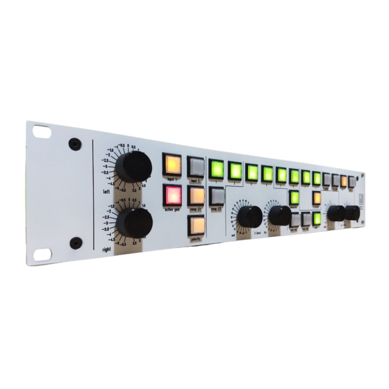
- Page 1 DuTCH.Audio IM2.3(s)
- Page 2 (middle) and to the outputs (right side), basically how the device handles signals. The IM2.3 is available in 2 versions, the IM2.2 and the IM2.3s. The only difference is the output section. More on this can be found in the output section of this manual.
- Page 3 Operation: Inputs: Input switches: On the frontpanel you can choose between the 2 inputs by pushing the corresponding switch. It’s also possible to use both inputs at the same time, but keep in mind that this will cause some impedance changes. Polarity: Above the 2 input selector switches you will find the ‘polarity switch’...
- Page 4 Simply said, the input section will go directly to the output. IM2.3 Bypass offset Out 1: Out 1 and 2 are passive output selectors with just relays, so no active circuit. So basically, it’s passing the signal from the inserts straight into the output.
- Page 5 The IM2.3(s) has two balanced inputs. Both inputs consist of gold-plated Neutrik XLR’s. Inserts: The IM2.3(s) has 8 balanced inserts connected on the back with industry standard Tascam DB25 analog connections. Each connector holds 2 inserts corresponding with the frontpanel numbering.
- Page 6 circuit based well-known circuit from Wayne Kirkwood, with additions/modifications. The internal PSU section is build around industrial-grade Meanwell SMPS’s which run way more silent and are way more efficient then old-school linear PSU’s. Both the relays/leds and active circuit PSU’s are running on their own separate PSU. When this device is used in passive mode, so without active stages, it’s 100% passive and only relay-contacts are inline.
- Page 7 The customer always pays the shipping cost to us. The customer is responsible for the product until it is delivered to us If we find that the product is flawless the customer will be charged 200 euro to cover ...
Need help?
Do you have a question about the IM2.3 and is the answer not in the manual?
Questions and answers