Advertisement
Quick Links
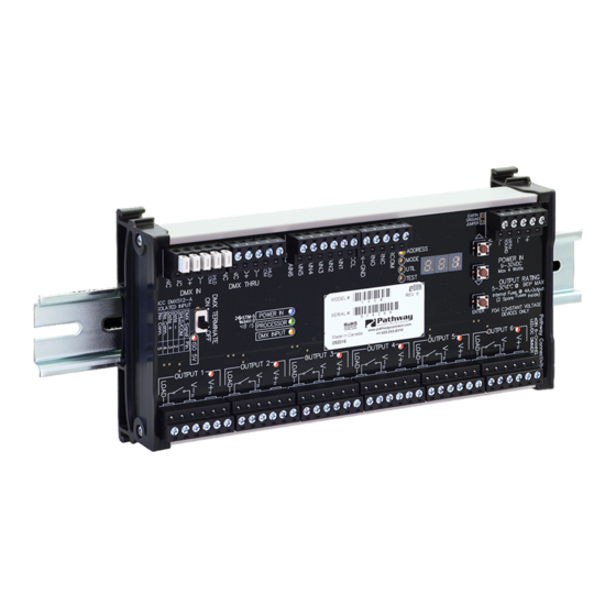
DMX Interface - PWINF DIN PWM4A / PWM6A
6-Channel PWM DC Dimmer
OVERVIEW
The Pathway eDIN LED Dimmer/DC Driver provides DMX512
control over LEDs and other DC devices. Each module
provides 6 channels of control. When controlling LEDs, the
module acts as a dimming interface only. The LED fixture
will require a separate regulated DC power supply, as
recommended by its manufacturer.
These instructions apply to REV 2 hardware running
firmware 1.6.2 or higher.
CONNECTIONS
The PWINF DIN PWM features terminal strips that can be removed
from the card to facilitate easy wiring installation or replacement. Make
the following connections, WITH THE POWER TURNED OFF, and
observe ESD precautions by ensuring the installer is properly grounded
before handling the device.
POWER
The DMX/RDM Splitter is designed to run on a range of voltages from
9-30 volts DC. Each PWM DC Dimmer requires 5 watts. Observe the
correct polarity when connecting to V+ and V-.
A second set of terminals are provided as a DC power-through
connection to other DIN devices. The EARTH GND terminal may be
connected to the enclosure's chassis or electrical ground terminal to
improve EMC compliance.
DMX512
DMX connections consist of a shield wire and one or two data pairs.
DMX IN is wired from the control console, or other source. DMX THRU
may be daisy-chained to the DMX IN of other eDIN cards, or to other
DMX equipment.
Connect DATA+ and DATA– wires to D1+ and D1- respectively. The
optional data pair may be connected to D2+ and D2-. Observe the same
polarity convention throughout the system. Connect the shield wire to
the SHLD/COM terminal.
DC/PWM OUTPUTS
The LED Dimmer/DC Driver interface provides six (6) outputs that will
each handle up to 4 amps at voltages up to 30VDC. The outputs are
of the current-sinking type. A separate DC power supply is required,
DMX In from
Control System
DMX Thru to
other DIN devices
Status LEDs
DMX IN
DMX THRU
End of line
POWER IN
PROCESSOR
DMX512
DMX INPUT
termination switch
OUTPUT 1
OUTPUT 2
1
2
3
4
5
6
1
2
3
4
5
Isolated Solid-state switch outputs (x6)
5-30VDC (External Supply Required)
4A or 6A @ 30VDC Max
Analog Inputs
(x6)
DMX Present
Contact Closure
Relay
"Panic" Input
(Normally-open,
Normally-closed,
Analog /
and Relay
Contact
common)
Input
Common
ADDRESS
MODE
UTIL
TEST
ENTER
OUTPUT 3
OUTPUT 4
OUTPUT 5
OUTPUT 6
6
1
2
3
4
5
6
1
2
3
4
5
6
1
2
3
4
5
6
1
2
3
Menu
Function LEDs
Program
pushbuttons
LED numeric
display
8.0"
[203mm]
STATUS INDICATORS
POWER IN
PROCESSOR
DMX INPUT
MENU
FUNCTION
ISO INPUT
OUTPUT
appropriately sized for the connected load, as recommended by the
connected equipment's manufacturer.
Each output is fully opto-isolated from the other outputs, from the
DMX signal and from the eDIN board power supply. Multiple pins
are provided to allow for load spreading. Outputs are connected
as follows:
LOAD- (Terminals 1 & 2): Connects to the negative terminal of
the load, or the LED Cathode.
Power In:
9-30VDC, 5W Supply required.
Use PWPWR DIN TERM [xxxx]
NOT FOR LED LOADS. Use separate
power supply for LEDs.
Connect Earth ground to improve
EMC compliance
DIN rail release lever
Use large flat-head screwdriver or
similar tool to gently pry lever
away from DIN rail to release
POWER IN
9-30VDC
Max 4 Watts
4.07"
[103.4mm]
OUTPUT RATING
5-30vdc @ 96w MAX
Internally Fused @ 4A/Output
(2 Spare Fuses Inside)
4
5
6
Blue. Glowing steadily indicates power supply OK;
off indicates no power.
Green. Glowing steadily indicates processor is
OK; off when POWER IN is lit indicates processor
failure.
Amber. Glowing steadily indicates data signal
received; off indicates no signal present.
Amber. Indicates which function is active on the
numeric display.
Red. Steady glow indicates isolated 5V supply is
OK. Off indicates no power.
Amber. Glow approximates output level.
V- (Terminals 3 & 4): Connects to
the negative or common terminal
of the load power supply.
V+ (Terminals 5 & 6): Connects
Fastening mechanism
designed for 35 X 7.5mm
to the positive terminal of the load
DIN rail
power supply and to the positive
terminal of the load, or the LED
Anode.
1.85"
[47mm]
Manual
08/31/21
Advertisement

Summary of Contents for pathway PWINF DIN PWM4A
- Page 1 DMX Interface - PWINF DIN PWM4A / PWM6A Manual 6-Channel PWM DC Dimmer OVERVIEW The Pathway eDIN LED Dimmer/DC Driver provides DMX512 control over LEDs and other DC devices. Each module provides 6 channels of control. When controlling LEDs, the module acts as a dimming interface only.
- Page 2 DMX Interface - PWINF DIN PWM4A / PWM6A Manual 6-Channel PWM DC Dimmer Mode 7: 3 Channel Mirror Mode without Curve (3 channels) DMX PRESENT RELAY CLOSURE Outputs are paired (1/4, 2/5, 3/6). Paired outputs are driven by the same DMX channel, with no compensating curve. Output follows the Wire RCOM to RNC or RNO for a normally closed or normally open DMX values linearly.
- Page 3 • Operating Conditions: 14°F-113°F (-10°C to 45°C); 5-95% relative humidity, non-condensing © 2021 Acuity Brands, Inc. • One Lithonia Way, Conyers GA 30012 Pathway Connectivity | #103 - 1439 17th Ave SE Calgary, AB Canada T2G 1J9 Phone: + 1 866 617 3074 www.pathwayconnect.com...
Need help?
Do you have a question about the PWINF DIN PWM4A and is the answer not in the manual?
Questions and answers