Advertisement
Quick Links
Advertisement

Summary of Contents for Weaver W-10KHD
- Page 1 www.derekweaver.com 817-560-9510...
- Page 2 Revised 9/19/2018 Read this entire manual before operation begins. Record below the following information which is located on the serial number data plate. Serial No. Model No. Date of Installation...
-
Page 3: Table Of Contents
Exploded View ... . 42 W-10KHD Parts List ..45 Warranty ....50... -
Page 4: Specifi Cations
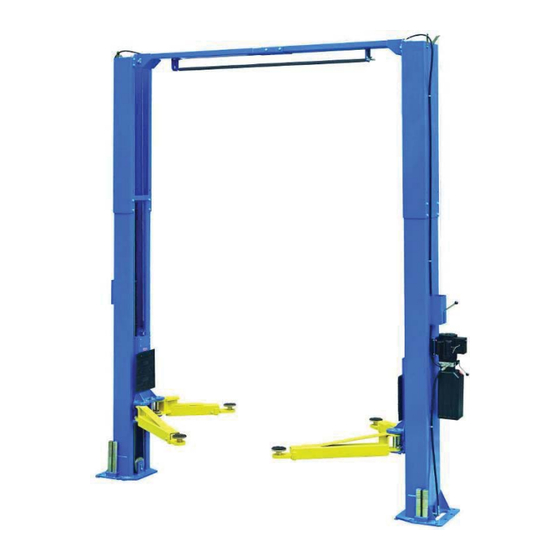
Specifi cations Clear-Floor Direct-Drive Model Features Model W-10KHD • Direct drive hydraulic cylinder design, minimizes the lift wear parts and breakdown ratio • Dual hydraulic cylinders, designed and made on ANSI standards, utilizing NOK oil seal in cylinder • Self- lubricating UHMW Polyethylene sliders and bronze bush •... - Page 5 Height Clear-fl oor 4.5 T 1842-2112mm 3635/3735mm 3492mm 2800mm 90 mm W-10KHD 3.0HP Direct drive 10,000 lbs 72 1/2”–83 1/8” 143 1/8”/ 147” 137 1/2” 110 1/4” 3 1/2” Arm Swings View For Model W-10KHD Fig. 2 W-10KHD Specifications...
-
Page 6: Installation Requirement
Screw Drivers 4 Foot Level Tape Measure (25ft) Crescent Wrench (12”) Pliers Ratchet & Socket (28mm) Allen Head Wrench (3mm, 5mm, 8mm) Wrench set (mm) Vise Grips (10#, 13#, 14#, 15#, 17#, 19#, 24#, 27#, 30#) Fig. 3 W-10KHD Installation Requirement... - Page 7 2. Concrete must be in good condition and must have a test strength 3,000psi minimum. 3. Floors must be level with no cracks or holes. Fig. 4 Power Supply 220 volt single phase motor on a 30 amp breaker with minimum of 10 gauge wire. Operating voltage range is 208v-230v. W-10KHD Installation Requirement...
-
Page 8: Installation Steps
B. Use a carpenter’s chalk line to establish installation layout of base plate Chalk Line 137.5 in Fig. 5 C. Check the parts before assembly 1. Packaged lift and hydraulic power unit. Fig. 6 W-10KHD Installation Steps... - Page 9 Fig. 8 4. Lift the upper column with a fork lift or hoist and loosen the bolts on the upper package stand. Remove the upper column and take out the parts in the bottom column. Fig. 9 W-10KHD Installation Steps...
- Page 10 5. Lift the lower column with a fork lift or hoist, remove the package stand. Remove the lower column and remove the parts in the inner column. Fig. 10 6. Move aside the parts and check the parts according to the shipment parts list. Fig. 11 W-10KHD Installation Steps...
- Page 11 7. Open the parts box and check the parts according to parts box list. Fig. 12 8. Check the parts in the parts bag 1 according to parts bag list. Bag 1 W-10KHD Fig. 13 9. Check the parts in the parts bag 2 according to parts bag list. Bag 2 W-10KHD Fig.
- Page 12 D. Install the hydraulic hose and lock release cable brackets on the extension columns. Use M6 x 20 Hex Bolts with M6 Nylock Nut & M6 Washer Fig. 15 W-10KHD Installation Steps...
- Page 14 This lift is designed with 2 sectional columns. Adjust the height according to your ceiling height. For model W-10KHD 1. When the ceiling height is less than 3750mm (147 5/8”), connect the sectional columns with the upper holes.
- Page 15 2. When the ceiling height is over 3750mm (147 5/8”), connect the sectional columns with the lower holes. Fig. 18 - High Setting W-10KHD Installation Steps...
- Page 16 G. Position posts Position the columns upright on the installation layout. Position the offside column parallel to the power side column at the approximate overall width (1371/2”). Install the overhead cross beam. Do not drill holes for anchor bolts until overhead cross beam has been installed. See Fig.
- Page 17 Then assemble the connecting bracket. Hook onto the extension columns Use M12 x 30 Hex Bolt with Self-locking Nut Fig. 23 Tighten the bolts W-10KHD Installation Steps...
- Page 18 2. Assemble overhead top beam and tighten the anchor bolts. Use M12 x 30 Hex Bolt with M12 Self-locking Nut Tighten Fig. 24 W-10KHD Installation Steps...
- Page 19 Rod for adjustment. terminal of power unit Tighten the screw after adjustment. NC: Normal Contact Connect the blue Fig. 25 wire to terminal 11# on limit switch and terminal A1 on contactor of power unit W-10KHD Installation Steps...
- Page 20 Fig. 26 - Power side safety device 145° Spring 120° Spring Use M10 x 10 Allen Head Set Screw Use M10 x 10 Hex Head Bolts to secure Fig. 27 - Offside safety device the pulley bracket W-10KHD Installation Steps...
- Page 21 K. Lift the carriages up manually and lock them on the 1st set of locks Fig. 28 W-10KHD Installation Steps...
- Page 22 L. Install cables For model W-10KHD 1. High setting cable connection. For a ceiling height over 3750mm (147 5/8”) 1.1 Remove the carriages’ plastic covers, the cable passes through from the bottom of the carriages and is pulled out from the opening of carriages, then install the two cable nuts.
- Page 23 1.2 Connecting cable for high setting. High Setting Cable 2 Cable 1 Cable 2 Fig. 30 W-10KHD Installation Steps...
- Page 24 2. Low setting cable connection. For a ceiling height less than 3750mm (147 5/8”) Low Setting Cable 2 Cable 1 Cable 2 Fig. 31 W-10KHD Installation Steps...
- Page 25 3. Special low setting cable connection W-10KHD. For a ceiling height between 3820mm (150 3/8”) to 4250mm (167 3/8”). This setting requires the optional short cables. Special Low Setting Cable 2 Cable 1 Cable 2 Fig. 35 W-10KHD Installation Steps...
- Page 26 M. Install power unit Use M8 x 25 Hex Bolts with M8 Self-locking Nut Fig. 36 W-10KHD Installation Steps...
- Page 28 Safety cable Safety cable passes through small pulley bracket Safety cable connected with the power side safety assembly Install safety cable from offside side safety assembly fi rst! Fig. 38 W-10KHD Installation Steps...
- Page 29 P. Install hose retainers on both columns Install oil hose retainers using M6 x 8 screws Car in direction Fig. 39 W-10KHD Installation Steps...
- Page 30 4. Adjust moon gear and arm lock until they mesh, then tighten the Allen bolts on the arm lock. (Fig. 43) Moon Gear Tighten the bolts after the moon gear and arm lock mesh well Arm Lock Fig. 42 Fig. 43 W-10KHD Installation Steps...
-
Page 31: Test Run
This hydraulic system is designed to bleed air by loosening the bleeding screw. Lift the carriages to about 12 inches and loosen the bleeding plug. Lower the lift until fl uid comes out. Tighten the screws after bleeding. Bleeding plug Fig. 46 W-10KHD Test Run... - Page 32 NOTE: If the lift vibrated on the way up with a load, lubricate all pulley shafts and wear blocks. If the lift vibrates on the way down, the cylinders need to be bled. Fig. 48 - Hydraulic System W-10KHD Test Run...
-
Page 33: Operation Instructions
Lower the vehicle by pushing the lowering handle; 3. Put the arms on the same side by opening the rear arms, then closing the front arms along with the rear arms; 4. Drive the vehicle away from the lift. W-10KHD Operation Instructions... -
Page 34: Maintenance Schedule
2. Check and adjust as necessary, equalizer tension of the cables to ensure level lifting; 3. Check columns for plumbness; 4. Check rubber pads and replace as necessary; 5. Check safety lock device and make sure the condition is suitable. W-10KHD Maintenance Schedule... -
Page 35: Trouble Shooting
1. Safety device are in activated 1. Release the safeties 2. Release Valve in damage 2. Repair or replace Lift will not lower 3. Safety cable broken 3. Replace 4. Oil system is jammed 4. Clean the oil system W-10KHD Trouble Shooting... - Page 37 PV10 Part# Description Item Powerside column PV10-1100A Manual Power unlt Hex Bolt M8×25 GB5780-2000-M8×25 Washerφ8 GB97.1-2002-8 GB41-2000-8 Hex Nut M8 Powerside lock cover 30500-8000-1A Main cam lock 30500-5001(B)-26G1 GB5780-2000-M12×30 Hex Bolt M12×30 Washer φ12 GB97.1-2002-12 Self locking nut M12 GB6184-2000-12 Self locking nut M6 GB6184-2000-6 GB5780-2000-M6×20...
- Page 38 Adapter 30400-6015AG Expansion bolt 3/4-10*5.5" PZ-3/4"×5.5" Rubber pad assy. PV10-4300 Bottom pulley PV10-1001 Bottom pin PV10-1200 GB5780-2000-M8×16 Hex Bolt M8×16 GB5780-2000-M10×16 Hex Bolt M10×16 Arm pin PV10-4200 Snap ring φ38 GB894.1-86-38 Washer φ10 GB97.1-2002-10 Moon gear PV10-6001 Left front arm PV10-7000DC GB70.1-2000-M10×30 Socket bolt M10×30...
- Page 39 Limit bar bracket PV10-4001 Lock washerφ10 GB93-87-10 GB41-2000-10 Hex Nut M10 Plastic ball φ35×M10 M10×SΦ35 Lock handle 30500-5001(B)-12 Large spacer 30500-5001(B)-07 Main spring 30500-5001(B)-10 Main lock HPRO-1010 GB5780-2000-M6×35 Hex Bolt M6×35 GB41-2000-6 Hex Nut M6 Small spacer 30500-5001(B)-24 Main lock pin 30500-5001(B)-09 GB78-2000-M10×16 Socket bolt M10×16...
Need help?
Do you have a question about the W-10KHD and is the answer not in the manual?
Questions and answers