Table of Contents
Advertisement
Quick Links
ELBP18TS3
FUSE
R R
R
C
R C
W
R C
W
R C
W
R C
W
R C
24Vac
1
2
1
1
1
1
CAUTION 115 VOLTS ONLY
1
2
3
4
WARNING!!!
Consult Manual Before Use
HeatLink Group Inc.
4603E - 13th Street NE
AVERTISSEMENT!!!
Calgary, Alberta, Canada
Consulter le
T2E 6M3
manual avant l'usage
Phone: (403) 250-3432
Fax: (403) 250-1155
www.heatlinkgroup.com
MODEL #: ELBP18
Serial #: XXX-XXXX
D.O.M: Nov 12, 2013
Phase/Freq: 1/60 Cycles
Max Pres: 125psi/862kPa
Max Temp: 100C/212F
Volts: 120/24 VAC
Amps: Maximum 15
Conforms to Std CAN/CSA C22.2 No. 14
Conforms to Standard UL 508
3189472
MADE IN CANADA
Any alterations to
CAUTION
electrical wiring and
controls renders warranty
null & void.
Before servicing,
disconnect power
Installation must conform
supply
to local codes. Check
valve(s) if required are the
installers responsibility.
M A D E
I N
C A N A D A
SOME UNION NUTS MAY
BECOME LOOSE
AND CONSEQUENTLY
LEAK THROUGH
TRANSPORTATION
VIBRATION AND
HANDLING. DO NOT
OVERTIGHTEN UNION NUTS
WHEN CORRECTING THIS.
DO NOT
PLUG!
PRESSURE
RELIEF
VALVE
This pipe should
be extended to
within 6 inches of
the floor by the
installer.
ELBPxxTSx Series
Installation, Operation, and Maintenance Manual
Reset
W
R C
W
R C
W
R C
W
2
2
2
2
NC NO
0
min
15
Delay
Actuator
Off
5
6
7
8
Dry Contacts
8 Zone Wired Module
40318
Pump
Boiler
ELBP50TS7
SOME UNION NUTS MAY
BECOME LOOSE
AND CONSEQUENTLY
LEAK THROUGH
TRANSPORTATION
VIBRATION AND
HANDLING. DO NOT
OVERTIGHTEN UNION NUTS
WHEN CORRECTING THIS.
WARNING!!!
HeatLink Group Inc.
Consult Manual Before Use
4603E - 13th Street NE
AVERTISSEMENT!!!
Calgary, Alberta, Canada
Consulter le
T2E 6M3
Phone: (403) 250-3432
manual avant l'usage
Fax: (403) 250-1155
www.heatlinkgroup.com
MODEL #: ELBP50TS7
Serial #: XXX-XXXX
D.O.M: Nov 12, 2013
Phase/Freq: 1/60 Cycles
Max Pres: 125psi/862kPa
Max Temp: 100C/212F
Volts: 120/24 VAC
Amps: Maximum 15
Conforms to Std CAN/CSA C22.2 No. 14
Conforms to Standard UL 508
3189472
MADE IN CANADA
DO NOT
PLUG!
PRESSURE
RELIEF
VALVE
This pipe should
be extended to
within 6 inches of
the floor by the
installer.
Any alterations to
CAUTION 115 VOLTS ONLY
CAUTION
electrical wiring and
controls renders warranty
Before servicing,
null & void.
disconnect power
Installation must conform
supply
to local codes. Check
valve(s) if required are the
installers responsibility.
M A D E
I N
C A N A D A
Advertisement
Table of Contents

Summary of Contents for Heat Link ELBP TS Series
- Page 1 ELBPxxTSx Series Installation, Operation, and Maintenance Manual ELBP18TS3 FUSE Reset 24Vac NC NO Delay CAUTION 115 VOLTS ONLY Actuator Dry Contacts 8 Zone Wired Module 40318 Pump Boiler ELBP50TS7 Any alterations to CAUTION 115 VOLTS ONLY CAUTION electrical wiring and controls renders warranty Before servicing, null &...
-
Page 2: Table Of Contents
Installation, Operation, and Maintenance Manual Table of Contents ELBPxxTSxx Product Safety Information Warnings Servicing Function Unpacking Unpacking Installation Tools Needed Panel Specifications Panel Components (Diagram) 4 Dimensions Panel Components Specifications & Listings Panel Installation Panel Mounting Piping Hookup Piping Hookup (Diagram) Fill &... -
Page 3: Product Safety Information
ELBPxxTSxx Installation, Operation, and Maintenance Manual Product Safety Information Warnings The zone control panel is for indoor use only and must be installed by a qualifi ed installer/service technician. This product must be installed and operated in strict accordance with the terms set out in this manual and in accordance with the relevant requirements of the Local Authority Having Jurisdiction. -
Page 4: Unpacking
Installation, Operation, and Maintenance Manual ELBPxxTSxx Unpacking Unpacking Examine carton for any damage that may have occurred during shipping. If damage is visible Step 1 notify your courier and supplier immediately. Open the carton by removing the staples. Step 2 Remove the cardboard spacers from the carton, then remove the panel from the carton. -
Page 5: Panel Specifications
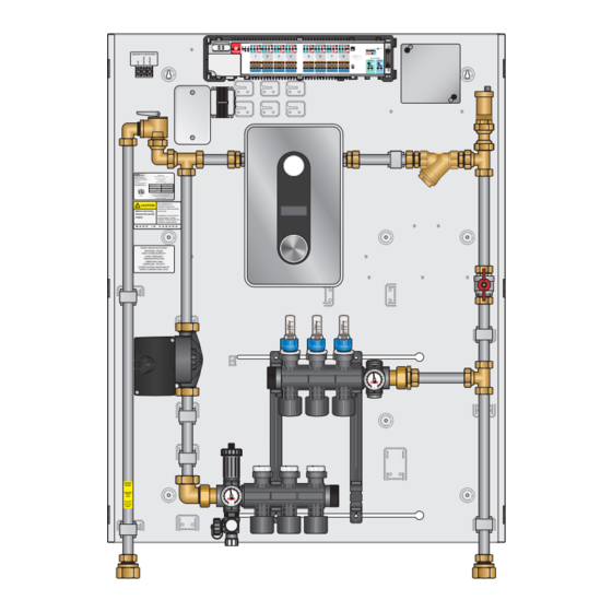
ELBPxxTSxx Installation, Operation, and Maintenance Manual Panel Specifications Panel Components (Diagram) ELBP18TS3 ELBP30TS5 FUSE Reset FUSE Reset 24Vac NC NO Delay CAUTION 115 VOLTS ONLY Actuator CAUTION 115 VOLTS ONLY 24Vac NC NO Actuator Delay Dry Contacts 8 Zone Wired Module 40318 Dry Contacts Pump... -
Page 6: Panel Components
Installation, Operation, and Maintenance Manual ELBPxxTSxx Panel Dimensions Enclosure Dimensions Stk. # Height Width Depth ELBP18 371/2” 291/4” 43/4” ELBP30 ELBP50 Panel Components Part Number (Qty.) Components Component Description ELBP18TSxx ELBP30TSxx ELBP50TSxx The electric boiler supplies hot water to the system, and is activated when Electric boiler there is a call for heat via a built in flow HA008240 (1) -
Page 7: Specifications & Listings
ELBPxxTSxx Installation, Operation, and Maintenance Manual Specifications & Listings Headings ELBP18TSxx ELBP30TSxx ELBP50TSxx Listing cETLus Conforms to CAN/CSA-C22 No.14, UL508 Dimensions 37.5" W χ 29.25" H χ 4.75" D Weight Nominal panel output 18,000 BTU 30,000 BTU 50,000 BTU Max ambient temperature 120ºF Max water temperature Settable fluid temperature range... -
Page 8: Panel Installation
Installation, Operation, and Maintenance Manual ELBPxxTSxx Panel Installation Panel Mounting Prior to mounting the panel, ensure the wall is capable of supporting the weight of the panel, and that the required 110V & 240V wiring is available at the installation location. See page xx for wiring details. The top of the panel should be a minimum of 5 feet from the floor, with sufficient space left at the bottom for required piping. -
Page 9: Piping Hookup
ELBPxxTSxx Installation, Operation, and Maintenance Manual Piping Hookup Identify the piping connections on the panel. You will need 2x 30mm, or large adjustable or Step 1 smooth jaw pipe wrenches to tighten the fittings. Ensure that the panel is mounted in the correct position Step 2 Connect the 2 adapters to the supply and return piping on the panel, using the supplied Step 3... -
Page 10: Piping Hookup (Diagram)
Installation, Operation, and Maintenance Manual ELBPxxTSxx Piping Hookup (Diagram) FUSE Reset 24Vac NC NO Delay Actuator CAUTION 115 VOLTS ONLY Dry Contacts 8 Zone Wired Module 40318 Pump Boiler WARNING!!! Consult Manual Before Use HeatLink Group Inc. 4603E - 13th Street NE AVERTISSEMENT!!! Calgary, Alberta, Canada Consulter le... -
Page 11: Fill & Purge
ELBPxxTSxx Installation, Operation, and Maintenance Manual Fill & Purge The following steps are recommended in order to fill the panel with water and purge entrained aironce piping is completed, and before activation of the panel. Note: Additional purging steps may be required for the rest of the system. CAUTION Any alterations to CAUTION 115 VOLTS ONLY... - Page 12 Installation, Operation, and Maintenance Manual ELBPxxTSxx Step 12 Once each loop has been filled, close all supply and return manifold valves. Step 13 Open valves F, G, H. Step 14 Watch the purge hose in the pail until you observe a steady stream of water (no air or spitting). Any alterations to CAUTION 115 VOLTS ONLY CAUTION...
- Page 13 ELBPxxTSxx Installation, Operation, and Maintenance Manual Thermostat & Actuator Wiring Step 1 Remove the plastic cover. Open (and close) the four white screws with a quarter turn only. Note that screws on opposite sides turn in the opposite FUSE Reset direction.
- Page 14 Installation, Operation, and Maintenance Manual ELBPxxTSxx Step 6 Bend over and push all thermostat wires into the round holes at the top of the module. FUSE 24Vac FUSE 24Vac FUSE 24Vac Step 7 Push the actuator wires into the round holes at the bottom of the module.
-
Page 15: Panel Control Sequence & Wiring
ELBPxxTSxx Installation, Operation, and Maintenance Manual Panel Control Sequence & Wiring Two (2) Double Pole 50 Amp circuit breakers must be installed in the main electrical panel. All wiring should be done by a qualified electrician, and should meet local codes and jurisdictions. HeatLink®... -
Page 16: Troubleshooting
Installation, Operation, and Maintenance Manual ELBPxxTSxx Troubleshooting Problem Check / Verify Possible Cause Low temperature within room Misplacement of thermostat location within Make sure thermostat is not being influenced by an room. additional heat source, such as lighting or air duct. Low temperature setting of the thermostat. - Page 19 Installation, Operation, and Maintenance Manual ELBPxxTSxx www.heatlink.com...
- Page 20 August 23, 2022 Printed in Canada ©HeatLink Group Inc.
Need help?
Do you have a question about the ELBP TS Series and is the answer not in the manual?
Questions and answers