
Subscribe to Our Youtube Channel
Summary of Contents for GCC Technologies LFC
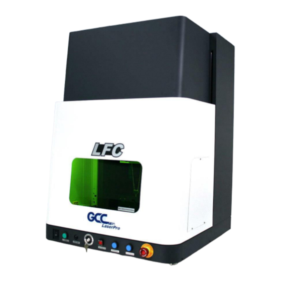
- Page 1 LFC Desktop Workstation User Manual Version: 2.0 Release 2021 4F., No.236, Fude 2nd Rd., Xizhi Dist., New Taipei City 22151, Taiwan 886-2-6616-6692 Fax:886-2-2694-6875...
- Page 2 Release Note Version Release Date Change Apr, 2020 First Version Aug, 2021 Add marker installation instruction LFC-D Workstation User Manual...
-
Page 3: Table Of Contents
Software Installation for Windows System ............34 Software Installation for MAC System ..............39 Setting User Level .....................47 Chapter 6 Operating the LFC Desktop Workstation ........54 Hardware Introduction .....................55 LFC Desktop Workstation Service Mode Operation ........57 LFC Desktop Workstation OP Mode Operation ..........59 Chapter 7 External Control ................ -
Page 4: Chapter 1 Safety
Chapter Safety Safety Ratings Safety Label The Safety Interlock System Safety Measures Operating Environment LFC-D Workstation User Manual... -
Page 5: Principles Of Co2 Laser
One of the key safety features found on the LFC Series workstation is Class 2 red dot safety guidance pointers allowing users to see where the laser beam is travelling and helping find out the precise focus point for laser to do quality job. -
Page 6: The Safety Interlock System
1.4 The Safety Interlock System The LFC Series Workstation is equipped with a safety interlock system utilizing limit switch sensors on the electronically controlled front door. The limit switch sensor will shut the laser off when detecting front door open. Do not attempt to remove or modify these limit switches or any other component of the safety interlock system. - Page 7 Product Label This label is located at the rear right side of LFC Series Workstation. All the product information such as Serial Number, Model Name, Electric power and Input can be found here. Before requiring any tech support, always provide service person the information on this label.
- Page 8 CE Label This label identifies the classification of the Model in accordance with IEC 60825-1. It is located on the rear of the LFC Series Workstation. Emergency Stop Label This label indicates the emergency stop button. You can find this label on the right side of LFC Series Workstation front button operation section.
- Page 9 Warning Label Warning Label is written with all the necessary information to be aware of during machine operation. Door open warning labels Labels are located on the machine’s cabinet doors, machine becomes Class 4 when doors open. LFC-D Workstation User Manual...
-
Page 10: Safety Measures
• Resulting debris from laser cutting are very dangerous and may cause fire hazard. • Always wear safety goggles when the GCC LFC Series is in operation. Reflective materials such as mirrors, enameled brass and anodized aluminum may partially-reflect some of the invisible laser radiation. -
Page 11: Operating
1.7 Operating Please follow the guidelines when considering a suitable location to set the GCC LFC Series. Improper work environments may lead to operational malfunction and/or unsafe working conditions. The GCC LFC Series should be placed and operated in a clean... -
Page 12: Chapter 2 Unpacking & Content
Chapter Unpacking & Content Unloading & Unpacking Contents & Accessories checklist LFC-D Workstation User Manual... -
Page 13: Contents & Accessories Checklist
2.1 Contents & Accessories Checklist The GCC LaserPro LFC Series Workstation is shipped in one crate that contains machine, software, and all of the necessary accessories. The following section shows detailed step-by- step instructions for unpacking and assembly the accessory to workstation. - Page 14 Step 3. Untie the knot. Step 4. Unbuckle and remove the two safety harnesses that hold the machine in place. LFC-D Workstation User Manual...
- Page 15 Step 5. Move the machine and placed on a stable desktop. LFC-D Workstation User Manual...
-
Page 16: Contents & Accessories Checklist
Please check to make sure that all the following items are included within the shipping crate. If any of the following items are missing, immediately contact your local GCC representatives. GCC LaserPro LFC-D Workstation Checklist Name Unit LaserPro CD set (User's Manual) - Page 17 Laser Head Power Cable (2.5M) SCSI Cable 50pin (2.5M) AC Power Cable(Europe) AC Power Cable (US) AC Power cable (Australian) USB Cable 1.8M GCC Promise Card Set 4 Port PCI USB 2.0 card StellarMark Accessories checklist LFC-D Workstation User Manual...
- Page 18 Software Keypro for G-Mark Advance Lens Cleaner Lens Cleaning Paper Cotton Bud (100pcs/ pack) 1064nm Goggle Lens parameter Card M6 screw plastic foot Nut (M6xt5xS10). I/O Terminal Platform(5ESDVM-10P) I/O Terminal Cable 25 pin Hex head screws driver Warranty Card LFC-D Workstation User Manual...
-
Page 19: Chapter 3 Mechanical Overview
Chapter Mechanical Overview Front View Right View Left View Rear View LFC-D Workstation User Manual... -
Page 20: Front View
3.1 Front View Z-axis Up and Down Button Start Button Key Switch Fiber Laser Emergency Stop LED Light Main Power ON Button Button Switch LFC-D Workstation User Manual... -
Page 21: Right View
3.2 Right View 3.3 Left View LFC-D Workstation User Manual... -
Page 22: Rear View
3.4 Rear View External Signal Indicator I-Series I/O Connector C-Series I/O Connector Laser Marker Power I/O Terminal Connector Rotary Attachment Connector Power Cable Inlet LFC Port Connector Ventilation Openings Pass-Through Door Switch Port LFC-D Workstation User Manual... -
Page 23: Chapter 4 Machine Installation
Chapter Machine Installation Laser Marker Installation LFC-D Workstation User Manual... -
Page 24: Laser Marker Installation
4.1 Laser Marker Installation Step 1. Plug in the power cable on the back of the LFC D Step 2. Turn on the power of the LFC D LFC-D Workstation User Manual... - Page 25 Step 3. Turn the key switch to the “Operation” mode Step 4. Press on “Z-axis Down” button to down the Z-axis to the lowest position LFC-D Workstation User Manual...
- Page 26 Step 5. Loosen 2 screws to remove the cable cover of LFC Desktop Workstation Step 6. Loosen 4 screws to remove the back cover of LFC Desktop Workstation LFC-D Workstation User Manual...
- Page 27 Step 7. Put the laser marker into the LFC-D from the back side Step 8. Take out the “Marker Installation Tool” from the accessory kit (The tool is depends on your laser marker model) LFC-D Workstation User Manual...
- Page 28 Step 9. Put the tool on the Z-axis Step 10. Align laser marker to the installation tool to ensure the screws can be fixed with ease LFC-D Workstation User Manual...
- Page 29 Step 11. Press on “Z-axis Up” button to raise the z-axis to the highest position Step 12. Tighten 4 screws from the bottom of z-axis to fix the laser maker on the LFC D LFC-D Workstation User Manual...
- Page 30 Step 13. Please perform the following steps to connect cables. For CIIS / IFIIS 1) Connect the laser marker power cable and SCSI cable to the control unit according to your model. LFC-D Workstation User Manual...
- Page 31 2) Connect the laser marker power cable and SCSI cable to the laser marker according to your model. 3) Connect the power cord between the control unit and LFC Desktop Workstation. LFC-D Workstation User Manual...
- Page 32 4) Connect the I/O cable between the control unit and LFC Desktop Workstation. 5) For IFII/IFIIS series, please connect the LFC port cable between the control unit and LFC Desktop Workstation. LFC-D Workstation User Manual...
- Page 33 6) Connect the USB cable between the control unit and computer / Laptop. 7) Plug the G-Mark software keypro to the computer / laptop’s USB port. LFC-D Workstation User Manual...
- Page 34 For 3DS 1) Connect the power cord between the 3DS and LFC Desktop Workstation. 2) Connect the I-series I/O Connector cable between the 3DS and LFC D. 3) Connect the power cord of LFC Desktop Workstation. LFC-D Workstation User Manual...
- Page 35 Step 14. Assemble the back cover on the LFC Desktop Workstation. Step 15. Assemble the cable cover. Step 16. Installation is completed. LFC-D Workstation User Manual...
-
Page 36: Chapter 5 Software Setup
Chapter Software Setup Recommended Computer Configuration Software Installation for Windows System Software Installation for MAC System Setting the User Level LFC-D Workstation User Manual... -
Page 37: Recommended Computer Configuration
ROM drive of PC. Step 2. Wait few seconds for the CD Manager to begin the Setup automatically Step 3. Click on “for LFC Workstation” from the menu of the G-Mark installation CD according to your operating system LFC-D Workstation User Manual... - Page 38 Step 4. Set the destination directory and click "Next>" Step 5. Select "Next>" Step 6. Installing LFC-D Workstation User Manual...
- Page 39 Step 7. At 95% completion of the installation, the ModelManger window will show up. Step 8. Select the laser marker series & model type. LFC-D Workstation User Manual...
- Page 40 Step 9. Click “OK” LFC-D Workstation User Manual...
- Page 41 StellarMark laser marking system. Step 12. Import or Open a new G-Mark graphic file to start the graphic design and setup the laser parameters for output. LFC-D Workstation User Manual...
-
Page 42: Software Installation For Mac System
Windows OS in MAC computers and run Windows based software under MAC computer and output with G-Mark. Step 1. Purchase Parallels Desktops on its official website. Step 2. Install Parallels Desktops under Mac OS environment. LFC-D Workstation User Manual... - Page 43 Step 3. Read Software License Agreement and press “Accept” to continue installation Step 4. Enter your Mac OS X User Name and Password then press “OK” LFC-D Workstation User Manual...
- Page 44 Step 5. Press “Active” Step 6. Press “OK” when activation is complete. LFC-D Workstation User Manual...
- Page 45 Step 7. Register Parallels Desktop Step 8. Press “Register” and “OK” to complete the installation of Parallels Desktop. LFC-D Workstation User Manual...
- Page 46 Step 9. Open Parallels Desktop (in the Applications folder) then choose File → Step 10. Press “Install Windows from DVD or image file” then press “continue” to install windows OS LFC-D Workstation User Manual...
- Page 47 Step 11. Select CD-ROM drive with the Windows installation CD Step 12. Enter the Windows OS product key LFC-D Workstation User Manual...
- Page 48 Step 13. Select how you would like to run your Windows program. Step 14. After the prior setting is complete the windows OS installation procedure will start automatically. LFC-D Workstation User Manual...
- Page 49 Once the G-Mark software installation is completed, you can start to open a new file to edit or import an existing file to G-Mark for laser processing. For G-Mark software operation manual, you can refer to “G-Mark software user manual” in the StellarMark CD from accessory box. LFC-D Workstation User Manual...
-
Page 50: Setting User Level
Programmer can edit objects and use some limited functions. Administrator Administrator can use all G-Mark functions and has authority to change the system setting. Such as change password or authorize software function for each user level. LFC-D Workstation User Manual... - Page 51 5.3.1 Switch User Level Select “Execute” → “User Level” from menu bar Step 1. Select user level and input password Step 2. LFC-D Workstation User Manual...
- Page 52 Password is protected in Programmer & Administrator user levels. ⚫ Default password for Programmer & administrator levels is “stellarmark”. 5.3.2 Modify Password The following steps illustrate how to modify user level password Step 1. Select “Execute” → “User Level” from menu bar LFC-D Workstation User Manual...
- Page 53 Step 2. Select “Administrator Level” and input password. Step 3. Click on “Modify Password” and the modify password window will show up. Step 4. Input the new password for programmer level or administrator level. LFC-D Workstation User Manual...
- Page 54 5.3.3 Purview Setting Purview setting only for administrator level, administrator can enable/disable software function for programmer and operator level. The following steps illustrate how to setting the purview Step 1. Select “Execute” → “User Level” from menu bar LFC-D Workstation User Manual...
- Page 55 Step 2. Select “Administrator Level” and input password Step 3. Click on “Purview Setting” button and the Purview Setting window will pop up. Step 4. Click “Category” list to set all the software function LFC-D Workstation User Manual...
- Page 56 Step 5. All the software function can be authorized or unauthorized in the purview setting; select checkboxes allow you to activate a function for different user level and vice versa. Step 6. Click on “Exit” button after the setup is complete. LFC-D Workstation User Manual...
-
Page 57: Chapter 6 Operating The Lfc Desktop Workstation
Chapter Operating the LFC Desktop Workstation Hardware Introduction Service Mode Operation OP Mode Operation LFC-D Workstation User Manual... -
Page 58: Hardware Introduction
6.1 Hardware Introduction 6.1.1 Emergency Stop Button Press the Emergency Stop button to stop the AC power of the LFC desktop workstation for emergency. To reset this button, rotate clockwise. NOTE Please turn off the mater power of machine and reset emergency stop button then re-start the machine and G-Mark software after pressing the emergency stop button. - Page 59 6.1.4 LED Light Switch Switch the LED light ON or OFF. 6.1.5 Fiber Laser ON Button The fiber laser ON button only for StellarMark IF series, always turn ON to allow fiber laser firing. LFC-D Workstation User Manual...
-
Page 60: Lfc Desktop Workstation Service Mode Operation
6.1.6 Main Power ON/OFF Switch Switch the AC Power ON/OFF of the LFC desktop workstation. 6.2 LFC Desktop Workstation Service Mode Operation Step 1. Turn on the machine. Step 2. Turn the key switch to service mode, and then the door will open automatically if door is closed. - Page 61 Step 6. After editing, click “Marking” button, and then the “Marking” window will pop up. Step 7. Click “Exec” button from G-Mark marking software to starting the job. NOTE The auto door will always open in the service mode, please ware goggle to operate the machine. Step 8. Job complete. LFC-D Workstation User Manual...
-
Page 62: Lfc Desktop Workstation Op Mode Operation
6.3 LFC Desktop Workstation OP Mode Operation Step 1. Turn on the machine. Step 2. Turn the key switch to OP mode, and then the door will open automatically if door is closed. NOTE Please switch the user level to “Operator level” on G-Mark marking software after turn the key switch to OP mode to avoid any abnormal. - Page 63 Step 6. After editing, click “Marking” button, and then the “Marking” window will pop up. Step 7. Click “Exec” button from G-Mark marking software to starting the job. NOTE The auto door will always open in the service mode, please ware goggle to operate the machine. LFC-D Workstation User Manual...
- Page 64 Step 8. When the job starts, the door will close automatically, and then laser firing. Step 9. Job complete. LFC-D Workstation User Manual...
-
Page 65: Chapter 7 External Control
Chapter External Control I/O Pin Assignments Laser Working Flow Chart Laser Reaction Timing Diagram LFC-D Workstation User Manual... -
Page 66: I/O Pin Assignments
7.1 I/O Pin Assignments The I/O terminal connector is located on the bottom rear of LFC workstation, and the definition corresponding with the input and output signals on the G-Mark software as follows. TYPE DESRIPTION There are 2 input signals (External device → LFC) - Page 67 (2) Output pins Not Available The pin 1~4 & pin 7~16 from Output status are not available to communicate with laser marker. NOTE High / Low definitions in G-Mark software LFC-D Workstation User Manual...
-
Page 68: Laser Working Flow Chart
Ready signal is OFF when laser is firing Job is completed G~H it will take about less than < 1µ sec. for the external device to receive a “Ready” signal from the laser marker G-Mark marking software is closed Power off LFC-D Workstation User Manual... -
Page 69: Laser Reaction Timing Diagram
◆ Laser Signal Output → External Device Delaying Time It takes about X < 1µ sec for the external device to receive an output signal from the laser marker. → DELAY OUTPUT USER RECEIVED μ X < 1 LFC-D Workstation User Manual... - Page 70 ◆ External Device Output Signal →Laser Firing Delaying Time It takes about 10 µ sec < X < 20 µ sec for the laser marker to receive an input signal from the external device → DELAY INPUT LASER WORKING LFC-D Workstation User Manual...
-
Page 71: Chapter 8 Basic Maintenance
Chapter Basic Maintenance Regular Spot Check Cleaning the Scan Lens LFC-D Workstation User Manual... -
Page 72: Regular Spot Check
This section will cover how to perform regular maintenance for the scan lean of LFC Series Workstation. The frequency of the cleaning schedule will depend on number of variables such as the types of material you work with, the immediate work environment, the frequency of use, the quality of the exhaust system, etc. - Page 73 The vapour is heavier than air and may spread long distances making distant ignition and flashback possible. NOTE Never touch the scan lens with your bare hand. The oils from your hand will distort the laser beam passing through the lens. Use finger cots or rubber gloves when cleaning. LFC-D Workstation User Manual...
-
Page 74: Chapter 9 Appendix
Chapter Appendix LFC-D Workstation Specification LFC-D Workstation User Manual... - Page 75 AC Auto Switching 115 / 230V, 50-60Hz / Single Phase Power Consumption 1240W Operating Temperature 15C~35C Operating Humidity 10 ~ 80% Non-condensing Dimension 94(L) x 102(W) x 147(H) N.W. 100 kg G.W. 180 kg Rotary Attachment Optional Items MultiFOCUS Air Extraction System LFC-D Workstation User Manual...
Need help?
Do you have a question about the LFC and is the answer not in the manual?
Questions and answers