Table of Contents
Advertisement
Quick Links
Advertisement
Table of Contents

Related Manuals for Riken Keiki PT9E-0137


Summary of Contents for Riken Keiki PT9E-0137
- Page 1 PT9E-0137 RP-2009 Pump for the GX-2009 Operating Manual...
- Page 2 Safety Information The pump unit RP‐2009 is gas suction pump and suctioned gas will be transfer to the GX‐2009.GX‐2009 is a diffusion type of the Gas Monitor, but it can be used as a suction type by connecting with RP‐2009. The sample gas is sucked by build‐in micro pump. The applicable battery is alkaline dry battery. Specification for safety ・Ex ia IIC T4 Ga ・Ambient temperature range for use : ‐20°C to +50°C Electrical data ・Powered by an AA size alkaline battery, model LR6 by TOSHIBA. Certificate numbers ・IECEx Certificate number : IECEx DEK 12.0066 ・ATEX Certificate number : DEKRA 12ATEX0209 List of standards ・IEC 60079‐0:2017 ・EN IEC 60079‐0:2018 ・IEC 60079‐11:2011 ・EN60079‐11:2012 WARNING ・Do not replace dry battery in hazardous location. ・Do not attempt to disassemble or alter the instrument. ・Use only with connected Alkaline AA battery, type LR6 manufactured by Toshiba. INST. No. 0 0 0 0 0 0 0 0 0 0 0 A B C D E A: Manufacturing year (0‐9) B: Manufacturing month (1‐9,XYZ for Oct.‐Dec.) C: Manufacturing lot D: Serial number E: Code of factory RP-2009 Pump for the GX-2009 ...
- Page 3 Product Warranty RIKEN KEIKI. warranties gas alarm equipment sold by us to be free from defects in materials, workmanship, and performance for a period of one year from date of shipment from RIKEN KEIKI. Any parts found defective within that period will be repaired or replaced, at our option, free of charge. This warranty does not apply to those items which by their nature are subject to deterioration or consumption in normal service, and which must be cleaned, repaired, or replaced on a routine basis. Examples of such items are: a) Absorbent cartridges d) Batteries b) Pump diaphragms and valves e) Filter elements c) Fuses Warranty is voided by abuse including mechanical damage, alteration, rough handling, or repair procedures not in accordance with the operator’s manual. This warranty indicates the full extent of our liability, and we are not responsible for removal or replacement costs, local repair costs, transportation costs, or contingent expenses incurred without our prior approval. THIS WARRANTY IS EXPRESSLY IN LIEU OF ANY AND ALL OTHER WARRANTIES AND REPRESENTATIONS, EXPRESSED OR IMPLIED, AND ALL OTHER OBLIGATIONS OR LIABILITIES ON THE PART OF RIKEN KEIKI., INCLUDING BUT NOT LIMITED TO, THE ...
-
Page 4: Table Of Contents
Table of Contents Overview .................... 1 Specifications .................. 1 Description .................... 2 Pump Unit .................... 3 Rubber Sample Nipple ................ 4 Optional Hose & Probe ................ 4 Operation .................... 5 Normal Operation .................. 5 Low Flow Alarm .................. 11 Maintenance .................. 1 2 Replacing the Battery ................ 12 Replacing the Cotton Dust Filter ............ 12 Replacing the Hydrophobic Disk Filter and Wire Mesh Disk ..... 13 Parts List .................... 1 4 WARNING: Understand manual before operating and for proper battery type. -
Page 5: Overview
Overview This manual describes the RP‐2009 pump. This manual also describes how to operate the RP‐2009 with the GX‐2009 and how to maintain the RP‐2009. A parts list at the end of this manual lists replacement parts and accessories for the RP‐2009. Specifications Table 1 lists specifications for the RP‐2009 pump. Table 1: Specifications Power Supply 1 ea. AA size alkaline Operating Time 8 hours minimum at 25°C Operating -20°C to +50°C, 0 - 85% Relative Humidity (non-condensing) Temperature & Humidity Dimensions 33 (D) x 57 (W) x 142 (H) mm, tapered nozzle not included Weight Approximately 123 g (including alkaline battery) -
Page 6: Description
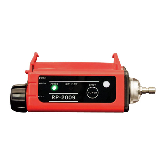
Description The RP‐2009 pump is a sample drawing accessory for the GX‐2009 Gas Monitor. It consists of the pump unit and the rubber sample nipple. Sensor Adapter Power LED Low Flow LED Filter Holder Instrument Power Button Release Indicator Rubber Sample Nipple O PEN RELEASE POWER LO W FLOW RESET POW ER RP-2009 LOCK Pump Unit Instrument Lock Indicator Front Inlet Fitting (GX-7 Type) Instrument Retaining Clips Release Tab... -
Page 7: Pump Unit
Pump Unit The pump unit is housed in a red plastic case. A GX‐7 type male quick connect fitting is located on one end of the pump unit. This is the inlet fitting to the pump unit. The GX‐7 quick connect is installed in a removable clear plastic filter holder. A cotton dust filter is inside the filter holder. The filter holder may be removed by turning it counterclockwise and pulling it away from the pump unit. Two flat membrane disk hydrophobic filters and a wire mesh disk are located in the pump unit on the filter holder end. The battery compartment is located on the other end of the pump unit. One AA alkaline battery is installed in the battery compartment and held in place by a black plastic battery cap. The battery cap may be removed for access to the battery by pushing it down, turning it 1 / 4 turn counterclockwise, and pulling it away from the pump unit. The exhaust fitting is located under the battery cap tab. A POWER button, a power indication LED, and a low flow LED are located along the middle front of the pump unit. The power LED is on when the pump unit is on. The low flow LED flashes when the pump is experiencing a low flow condition. An instrument release indicator and an instrument lock indicator are located on the front left of the pump unit. The indicator tab on the battery cap indicates the current position of ... -
Page 8: Rubber Sample Nipple
gasket. Rubber Sample Nipple A cone shaped 4 inch long rubber sample nipple is included with the RP‐2009 and is normally installed on the inlet fitting by pushing the larger end over it. The smaller end can be inserted in a hole or some other access to an enclosed area to sample the environment. Optional Hose & Probe When desired, the rubber sample nipple may be removed and a sample hose and probe with GX‐7 fittings (optional accessories) may be connected to the inlet fitting. Sample hose lengths are available from 10 feet to 30 feet (see Parts List at the end of the manual). CAUTION: Sample hose lengths of more than 30 feet are not recommended for the RP‐2009 because of flow rate reduction. RP-2009 Pump for the GX-2009 ... -
Page 9: Operation
Operation Normal Operation 1. Start up the GX‐2009 and enter normal operation as described in the GX‐2009 Operator’s Manual. 2. Push down on the RP‐2009’s battery cap and rotate it 1 / 8 turn counterclockwise so that the indicator tab on the battery cap is next to “RELEASE”. Indicator Tab "RELEASE" Figure 2: Releasing the Battery Cap WARNING: Do not install the GX-2009 onto the RP-2009 without rotating the battery cap to “RELEASE”. Installing the GX-2009 onto the RP-2009 with the battery cap in the “LOCK”... - Page 10 until the GX‐2009 is seated in the RP‐2009 and the retaining clips are fully engaged with the GX‐2009. Be sure that the RP‐ 2009 is fully engaged on the instrument. When fully engaged, the GX‐2009 should not move around at all. CAUTION: If the RP‐2009 is not fully engaged, the unit will not respond to the target gases properly. %LEL POWER RP-2009 Indicator Tab Figure 3: Connecting the RP‐2009 to the GX‐2009 ...
- Page 11 5. Secure the GX‐2009 in the RP‐2009 by pushing down on the battery cap and rotating it an 1 / 8 turn clockwise so that the indicator tab on the battery cap is next to “LOCK”. Indicator Tab PUSH "LOCK" Figure 4: Locking the Battery Cap RP-2009 Pump for the GX-2009 ...
- Page 12 6. Attach the rubber sample nipple or an optional hose and probe to the inlet fitting. OPEN POWER LOW FLOW RESET Figure 5: Connecting the Optional Hose & Probe 7. Attach the RP‐2009 / GX‐2009 assembly to your belt or clothing using the belt clip on the GX‐2009. 8. Turn on the pump unit by pressing and holding the POWER button until the RP‐2009 beeps and the power indication LED turns green, about 2 seconds. WARNING: While the GX‐2009 is installed in the RP‐2009, the pump must be on for the GX‐2009 to function as a gas detection monitor. 9. Go to the area to be sampled. If the rubber sample nipple is used, detach the RP‐2009 / GX‐ 2009 assembly from your belt and hold the RP‐2009 / GX‐2009 assembly near the area to by sampled. If sampling from a vessel or an enclosed area is desired, insert the rubber sample nipple into the vessel or enclosed area. Allow the pump unit to sample for 90 seconds for a full response on the GX‐2009. RP-2009 Pump for the GX-2009 ...
- Page 13 If an optional hose and probe are used instead of the rubber sample nipple, hold the probe in the area to be sampled. To sample from a well or other similar sample area, the hose and probe may be lowered into the sample area. Allow the pump unit to sample for 90 seconds for a full response on the GX‐2009. NOTE: Although the RP‐2009 pump does have a hydrophobic filter built in, the optional probe does not have a hydrophobic filter. It has a dust filter only. 10. Monitor the GX‐2009 display for the gas readings and take appropriate action if gas alarms occur. 11. When sampling is complete, go to a fresh air area and turn off the pump unit. 12. Remove the RP‐2009 / GX‐2009 assembly from your belt or clothing. 13. Turn off the RP‐2009 by pressing and holding the POWER button until the RP‐2009 sounds a long beep and the power indicator LED turns off, about 3 seconds. 14. Turn off the GX‐2009. RP-2009 Pump for the GX-2009 ...
- Page 14 15. To remove the GX‐2009 from the RP‐2009, push down on the battery cap and rotate it an 1 / 8 turn counterclockwise so that the indicator tab on the battery cap is next to “RELEASE”. Indicator Tab "RELEASE" Figure 6: Releasing the Battery Cap WARNING: Do not remove the GX-2009 from the RP-2009 without rotating the battery cap to “RELEASE”. Removing the GX-2009 from the RP-2009 with the battery cap in the “LOCK”...
-
Page 15: Low Flow Alarm
16. Press the bottom of the release tab toward the pump unit and pull up on the GX‐2009. GX-2009 POWER Release Tab MODE %LEL Indicator Tab OPEN RELEASE POWER LOW FLOW RESET POWER RP-2009 LOCK Figure 7: GX‐2009 Removal Low Flow Alarm When pump unit experiences a low flow condition, the low flow LED starts flashing and the pump stops operating. Check the rubber sample nipple and filters to make sure they are clear. If a hose and probe are used, check them for kinks or obstructions. To reset the low flow condition, press and release the POWER button. If the low flow condition persists, the pump may need ... -
Page 16: Maintenance
Maintenance Replacing The Battery 1. Locate the black plastic battery cap on one end of the pump unit. 2. Push down and rotate battery cap counterclockwise until it stops, 1 / 4 of a turn. 3. Pull the battery cap away from the pump unit. 4. Remove the old battery from the pump unit. It will slide right out. 5. Insert the new battery + end first into the pump unit. Use an AA alkaline. The battery orientation is shown on the bottom of the pump unit. 6. Slide the battery cap over the battery onto the pump unit, push it down and turn it clockwise unit is stops beneath the instrument release tab. Replacing the Cotton Dust Filter 1. Locate the clear plastic filter holder at one end of the pump unit. 2. Grasp the ridged sides of the filter holder and turn it 1 / 4 of a turn counterclockwise. ... -
Page 17: Replacing The Hydrophobic Disk Filter And Wire Mesh Disk
Replacing the Hydrophobic Disk Filter and Wire Mesh Disk 1. Locate the clear plastic filter holder at one end of the pump unit. 2. Grasp the ridged sides of the filter holder and turn it 1 / 4 of a turn counterclockwise. 3. Pull the filter holder away from the pump unit. Do not lose the cotton dust filter. 4. The hydrophobic disk filters and wire mesh disk are located in the pump unit and are retained by a rubber gasket. Pull out the rubber gasket with needle nose pliers. Hydrophobic Disk Filter Rubber Gasket Cotton Dust Filter Installation Filter Holder Wire Mesh Disk Stub OPEN RELEASE... -
Page 18: Parts List
the wire mesh disk. 7. Reinstall the gasket with the parts into the pump unit. 8. Reinstall the filter holder with the cotton dust filter. Align the two tabs on the bottom of the filter holder with the two slots in the pump unit. Push the filter holder into the pump unit and turn it 1 / 4 turn clockwise until it snaps into place. Parts List Table 2 lists replacement parts and accessories for the RP‐2009 pump. Table 2: Parts List Part Number Description 4181-5430-10 Gasket, filter/screen retaining 1410-3200-10 O-ring, for battery compartment 0888-0347-90 Tapered rubber nozzle 4775-9945-00 Filter case assy, clear plastic 4181-9610-90 Battery cap... - Page 19 ...
Need help?
Do you have a question about the PT9E-0137 and is the answer not in the manual?
Questions and answers