
Related Manuals for Besantek BST-CT105

Summary of Contents for Besantek BST-CT105
- Page 1 BESANTEK BST-CT105 Amplifier Probe & Tone Generator INSTRUCTION MANUAL 99 Washington Street Melrose, MA 02176 Phone 781-665-1400 Toll Free 1-800-517-8431 Visit us at www.TestEquipmentDepot.com BESANTEK CANADA Corporation,...
-
Page 2: Table Of Contents
Index Page AMPLIFIER PROBE....... FEATURES........... INSTRUCTIONS........MAINTENANCE........TONE GENERATOR....... FEATURES........... INSTRUCTIONS........MAINTENANCE........ -
Page 3: Amplifier Probe
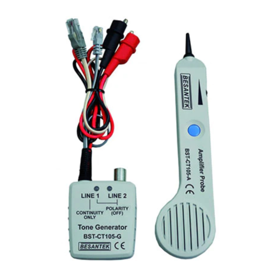
BESANTEK AMPLIFIER PROBE Figure 2 FEATURES • The Amplifier Probe is designed to identify and trace wires or cables within a group without damaging the insulation. • Works with any Tone Generator to identify wires. • Volume control for increased sensitivity and adjustable to suit work environment. -
Page 4: Instructions
INSTRUCTIONS ● Connecting the tone generator. In terminated working cables : Connect one test lead to a terminated wire and the other test lead to earth or equipment ground.(See figure 2) In unterminated or non-working cables : Connect one test lead to an unterminated wire and the other test lead to another unterminated wire. -
Page 5: Tone Generator
BESANTEK TONE GENERATOR BST-CT105--G limiiil"CE Figure 3 - -" Figure 4 .. e •• BESANTEK Corporation, CANADA... -
Page 6: Features
FEATURES ● Red and black test leads with a standard 4 conductor modular cord and plug. ● A 3-position toggle switch controls the modes of operation and two bi-colored LEDs display line polarity for Lines 1 and 2. ● The tone and continuity (cont.) test functions are only applied to Line 1 using the modular plug. -
Page 7: Instructions
INSTRUCTIONS All of the following tests can be performed by using the red and black test leads or the modular plug. NOTE : When using the modular test plug, the polarity test function applies to Lines 1 and 2. The continuity and tone functions ONLY apply to Line 1. - Page 8 ● Verifying lines (switch to "off" then "cont") 1. Dial the line to be verified. 2. While the line is ringing, connect the RED lead to the RING SIDE of the line and the BLACK to the TIP. 3. In the "OFF" position, the indicator lamp will flicker "RED and GREEN"...
- Page 9 ● Testing continuity (switch to "cont") CAUTION : DO NOT CONNECT TO ANY ACTIVE AC OR DC CIRCUIT IN THIS MODE. 1. Connect the test leads to the subject pair. 2. Use "cont" position. 3. A bright "GREEN" light indicates continuity. The LED will not glow if the line resistance exceeds 12kΩ.
-
Page 10: Maintenance
MAINTENANCE BATTERY REPLACEMENT INSTRUCTIONS 1. Separate the case, install a fresh 9V battery and reassemble. DO NOT OVER TIGHTEN. 2. Warranty limited solely to repair or replacement; no warranty of merchantability, fitness for a particular purpose or consequential damages. 99 Washington Street Melrose, MA 02176 Phone 781-665-1400 Toll Free 1-800-517-8431...
Need help?
Do you have a question about the BST-CT105 and is the answer not in the manual?
Questions and answers