Sign In
Upload
Download
Table of Contents
Contents
Add to my manuals
Delete from my manuals
Share
URL of this page:
HTML Link:
Bookmark this page
Add
Manual will be automatically added to "My Manuals"
Print this page
×
Bookmark added
×
Added to my manuals
Manuals
Brands
FlexArm Manuals
Racks & Stands
S-36
Installation & operation manual
FlexArm S-36 Installation & Operation Manual
Hide thumbs
1
Table Of Contents
2
3
4
5
6
7
8
9
10
11
12
13
14
15
16
17
18
19
20
21
22
23
24
25
26
27
28
29
30
page
of
30
Go
/
30
Contents
Table of Contents
Troubleshooting
Bookmarks
Table of Contents
Table of Contents
Safe Operation: READ this FIRST
Warranty
Installation
Counterbalance Adjustments
Operating Instructions
Adjusting Torque Holder Clutch Setting
Torque Requirements for Tapping Chart
Maintenance
Drawing
Drawing
Cylinder Replacement
Parts and Assembly
Troubleshooting
Advertisement
Quick Links
1
Installation
2
Maintenance
3
Drawing
4
Parts and Assembly
Download this manual
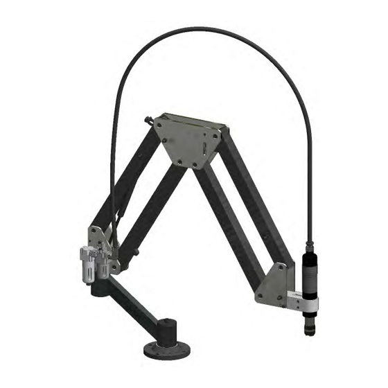
INSTALLATION & OPERATIONS MANUAL
FLEXARM S-36 & M-60
FlexArm Inc.
Division of Midwest Specialties, Inc.
705 Commerce Drive
Wapakoneta, Ohio 45895
419-738-8147
800-837-2503 (toll free)
www.flexmachinetools.com
Table of
Contents
Previous
Page
Next
Page
1
2
3
4
5
Advertisement
Table of Contents
Need help?
Do you have a question about the S-36 and is the answer not in the manual?
Ask a question
Questions and answers
Related Manuals for FlexArm S-36
Racks & Stands FlexArm A-32 Installation & Operation Manual
(26 pages)
Racks & Stands FlexArm FLEXARM RNR Installation & Operation Manual
(29 pages)
Racks & Stands FlexArm B-19 RG Manual
With rotational gimbal (12 pages)
This manual is also suitable for:
M-60
Table of Contents
Print
Rename the bookmark
Delete bookmark?
Delete from my manuals?
Login
Sign In
OR
Sign in with Facebook
Sign in with Google
Upload manual
Upload from disk
Upload from URL


Need help?
Do you have a question about the S-36 and is the answer not in the manual?
Questions and answers