
Related Manuals for Lauper Instruments AMETEK mocon PERMATRAN-W 3/34

Summary of Contents for Lauper Instruments AMETEK mocon PERMATRAN-W 3/34
- Page 1 PERMATRAN-W ® Model 3/34 Operator’s Manual Revision P Lauper Instruments AG Gas-Detection Irisweg 16B CH-3280 Murten Tel. +41 26 672 30 50 info@lauper-instruments.ch www.lauper-instruments.ch Part Number 143-196...
- Page 2 Trademarks & Patents MOCON and PERMATRAN-W are registered trademarks of Mocon, Inc. For information on applicable patents see: https://www.ametekmocon.com/aboutus/legal/intellectualproperty...
- Page 3 PERMATRAN-W Model 3/34 Operator’s Manual About This Manual About This Manual This manual explains how to set up and use the PERMATRAN-W Model 3/34 Water Vapor Transmission Rate System. This manual is designed for viewing electronically. Most references to other sections or chapters in this document are hyperlinks which can be used to navigate to the referenced section.
-
Page 4: Safety Information
Safety Information PERMATRAN-W Model 3/34 Operator’s Manual Safety Information Be sure to read and understand this section and all other applicable chapters of the Operator's Manual and all on-product safety signs before setting up, operating, and maintaining this analyzer. Safety signs appear in this manual and on the analyzer. All safety signs are identified by the words WARNING and CAUTION. -
Page 5: Table Of Contents
PERMATRAN-W Model 3/34 Operator’s Manual Table of Contents Table of Contents About This Manual ............................iii Safety Information ............................iv Chapter 1: Introduction..........................1-1 Features ............................... 1-2 Permeation Test Overview ........................1-3 Individual Zero Phase ........................1-3 Conditioning the Sample ........................ 1-3 ReZero State .......................... - Page 6 Table of Contents PERMATRAN-W Model 3/34 Operator’s Manual Permeant Sensor Accuracy Check ....................... 5-1 Performing a Permeant Sensor Calibration ..................5-1 Permeant Sensor Calibration Test Setup ..................... 5-2 Chapter 6: Testing Flat Film Samples ....................... 6-1 Testing Suggestions ..........................6-1 Preparing for a Film Test ........................
- Page 7 PERMATRAN-W Model 3/34 Operator’s Manual Table of Contents Environmental Requirements ......................10-1 Electrical Requirements ........................10-1 Gas Supply Requirements ......................... 10-2 Operational Capabilities ........................10-2 Environmental Chamber Specifications ....................10-3 Transmission Rate Range and Repeatability Capabilities ..............10-4 Appendix A: Site Preparation Instructions ....................A-1 Appendix A: Site Preparation Instructions ......................
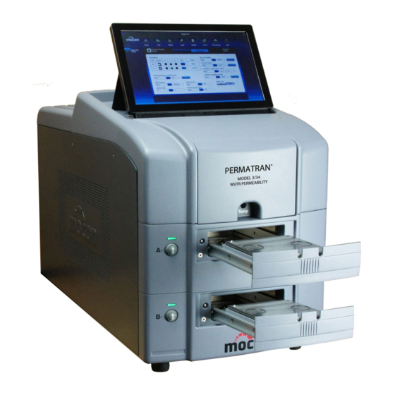
- Page 8 Table of Contents PERMATRAN-W Model 3/34 Operator’s Manual Figures Figure 1-1: PERMATRAN-W Model 3/34 System ..................1-1 Figure 1-2: The PERMATRAN-W Model 3/34 - 100% RH Test Cell ............1-4 Figure 1-3: The PERMATRAN-W Model 3/34 - Generated RH Test Cell ..........1-5 Figure 2-1: Front Panel Parts and Controls ....................
-
Page 9: Chapter 1: Introduction
PERMATRAN-W Model 3/34 Operator’s Manual Introduction Chapter 1: Introduction This chapter provides a brief overview of the PERMATRAN-W Model 3/34 Water Vapor Transmission Rate System. Read this chapter to get an overview of: • The features of the PERMATRAN-W Model 3/34 system •... -
Page 10: Features
Introduction PERMATRAN-W Model 3/34 Operator’s Manual Features The following features of the PERMATRAN-W Model 3/34 Water Vapor Transmission Rate System make it very versatile and easy to use: Fully automatic (Hands Off) testing. • Reduced test times (less total time to achieve a Test Result).* •... -
Page 11: Permeation Test Overview
PERMATRAN-W Model 3/34 Operator’s Manual Introduction Permeation Test Overview A “Permeation Test” consists of up to two phases that are performed using a Test Cell. The “Cell” may contain a flat film sample or be connected to a package fixture. The Test Phase (always present) is used to measure the transmission rate of the test sample. -
Page 12: Report Generation
Introduction PERMATRAN-W Model 3/34 Operator’s Manual Report Generation You can request a report for one or both cells at any time until a new permeation test is started. See the instrument Help System for information on printing reports. Measuring Water Vapor Transmission Rate To make an accurate transmission rate measurement a known concentration Test Gas (usually 100% Water vapor) is applied to one side of the barrier material to be tested and the other side is swept with an water vapor free Carrier Gas (nitrogen). -
Page 13: Figure 1-3: The Permatran-W Model 3/34 - Generated Rh Test Cell
PERMATRAN-W Model 3/34 Operator’s Manual Introduction Flush Gas In Carrier In Carrier Out Flush Gas Out Test Gas Out Test Gas In Figure 1-3: The PERMATRAN-W Model 3/34 - Generated RH Test Cell MOCON, Inc. Revision P... -
Page 14: Testing Films And Packages
Introduction PERMATRAN-W Model 3/34 Operator’s Manual Testing Films and Packages The PERMATRAN-W Model 3/34 can measure the Water Vapor Transmission Rate of film samples or entire packages. To test a film sample it is prepared and mounted in a Test Cell. The test cell is used to maintain the film sample at a specified temperature. -
Page 15: Chapter 2: Setting Up
PERMATRAN-W Model 3/34 Operator’s Manual Setting Up Chapter 2: Setting Up This chapter provides information on how to set up a PERMATRAN-W Model 3/34 and prepare it for use. Read this chapter to learn about: Unpacking the System • • Preparing for System Installation •... -
Page 16: Front Panel Parts And Controls
Setting Up PERMATRAN-W Model 3/34 Operator’s Manual Front Panel Parts and Controls The names and locations of the parts and controls located on the front of the instrument are shown in Figure 2-1, Figure 2-2 and Table 2.1. Figure 2-1: Front Panel Parts and Controls Revision P MOCON, Inc. -
Page 17: Figure 2-2: Front Panel Parts And Controls
PERMATRAN-W Model 3/34 Operator’s Manual Setting Up Figure 2-2: Front Panel Parts and Controls Item Name Description Cell B Load/Unload button This button is used to Load and Unload the Test Cell Cell B Status Indicator This indicator is used to show the Status of Cell B Cell A Load/Unload button This button is used to Load and Unload the Test Cell Cell A Status Indicator... -
Page 18: Back Panel Parts And Controls
Setting Up PERMATRAN-W Model 3/34 Operator’s Manual Back Panel Parts and Controls The names and locations of the parts and controls located on the back of the instrument are shown in Figure 2-3 and Table 2.2. Figure 2-3: Back Panel Parts and Controls Item Name Description... -
Page 19: Carrier Gas (Nitrogen)
PERMATRAN-W Model 3/34 Operator’s Manual Setting Up Carrier Gas (Nitrogen) The PERMATRAN-W Model 3/34 requires a Carrier Gas that is 99.7% nitrogen. A standard T size cylinder will typically provide sufficient gas to operate a single instrument for several weeks. Gas Distribution System Each instrument ships with a local regulator/isolation device (called a Regulator Tee) that can be used to connect the instrument to a common Carrier Gas distribution system. -
Page 20: Connecting The Gas Lines
Setting Up PERMATRAN-W Model 3/34 Operator’s Manual Connecting the Gas Lines The PERMATRAN-W Model 3/34 has a gas inlet for connection of the Carrier Gas (nitrogen) supply. This compression fitting is intended for use with 1/8” copper tubing. Refer to Figure 2-3 and Figure 2-4 for the location of the fitting and an example of plumbing system diagram. - Page 21 PERMATRAN-W Model 3/34 Operator’s Manual Setting Up Connect the inlet fitting on the regulator tee to the output fitting on the Desiccant Tower using the tubing a nuts and a ferrule. Make sure the tube is inserted all the way into the fitting on the Desiccant Tower before tightening the knurled nut.
-
Page 22: Setting The Gas Supply Pressure
Setting Up PERMATRAN-W Model 3/34 Operator’s Manual Setting the Gas Supply Pressure Set the Gas Supply Pressure as follows: Set the Carrier Gas cylinder or main line supply regulator pressure to 35 psi. Set the pressure on the Carrier Gas regulator-tee so that the gauge reads29 psi. Caution: The maximum Carrier Gas pressure to the instrument must not exceed 32 psi. -
Page 23: Chapter 3: Preparing For A Test
PERMATRAN-W Model 3/34 Operator’s Manual Preparing for a Test Chapter 3: Preparing for a Test This chapter provides information on how to prepare for a permeation test. Read this chapter to learn about: Testing Basics • • How Barrier Properties Affect Testing •... -
Page 24: Testing Mixed Barriers
Preparing for a Test PERMATRAN-W Model 3/34 Operator’s Manual Testing Mixed Barriers Simultaneously testing barriers with widely divergent transmission rates is not recommended. The data for both samples may not be accurate when there is a large difference in the two transmission rates. If during a test there is a large difference in the transmission rates, set one cell to Idle and continue testing the other one. -
Page 25: The Sample Conditioning Time
PERMATRAN-W Model 3/34 Operator’s Manual Preparing for a Test The Sample Conditioning Time When you condition a sample in the test cell, carrier gas and test gases are routed to the test cell as they are during testing. However, the carrier gas is not routed to the water vapor sensor. This conditioning period allows a sample barrier to acclimate to the conditions within the test cell. -
Page 26: Determining When To Stop A Test
Preparing for a Test PERMATRAN-W Model 3/34 Operator’s Manual Determining When to Stop a Test The setting used for the “Test Mode” parameter determines how and when a transmission rate test is stopped (Test Completion). Four different methods of stopping a transmission rate test are provided. The four methods are: “Continuous”, “Standard”, “Convergence By Cycles”... -
Page 27: Chapter 4: Using The Instrument Software
PERMATRAN-W Model 3/34 Operator’s Manual Using the Instrument Software Chapter 4: Using the Instrument Software This chapter provides an overview of the software system used to operate the PERMATRAN-W Model 3/34. Detailed information on how to use the instrument software can be found in the Instrument Help System. Read this chapter to learn about: •... -
Page 28: Instrument Software Structure And Organization
Using the Instrument Software PERMATRAN-W Model 3/34 Operator’s Manual Instrument Software Structure and Organization All of the User Interface and Instrument Control functions of your permeation system are accessed through the Instrument Software. The User Interface consists of a Title bar, an Icon bar, and the Workspace The “Title”... -
Page 29: Chapter 5: Permeant Sensor Calibration
PERMATRAN-W Model 3/34 Operator’s Manual Calibrating the Permeant Sensor Chapter 5: Permeant Sensor Calibration You will need to calibrate the system to ensure accuracy in determining water vapor transmission rates. Calibration also ensures proper automatic compensation in the transmission rates when environmental and other factors cause the system to drift. -
Page 30: Permeant Sensor Calibration Test Setup
Calibrating the Permeant Sensor PERMATRAN-W Model 3/34 Operator’s Manual Calibration of the permeant (water vapor) sensor is a two-step process. First, a film sample with a known transmission rate must be tested. Refer to the “Permeant Sensor Calibration Test Setup” in this chapter for information on setting up a film test. - Page 31 PERMATRAN-W Model 3/34 Operator’s Manual Calibrating the Permeant Sensor Cell Temperature: If using certified films, the test temperature must be 37.8 °C. If calibrating with another known film, use the temperature at which the transmission rate for the film was measured. Instrument ReZero: Enabled ReZero Frequency:...
- Page 32 Calibrating the Permeant Sensor PERMATRAN-W Model 3/34 Operator’s Manual Monitor the progress of the test using the “Cell Status” and “Instrument Status” screens. When the reference sample has reached equilibrium, advance the cell to the “Test Complete” state. The sample is usually considered to be at equilibrium when there is no discernable trend in the data.
-
Page 33: Chapter 6: Testing Flat Film Samples
PERMATRAN-W Model 3/34 Operator’s Manual Testing Flat Films Chapter 6: Testing Flat Film Samples This chapter contains information on how to test flat film samples. Suggestions on how to maximize the accuracy of your results and procedures describing how to perform the test are discussed. Read this chapter to learn about: •... -
Page 34: Preparing For A Film Test
Testing Flat Films PERMATRAN-W Model 3/34 Operator’s Manual Preparing for a Film Test Before a test can be conducted there are a number of tasks that must be performed: The samples to be tested must be prepared. The samples must be mounted in a Test Cell and Loaded into the instrument. Finally, if the test requires a Generated RH the Humidifier must be checked and filled if necessary. -
Page 35: Orienting The Sample
PERMATRAN-W Model 3/34 Operator’s Manual Testing Flat Films Orienting the Sample When mounting test samples, orientation can be important. Edge leakage or oxidation on some materials can affect the test result. It is important to place the “barrier side towards the carrier”. Follow the guidelines below to minimize edge leakage and oxidation effects. -
Page 36: Using A Generated Rh Test Gas
Testing Flat Films PERMATRAN-W Model 3/34 Operator’s Manual Using a Generated RH Test Gas The PERMATRAN-W Model 3/34 has the capability of generating a controlled RH from 5 to 90% for the Model H and 50 to 90% for the Model G for the Test Gas. A Generated RH Test Gas is created by moving pressurized gas through a humidifier filled with HPLC-grade water and mixing the wet gas with a dry gas in the appropriate ratios. -
Page 37: Humidifier Ports And Controls
PERMATRAN-W Model 3/34 Operator’s Manual Testing Flat Films Close the Fill Valve and remove the syringe. Start a ReZero examination using the GoTo control. Humidifier Ports and Controls The ports and controls used to fill the Water Reservoir used for Generated RH testing are illustrated in the figure and table below. -
Page 38: Mounting A Sample In The Test Cell
Testing Flat Films PERMATRAN-W Model 3/34 Operator’s Manual Mounting a Sample in the Test Cell Follow the instructions below to mount a film sample in the Test Cell: Note: For information on cutting and preparing the film samples refer to the sections on “Sample Size”, “Using Masks”... -
Page 39: Loading And Unloading The Test Cell
PERMATRAN-W Model 3/34 Operator’s Manual Testing Flat Films Loading and Unloading the Test Cell The PERMATRAN-W Model 3/34 uses a pneumatic system to clamp, unclamp and eject the Test Cell. The Test cell must be manually loaded and unloaded from the instrument. To Unload the Test Cell from the Cell Tray follow the instructions below (refer to Figure 6-3): Press the Cell Load/Unload button on the front of the instrument (see Figure 2-1). -
Page 40: Setting Up And Starting A Film Test
Testing Flat Films PERMATRAN-W Model 3/34 Operator’s Manual Setting Up and Starting a Film Test After the samples are loaded and the instrument is ready there are a number of test parameters that must be set. There are two types of test parameters, cell parameters and instrument parameters. Cell Parameters are specific to each cell (Sample ID, Sample Thickness). -
Page 41: Chapter 7: Testing Packages
PERMATRAN-W Model 3/34 Operator’s Manual Testing Packages Chapter 7: Testing Packages This chapter contains information on how to test packages. Suggestions on how to maximize the accuracy of your results and procedures describing how prepare for and perform a package test are discussed. Read this chapter to learn about: •... -
Page 42: Preparing The Instrument For A Package Test
Testing Packages PERMATRAN-W Model 3/34 Operator’s Manual Preparing the Instrument for a Package Test To accommodate package testing the film Test Cell must be replaced with the optional Package Adapter. The tubing to the package fixture should be connected to the Package adapter before placing it into the Test Cell tray. -
Page 43: Package Testing Methods
PERMATRAN-W Model 3/34 Operator’s Manual Testing Packages Package Testing Methods There are many different types of packages and most of them can be tested on the PERMATRAN-W Model 3/34. Most packages can be classified as belonging to one of two categories, rigid packages or flexible packages. -
Page 44: Package Mounting Methods
Testing Packages PERMATRAN-W Model 3/34 Operator’s Manual Package Mounting Methods The type of fixture required is usually dependent on the type of package, rigid or flexible. Rigid packages and semi-rigid packages (bottles, trays or cups) can often be mounted on a Package Plate. A “fixture” for Flexible packages is created by sealing all unnecessary openings and then sealing (usually with epoxy) two tubes into the package envelope to allow the Carrier Gas to “sweep”... -
Page 45: Mounting Pouches And Bags
PERMATRAN-W Model 3/34 Operator’s Manual Testing Packages Mounting Pouches and Bags Flexible packages require a different mounting method than rigid packages. Flexible packages can be mounted with the carrier gas tubes entering the top or bottom of the package. The following instructions, along with Figure 7-3 and Figure 7-4 will assist you in mounting the package. Make two cuts in the package just large enough for the ends of the tubing to slip through. -
Page 46: Setting Up And Starting A Package Test
Testing Packages PERMATRAN-W Model 3/34 Operator’s Manual Setting Up and Starting a Package Test After the samples are loaded and the instrument is ready there are a number of test parameters that must be set. There are two types of test parameters, cell parameters and instrument parameters. Cell Parameters are specific to each cell (Sample ID, Sample Thickness). -
Page 47: Chapter 8: Maintenance
PERMATRAN-W Model 3/34 Operator’s Manual Maintenance Chapter 8: Maintenance This contains information on how to clean and maintain the PERMATRAN-W Model 3/34. Read this chapter to learn about: Cleaning the Instrument • • Cleaning the Test Cell • Cleaning the Air Filters •... -
Page 48: Cleaning The Air Filters
Maintenance PERMATRAN-W Model 3/34 Operator’s Manual Cleaning the Air Filters Periodically the air filter on the back of the instrument should be removed and cleaned. The recommended interval is twice a year (or whenever there is a significant buildup of dust). If the filter is not cleaned on a regular basis air will not circulate properly through the cooling system. -
Page 49: Cleaning The Test Cells
PERMATRAN-W Model 3/34 Operator’s Manual Maintenance Cleaning the Test Cells Periodically the test cells should be cleaned to remove any excess buildup of grease. Alcohol can be used to remove any residue from the High Vacuum grease. Inspect the gas ports and TrueSeal flush ring and remove any grease that could obstruct the flow of gas. Maintaining the Test Cells Periodically the test cells should be examined and any damaged, deformed, cracked or brittle o-rings replaced. -
Page 50: 100% Rh Test Cell Components And Part Numbers
Maintenance PERMATRAN-W Model 3/34 Operator’s Manual 100% RH Test Cell Components and Part Numbers The parts of the test cell used for 100% RH testing are shown in Figure 8-2 below. Refer to Table 8.1 for the associated part numbers and the quantity used. To order replacement parts contact MOCON in the USA at (763) 493-6370. -
Page 51: Generated Rh Test Cell Components And Part Numbers
PERMATRAN-W Model 3/34 Operator’s Manual Maintenance Generated RH Test Cell Components and Part Numbers The parts of the test cell used for Generated RH testing are shown in Figure 8-3 below. Refer to Table 8.2 for the associated part numbers and the quantity used. To order replacement parts contact MOCON in the USA at (763) 493-6370. -
Page 52: Changing The Desiccant
Maintenance PERMATRAN-W Model 3/34 Operator’s Manual Changing the Desiccant The desiccant chamber is located in-line between the regulator tee assembly and the nitrogen tank. Change the desiccant whenever the blue indicator starts to turn pink. Refer to Figure 8-4 and follow the directions below to change the desiccant: Warning! The desiccant chamber contains high pressure, and will cause personal injury... -
Page 53: Figure 8-4: The Desiccant Chamber
PERMATRAN-W Model 3/34 Operator’s Manual Maintenance Caution: To eliminate the possibility of gross leaks, you should make sure the copper tubing is fully inserted into the desiccant chamber fittings and that the o-ring and ferrule are installed and positioned correctly (see Figure 8-4). Figure 8-4: The Desiccant Chamber MOCON, Inc. -
Page 54: System Standby
Maintenance PERMATRAN-W Model 3/34 Operator’s Manual System Standby When a test series is complete, the instrument sets the sensor to the Bypass state. In this position the sensor is isolated and protected from inadvertent exposure to large amounts of water vapor. If no testing will be performed for an extended period of time (overnight or weekend) leave a film mounted and clamped in the test cells. -
Page 55: Chapter 9: Troubleshooting
PERMATRAN-W Model 3/34 Operator’s Manual Trouble Shooting Chapter 9: Troubleshooting This chapter contains information to assist you in solving problems that may occur during the operation of the instrument. Read this chapter to learn about: • Error Messages and Warnings •... -
Page 56: Recovering From A Sensor Over-Range Condition
Troubleshooting PERMATRAN-W Model 3/34 Operator’s Manual Recovering from a Sensor Over-Range Condition A severe over range condition will terminate the test sequence on both cells. If you see a red Cell Status indicator (on the front of the instrument), the test has failed due to a permeant sensor over-range condition. -
Page 57: Chapter 10 Specifications
PERMATRAN-W Model 3/34 Operator’s Manual Specifications Chapter 10 Specifications This chapter contains the specifications of the PERMATRAN-W Model 3/34. Read this chapter for details about: Physical specifications • Environmental requirements • • Electrical requirements • Gas Supply requirements • Operational capabilities Physical Specifications Height Width... -
Page 58: Gas Supply Requirements
Specifications PERMATRAN-W Model 3/34 Operator’s Manual Gas Supply Requirements Gas Composition Nitrogen (99.7% N or better) Supply Pressure, Nominal 29 PSI, (2.0 Bar), (200 kPa) Supply Pressure, Maximum 32 PSI, (2.2 Bar), (220 kPa) Carrier Gas Supply Pressure, Minimum 26 PSI, (1.8 Bar), (179 kPa) Flow Rate, Maximum 555 cc/minute (Test Active 100cc/min) Flow Rate, Minimum... -
Page 59: Environmental Chamber Specifications
PERMATRAN-W Model 3/34 Operator’s Manual Specifications Environmental Chamber Specifications Temperature Range 5 °C to 50 °C ± 0.5 °C Humidity Control None Table 10-6: Environmental Chamber Specifications MOCON, Inc. Revision P 10-3... -
Page 60: Transmission Rate Range And Repeatability Capabilities
Specifications PERMATRAN-W Model 3/34 Operator’s Manual Transmission Rate Range and Repeatability Capabilities Minimum Carrier Exam Calibration Testing Range Repeatability Flow Time Standard Required Model G 2.5 to 100 gm/(m -day) Certified Film 0.161 to 6.45 gm/(100 -day) 25 minutes P/N 052-052 +/- 2.0% of Reading sccm 0.0125 to 0.50 gm/(pkg-day) -
Page 61: Appendix A: Site Preparation Instructions
PERMATRAN-W Model 3/34 Operator’s Manual Site Preparation Instructions Appendix A: Site Preparation Instructions Part Number 140-217 (See next page) MOCON, Inc. Revision P... - Page 62 Site Preparation Instructions PERMATRAN-W Model 3/34 Operator’s Manual P/N 140-217 Revision B 7500 Mendelssohn Avenue North Minneapolis, MN 55428 U.S.A. Telephone 763-493-6370 Web Site: www.ametekmocon.com SITE PREPARATION INSTRUCTIONS IMPORTANT! REQUIREMENTS FOR THE START-UP OF THE PERMATRAN-W Model 3/34 SYSTEM ® The following must be furnished by the customer before a new PERMATRAN-W Model 3/34 can be set up.
- Page 63 PERMATRAN-W Model 3/34 Operator’s Manual Site Preparation Instructions REGULATOR ASSEMBLY - If the customer chooses to purchase the optional regulator, then the gas cylinder is the only item that must be supplied by the customer. The regulator assembly contains everything else that is needed. COPPER TUBING - Metallic tubing is required for connecting the nitrogen supply to the rear panel of the instrument.
- Page 64 Site Preparation Instructions PERMATRAN-W Model 3/34 Operator’s Manual Machinery and air conditioners can generate a large amount of electrical interference on the AC power lines. These disturbances can interfere with the operation of the system unless steps are taken to isolate the power disturbances from the power lines serving the instrument.
-
Page 65: Appendix B: Spare Parts
PERMATRAN-W Model 3/34 Operator’s Manual Spare Parts Appendix B: Spare Parts The following is a list of the spare parts that are available for the PERMATRAN-W Model 3/34. To order, contact MOCON in the USA at (763) 493-6370. Part Unit Of Description Quantity Number... - Page 66 Spare Parts PERMATRAN-W Model 3/34 Operator’s Manual Part Unit Of Description Quantity Number Measure 052-054 Certified Film, #4 Green, 5 mil Poly, 0.3 sq cm, 052-055 Certified Film, #3 Blue, 1 mil Aclar, 30 sq cm, 110-559 Assy, Package Mounting Fixture, 4 X 4 105-259 Mask, Aluminum Foil, 4X4, Blank 130-015...
-
Page 67: Appendix C: Warranty And Service Policies
PERMATRAN-W Model 3/34 Operator’s Manual Warranty and Service Policies Appendix C: Warranty and Service Policies Part Number: 032-846, Warranty Policy Part Number: 032-847, International Service Policy Part Number: 032-848, Domestic Service Policy (See next pages) MOCON, Inc. Revision P... - Page 68 Warranty and Service Policies PERMATRAN-W Model 3/34 Operator’s Manual Part Number 032-846 Revision G 7500 Mendelssohn Avenue North Minneapolis, MN 55428 USA Telephone 763-493-6370 Web Site: www.ametekmocon.com WARRANTY POLICY STATEMENT OF LIMITED WARRANTY MOCON, Inc. warrants that any part of any MOCON instrument or accessory ( “ I n s t r u m e n t ” ) which proves to be defective in material or workmanship during the warranty period will be repaired by MOCON "certified"...
- Page 69 PERMATRAN-W Model 3/34 Operator’s Manual Warranty and Service Policies • If field training is not purchased, the warranty period is Ninety days from date of shipment from MOCON’s factory. Units or systems without MOCON offered field training. • One year from date of shipment from MOCON’s factory. Spare parts, repairs and accessories when purchased separately and not a part of a new instrument order.
- Page 70 Warranty and Service Policies PERMATRAN-W Model 3/34 Operator’s Manual Part Number 032-847 Revision D 7500 Mendelssohn Avenue North Minneapolis, MN 55428 USA Telephone 763-493-6370 Web Site: www.ametekmocon.com INTERNATIONAL SERVICE POLICY MOCON offers a complete range of service options to purchasers of MOCON instrumentation and systems. ♦♦♦SERVICE PERFORMED WITHIN THE WARRANTY PERIOD♦♦♦...
- Page 71 PERMATRAN-W Model 3/34 Operator’s Manual Warranty and Service Policies Part Number 032-848 Revision E 7500 Mendelssohn Avenue North Minneapolis, MN 55428 USA Telephone 763-493-6370 Web Site: www.ametekmocon.com DOMESTIC SERVICE POLICY MOCON offers a complete range of service options to purchasers of MOCON instrumentation and systems. ♦♦♦SERVICE PERFORMED WITHIN THE WARRANTY PERIOD♦♦♦...
- Page 72 Warranty and Service Policies PERMATRAN-W Model 3/34 Operator’s Manual Please refer to the latest version of MOCON’s Warranty Policy sheet for warranty information. MOCON IS A REGISTERED TRADEMARK OF MOCON, INC. Copyright© 2021 MOCON, INC. All rights reserved. Revision P MOCON, Inc.
-
Page 73: Appendix D: Theory Of Operation
PERMATRAN-W Model 3/34 Operator’s Manual Theory of Operation Appendix D: Theory of Operation How the Water Vapor Transmission Rate is measured When a film is installed in a Test Cell, it is exposed to a continuous flow of dry nitrogen gas across the one side (the Carrier Gas side) and an RH on the other (the Test Gas side). -
Page 74: Barrier Temperature
Theory of Operation PERMATRAN-W Model 3/34 Operator’s Manual Factors that Affect the Transmission Rate of a Barrier Material The water vapor transmission rate of barrier materials is affected by several factors: Barrier test temperature • Test Gas (water vapor) concentration effect on driving force •... -
Page 75: How A Humidified Test Gas Is Generated
PERMATRAN-W Model 3/34 Operator’s Manual Theory of Operation How a Humidified Test Gas is Generated A Humidified Test Gas is created by moving pressurized gas through a humidifier filled with HPLC-grade water and mixing the wet gas with a dry gas in the appropriate ratios. A mixing valve is used to “mix”... -
Page 76: How The Auto-Test Method Works
Theory of Operation PERMATRAN-W Model 3/34 Operator’s Manual How the Auto-Test Method Works The Auto-Test Method utilizes an internal rule-set to dynamically optimize how a permeation test is performed. The Auto-Test Method also utilizes an advanced dynamic convergence algorithm to determine when the sample has reached equilibrium. -
Page 77: Appendix E: Electrical And Plumbing Diagrams
PERMATRAN-W Model 3/34 Operator’s Manual Electrical and Plumbing Diagrams Appendix E: Electrical and Plumbing Diagrams Title Part Number Plumbing Diagram, PERMATRAN-W Model 3/34 051-953 Electrical Diagram, PERMATRAN-W Model 3/34 051-954 MOCON, Inc. Revision P... - Page 78 Electrical and Plumbing Diagrams PERMATRAN-W Model 3/34 Operator’s Manual Figure E-1: Plumbing Diagram Page 1 Revision P MOCON, Inc.
- Page 79 PERMATRAN-W Model 3/34 Operator’s Manual Electrical and Plumbing Diagrams Figure E-2: Plumbing Diagram Page 2 MOCON, Inc. Revision P...
- Page 80 Electrical and Plumbing Diagrams PERMATRAN-W Model 3/34 Operator’s Manual Figure E-3: Electrical Diagram Page 1 Revision P MOCON, Inc.
- Page 81 PERMATRAN-W Model 3/34 Operator’s Manual Electrical and Plumbing Diagrams Figure E-4: Electrical Diagram Page 2 MOCON, Inc. Revision P...
- Page 82 Electrical and Plumbing Diagrams PERMATRAN-W Model 3/34 Operator’s Manual Figure E-5: Electrical Diagram Page 3 Revision P MOCON, Inc.
-
Page 83: Appendix F: Preparing Rh Calibration Standards
PERMATRAN-W Model 3/34 Operator’s Manual Preparing RH Calibration Standards Appendix F: Preparing RH Calibration Standards To calibrate or check the RH probes used in the PERMATRAN-W Model 3/34, requires RH reference values (or standards). A RH Calibration Standard consists of a saturated salt solution or molecular sieve in a “Calibration Flask”. -
Page 84: Preparing A High Level Calibration Standard
Preparing RH Calibration Standards PERMATRAN-W Model 3/34 Operator’s Manual Preparing a High Level Calibration Standard A High Level RH Calibration standard can be prepared using a salt solution as follows: Chose the appropriate salt for the calibration standard. See “Choosing a Salt for a Calibration Standard”... -
Page 85: Appendix G: Compliance
PERMATRAN-W Model 3/34 Operator’s Manual Compliance Appendix G: Compliance MOCON, Inc. Revision P...
Need help?
Do you have a question about the AMETEK mocon PERMATRAN-W 3/34 and is the answer not in the manual?
Questions and answers