Table of Contents

Related Manuals for Albalá Ingenieros TTD2000C01


Summary of Contents for Albalá Ingenieros TTD2000C01
- Page 1 TTD2000C01 DISTRIBUTOR WITH 1 INPUT TO 4 OUTPUTS FOR TTL OR 10 MHz (50 OR 75 OHMS IMPEDANCE) REFERENCE SIGNAL Version 1.0 Albalá Ingenieros, S.A. 07 June 2017 - © Albalá Ingenieros S.A. - All rights reserved Medea, 4 - 28037 Madrid - Spain...
- Page 2 TTD2000C01...
-
Page 3: Table Of Contents
4. OPERATION ........................15 4.1. Front panel description ......................15 4.2. Functional description ....................... 16 4.3. Module remote control and supervision ................18 4.3.1. Details of the TTD2000C01 registers ................19 5. GLOSSARY ........................21 6. REGULATIONS ........................23 7. VERSIONS ......................... 25... - Page 4 TTD2000C01...
-
Page 5: Description
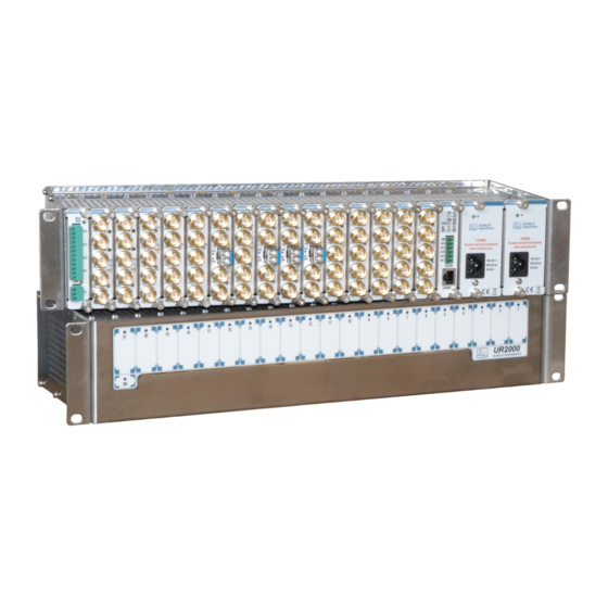
SNMP management and the ability to record events in a file including date and time information for further analysis. The TTD2000C01 is a TL2000 terminal line module and can be housed in a two rack unit (2 RU) UR2000 mounting frame. -
Page 6: Features
GPS2000C01 delivers to the bus of the mounting frame. In such cases, each TTD2000C01 installed in the frame provides five outputs that can be: all 1 PPS, all 10 MHz or two of one type and three of the other as desired. -
Page 7: Block Diagram
Albalá Ingenieros | Manual TTD2000C01 1.3. Block diagram... - Page 8 Albalá Ingenieros | Manual TTD2000C01 TTD2000C01...
-
Page 9: Specifications
Albalá Ingenieros | Manual TTD2000C01 2. SPECIFICATIONS Signal amplifier Gain 0 dB ± 0.5 dB Dynamic range -1.5 .. +3.5 V Dynamic range + 13 dBm 3 dB cuttoff frequency: Lower DC referece level 0 dB at 70 MHz Upper >50 MHz referece level 0 dB... - Page 10 Albalá Ingenieros | Manual TTD2000C01 TTD2000C01...
-
Page 11: Installation
• The TTD2000C01 module and the mounting frame should always be installed, maintained, operated and removed by personnel with sufficient technical qualifications. The equipment should never be placed in damp areas, near splashing liquid, or in explosive or corrosive atmospheres. -
Page 12: Environmental Considerations
1 - Remove the blank panel covering the front of the empty slot chosen for installing the TTD2000C01 in the mounting frame. 2 - Insert the TTD2000C01 module into the front of the mounting frame. The edges of the card slide into two plastic guides inside the mounting frame. -
Page 13: Interconnection
Albalá Ingenieros | Manual TTD2000C01 3.5. Interconnection The arrangement of the front panel connectors of the TTD2000C01 module is shown in the following figure. Front panel of the TTD2000C01 The TTD2000C01 provides five BNC connectors. Four of these (OUT1, OUT2, OUT3 and OUT4) are always used as outputs. - Page 14 Albalá Ingenieros | Manual TTD2000C01 TTD2000C01...
-
Page 15: Operation
Albalá Ingenieros | Manual TTD2000C01 4. OPERATION This section describes the significance of the front panel indicators of the TTD2000C01 module and their remote control and monitoring ability. 4.1. Front panel description The appearance of the front panel and the elements it contains are shown in the following illustration. -
Page 16: Functional Description
TTD2000C01 OUT 1.2, OUT 3.4.5: This LED lights up only when the TTD2000C01 acts as an auxiliary module for distribution of the reference signals in the bus of a mounting frame. 1PPS. Blue, blinking. Indicates that a one pulse-per-second signal has been detected on the TTL line of the bus and that this signal is being delivered to that output. - Page 17 Albalá Ingenieros | Manual TTD2000C01 The impedance of the input and the outputs of the module can be set to 50 or 75 Ω in order to adapt to the type of signal being distributed.
-
Page 18: Module Remote Control And Supervision
Albalá Ingenieros | Manual TTD2000C01 4.3. Module remote control and supervision The TTD2000C01 can optionally be remotely controlled/supervised. In order to perform remote configuration and supervision of the module an optional TL2000 family remote communications controller must be installed in the mounting frame. -
Page 19: Details Of The Ttd2000C01 Registers
TTD2000C01 The following functions of the TTD2000C01 can be performed remotely: - Supervision of the presence and type of signals being distributed by the TTD2000C01. - Configuration of the operating mode and impedance of both the input and the outputs. - Page 20 Albalá Ingenieros | Manual TTD2000C01 FR_OTHER_DET 0x02 0x08 Indicates other frequency TTL signal has been detedted in the front 0=Inactive,1=Active RE_1PPS_DET 0x02 0x10 Indicates 1 PPS signal has been detedted in the rear bus 0=Inactive,1=Active RE_48KHZ_DET 0x02 0x20 Indicates 48 kHz signal has been detedted in the bus...
-
Page 21: Glossary
Albalá Ingenieros | Manual TTD2000C01 5. GLOSSARY 1 PPS One Pulse Per Second. Synchronization signal that consists of one short pulse that is repeated every second. Typically uses TTL levels. - Page 22 Albalá Ingenieros | Manual TTD2000C01 TTD2000C01...
-
Page 23: Regulations
Albalá Ingenieros | Manual TTD2000C01 6. REGULATIONS... - Page 24 Albalá Ingenieros | Manual TTD2000C01 TTD2000C01...
-
Page 25: Versions
Albalá Ingenieros | Manual TTD2000C01 7. VERSIONS Ver. Date Description 02-03-2017 Preliminary Version 07-06-2017 First version... - Page 26 Albalá Ingenieros, S.A. Medea, 4 - 28037 Madrid Spain +34 913274453 www.albalaing.com info@albalaing.com...
Need help?
Do you have a question about the TTD2000C01 and is the answer not in the manual?
Questions and answers