
Summary of Contents for I.CH Motion 3P20M
- Page 1 TECHNICAL DOCUMENT OWNER’S GUIDE 3P20M HYBRID STEPPER MOTOR DRIVER ©2020 by I.CH Motion Co.,Ltd.. All Rights Reserved Page 1...
- Page 2 13. Protection Functions ∙∙∙∙∙∙∙∙∙∙∙∙∙∙∙∙∙∙∙∙∙∙∙∙∙∙∙∙∙∙∙∙∙∙∙∙∙∙∙∙∙∙∙∙∙∙∙∙∙∙∙∙∙∙∙∙∙∙∙∙∙∙∙∙∙∙∙∙∙∙∙∙∙∙∙∙∙∙∙∙∙∙∙∙∙∙∙∙∙∙∙∙∙∙∙∙∙∙∙∙∙∙∙∙∙∙∙∙∙∙∙∙∙∙∙∙∙∙∙∙∙∙∙∙∙∙∙∙∙∙∙∙∙∙∙∙∙∙∙∙∙∙∙∙∙∙∙∙∙∙∙∙∙∙∙13 14. Frequently Asked Questions ∙∙∙∙∙∙∙∙∙∙∙∙∙∙∙∙∙∙∙∙∙∙∙∙∙∙∙∙∙∙∙∙∙∙∙∙∙∙∙∙∙∙∙∙∙∙∙∙∙∙∙∙∙∙∙∙∙∙∙∙∙∙∙∙∙∙∙∙∙∙∙∙∙∙∙∙∙∙∙∙∙∙∙∙∙∙∙∙∙∙∙∙∙∙∙∙∙∙∙∙∙∙∙∙∙∙∙∙∙∙∙∙∙∙∙∙∙∙∙∙∙∙∙∙∙∙∙∙∙∙∙∙∙∙∙∙∙∙∙∙∙14 15. Application ∙∙∙∙∙∙∙∙∙∙∙∙∙∙∙∙∙∙∙∙∙∙∙∙∙∙∙∙∙∙∙∙∙∙∙∙∙∙∙∙∙∙∙∙∙∙∙∙∙∙∙∙∙∙∙∙∙∙∙∙∙∙∙∙∙∙∙∙∙∙∙∙∙∙∙∙∙∙∙∙∙∙∙∙∙∙∙∙∙∙∙∙∙∙∙∙∙∙∙∙∙∙∙∙∙∙∙∙∙∙∙∙∙∙∙∙∙∙∙∙∙∙∙∙∙∙∙∙∙∙∙∙∙∙∙∙∙∙∙∙∙∙∙∙∙∙∙∙∙∙∙∙∙∙∙∙∙∙∙∙∙∙∙∙∙∙∙∙∙∙∙14 Note:if you have any problems,please email sales@ichmo.com to to contact us. Page 2 ©I.CH Motion® 2020 ichmo .com Specifications subject to change without notice. Owner's Guide: 3P20M Hybrid Stepper Motor Driver...
- Page 3 1. Introduction These two 3 phase motor(3P20M) drivers can be used to drive 3 and 6 wire stepper motor, whose effect is like servo motor. These drivers have multiple subdivisions, range of current. If you have any interest, please contact us.
-
Page 4: Specification
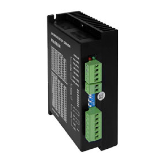
-20℃-+125℃ Weight Approx. 280 gram (9.88 oz) 4-Ф Figure 1: Mechanical Specifications Recommend use side mounting for better heat dissipation. Page 4 ©I.CH Motion® 2020 ichmo .com Specifications subject to change without notice. Owner's Guide: 3P20M Hybrid Stepper Motor Driver... - Page 5 5. Definition of Pin Signal The 3P20M has two connectors, connector P1 for control signals connections, and connector P2 for power and motor connections. The following tables are brief descriptions of the two connectors. More detailed descriptions of the pins and related issues are presented in section 4, 5, 9.
- Page 6 Selecting CW/CCW or PUL/DIR Mode There is a jumper J1 (including pin 1 to pin 9) inside the 3P20M specifically for selecting pulse signal mode. Settings for the one-pulse mode (PUL/DIR) and for the double-pulse mode (CW/CCW) are shown in the following figure. Default mode out of factory is PUL/DIR mode and effective at rising edge.
- Page 7 The 3P20M can accept differential and single-ended control signals (including open-collector, namely common-anode and PNP output, namely common-cathode). The 3P20M has 3 optically isolated logic inputs which are located on connector P1 to accept line driver control signals. These inputs are isolated to minimize or eliminate electrical noises coupled onto the control signals. It’s recommended to use line driver control signals to increase noise immunity of the driver under an interference environment.
-
Page 8: Connecting The Motor
8. Power Supply Selection The 3P20M can match medium and small size stepping motors (from NEMA size 17 to 34) made by I.CH Motion or other motor manufactures around the world. To achieve good driving performances, it is important to select supply voltage and output current properly. Generally speaking, supply voltage determines the high speed performance of the motor, while output current determines the output torque of the driven motor (particularly at lower speed). - Page 9 DIP Setting for Dynamic Current The 3P20M uses an 8-bit DIP switch to set motor dynamic current, standstill current and microstep resolution, as shown below: The first four bits (SW1, 2, 3, 4) of the DIP switch are used to set the dynamic current. Select a setting closest to your motor’s required current.
- Page 10 0.5 second after the last pulse when use automatic idle-current reduction mode. Theoretically, this will reduce motor heating to 36% (due to P=I2*R) of the original value. Page 10 ©I.CH Motion® 2020 ichmo .com Specifications subject to change without notice. Owner's Guide: 3P20M Hybrid Stepper Motor Driver...
-
Page 11: Wiring Notes
A complete stepping system should include stepping motor, stepping driver, power supply and controller (pulse generator). A typical connection is shown in the Figure 6. Page 11 ©I.CH Motion® 2020 ichmo .com Specifications subject to change without notice. Owner's Guide: 3P20M Hybrid Stepper Motor Driver... -
Page 12: Sequence Chart Of Control Signals
In order to avoid some fault operations and deviations, PUL, DIR and ENA signals should abide by some rules, as shown in the figure 7: Figure 7: Sequence chart of control signals Page 12 ©I.CH Motion® 2020 ichmo .com Specifications subject to change without notice. Owner's Guide: 3P20M Hybrid Stepper Motor Driver... -
Page 13: Protection Functions
Attention: Since there is no protection against power leads (+, -) reversal, it is critical to make sure that power supply leads correctly connected to the driver. Otherwise, the driver will be damaged instantly. Page 13 ©I.CH Motion® 2020 ichmo .com Specifications subject to change without notice. Owner's Guide: 3P20M Hybrid Stepper Motor Driver... -
Page 14: Frequently Asked Questions
14. Frequently Asked Questions In the event that your 3P20M doesn’t operate properly, the first step is to identify whether the problem is electrical or mechanical in nature. The next step is to isolate the system component that is causing the problem. As part of this process you may have to disconnect the individual components that make up your system and verify that they operate independently.
Need help?
Do you have a question about the 3P20M and is the answer not in the manual?
Questions and answers