
Related Manuals for p5 FutureNow FNIP-8x16A

Summary of Contents for p5 FutureNow FNIP-8x16A
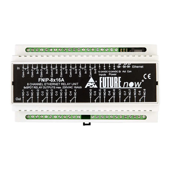
- Page 1 FutureNow FNIP-8x16A Installation and Operations Manual rev 04.12.2019 8 Channel Relay Switch with Local Inputs and IP communication /DIN Rail and Surface Mountable/ Figure 1. The FNIP-8x16A relay module P a g e...
- Page 2 OVERVIEW The FNIP-8x16A is an eight channel relay module used for switching any type of load that doesn’t exceed the specifications. Via its built-in web site and TCP/IP communication, the outputs and inputs can be controlled and monitored from standard network capable devices such as computers, smartphones, web-tablets, etc.
- Page 3 Main features Robust Operation 8 x 230V/16A SPDT general purpose dry contact relay outputs each with both NO and NC contacts 8 x galvanically isolated multi-purpose inputs for manual control or for connecting digital sensors Ultimate Flexibility Monostable switching ...
-
Page 4: Table Of Contents
Table of Content INSTALLATION..............................5 Terminal connections ............................5 Wiring ................................. 7 Outputs ................................8 Local Inputs ................................ 8 Status LED Indicators ............................. 9 CONFIGURATION .............................. 12 Configuration via the web interface ........................12 Network settings ............................... 13 Users and user rights ............................14 Channel settings .............................. -
Page 5: Installation
INSTALLATION WARNING! This equipment shall be installed in a closed cabinet with no access to live parts. Only the top enclosure of the equipment (where the label is affixed) is allowed to be accessed by the operator. Since the module is connected to mains/line voltage, it must be installed by a qualified electrician in accordance with local electrical codes. - Page 6 No. Description Description Output 1 N.O. Inputs Common Output 1 C. Input 1 Output 1 N.C. Inputs Common Output 2 N.O. Input 2 Output 2 C. Inputs Common Output 2 N.C. Input 3 Output 3 N.O. Inputs Common Output 3 C. Input 4 Output 3 N.C.
-
Page 7: Wiring
Wiring A typical wiring diagram is shown in figure 3. Figure 3. Wiring diagram. All outputs in this example are used to switch line voltage on the same phase. Since the outputs provide dry contacts, any voltage that doesn’t exceed the specifications can be switched. After installation, check if the outputs can be toggled via the inputs (only applicable if input power is connected across terminals 43-44.) The status LEDs will assist you in tracking the status of the outputs and see if the inputs are... -
Page 8: Outputs
All wires used and the way they are run must be in accordance with the local electrical codes. Keep mains/line voltage wiring physically separated from Ethernet and signal wiring. Power requirements The module must be powered through terminals 45 and 46 by 10.8V - 36V DC. Please pay attention to the correct polarity. -
Page 9: Status Led Indicators
Connect dry contacts (pushbuttons, standard or momentary switches, relay contacts, etc.) or open collector transistor outputs across the appropriate input terminals and the input common terminal. WARNING! Avoid supplying external voltage to these terminals! All input ports are optically isolated to protect the module against unwanted effects of ground loops, overvoltage or misconnections. - Page 10 Figure 4. The board layout of the FNIP-8x16A Output status LEDs Each output has a dedicated status LED that illuminates solid red when the corresponding output is on. Input status LEDs Each input has a dedicated status LED that illuminates solid green when the corresponding input is activated.
- Page 11 St LED - red The status LED indicates that the boot loader of the module is active. This should only happen during firmware update. Please never disconnect power from the module while this LED is on! If this LED stays on after the firmware update, please contact your dealer! 11 | P a g e...
-
Page 12: Configuration
CONFIGURATION Configuration can be done either via the built-in website or via TCP/IP connection. In the latter case the configuration interface the third party controller provides is used. Configuration via the web interface Use the FNIP Network Discovery Utility software to find all FutureNow IP devices on your network. -
Page 13: Network Settings
The default user name:admin The default password:futurenow The default user has administrator rights and offer access to all settings and functions. Once logged in, you will automatically be directed to the control page. you can see the details in the OPERATION section. You can use the tabs on the top of the screen to navigate between the different control and configuration pages. -
Page 14: Users And User Rights
Figure 6. Network Configuration Page Users and user rights Three different users can be defined, each with three different user rights: admin, actor and observer. Admins have access to all functions, including control of the outputs, monitoring the status of the inputs and outputs and changing all the settings. Actors are allowed to control the outputs and monitor the status of the inputs and the outputs, but are not allowed to change any settings. - Page 15 To change user settings, click on the User tab in the top menu. The user configuration page is shown in Figure 7. Figure 7. User Configuration Page 15 | P a g e...
-
Page 16: Channel Settings
Channel settings On the Channel page the outputs and inputs can be renamed. Input modes can also be chosen here. The input mode determines the logical connection between the input and the output of the same channel. For details on possible input modes and how they work, see Operation via the local inputs section of this document. -
Page 17: Scenes
Scenes Scenes are predefined states of the outputs on the module. FNIP scenes can be used in standalone applications without any third-party controller. FNIP modules (module groups) support 9 scenes. If a module receives a Scene Activation Command (SAC), the designated outputs will go to a pre-defined state. -
Page 18: Firmware Upgrade
On the Firmware page click browse and find the new firmware on your PC. The latest firmware versions are always downloadable from P5’s website. Then click Upload. The St LED turns on and stays on or blinks during firmware update. After uploading the new firmware –... -
Page 19: Operation
OPERATION Operation via the local inputs The inputs can be activated by shorting (or opening) the appropriate input terminal to the input common terminal. Input modes The inputs are factory defaulted to toggle mode and can be changed via the web interface of the dimmer or by TCP/IP commands. -
Page 20: Operation Via The Built-In Web Server
toggle the outputs. Please note that the position of the switch – similarly to three- way switches – will not determine the status of the output. 6. Scene on open mode If an input gets opened the scene assigned to the input on the channel configuration page will be executed. -
Page 21: Input Page
Automatic event notifications are sent to clients via the open socket connections whenever the status of an input or output changes. Basically, any third party controller that can implement the FNIP-8x16A’s simple communication protocol can control the FutureNow FNIP-8x16A. The following controllers are the most widely used: 21 |... - Page 22 Savant ExtronNeets Software modules/plug-ins for controllers are either available or P5 will provide full assistance in creating them. Besides these special-purpose controllers, there have been many applications for embedded industrial PC boards, PCs and smartphones running Linux, Windows, Mac OS.
-
Page 23: Technical Specifications
TCP (simple ASCII TCP commands) Build-in web server Local inputs (dry contacts, momentary switches) Input modes Toggle, monostable, input follow, independent iOS/Android app P5 iOS/Android apps Interoperability Drivers available for most systems Connectors Terminals 2.5mm²² screw terminals for both inputs and... - Page 24 Package Content Warranty FNIP-8x16A 2 years Quick Installation Guide REFERENCES FNIP Discovery Tool FNIP Search Utility: (Registration needed on www.p5.hu) FNIP-8x16A TCP Communication Protocol Description (Please send an email to support@p5.hu CONTACT DETAILS support@p5.hu http://p5.hu/index.php/support/contact-technical-support 24 | P a g e...
Need help?
Do you have a question about the FutureNow FNIP-8x16A and is the answer not in the manual?
Questions and answers