Table of Contents
Advertisement
Quick Links
USER'S INFORMATION,
MAINTENANCE AND
SERVICE MANUAL
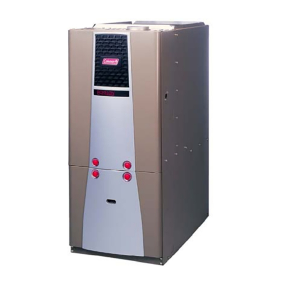
HIGH EFFICIENCY
TUBULAR HEAT EXCHANGER SERIES
MODELS: PV9*DH / FC9V*DH / FL9V*DH
(Two Stage Variable Speed Downflow/Horizontal)
CONTACT INFORMATION . . . . . . . . . . . . . . . . . . . . . . . . . . . . . . . . 1
USER'S INFORMATION . . . . . . . . . . . . . . . . . . . . . . . . . . . . . . . . . . . 1
SAFETY . . . . . . . . . . . . . . . . . . . . . . . . . . . . . . . . . . . . . . . . . . . . . . 1
FURNACE INSTALLATION . . . . . . . . . . . . . . . . . . . . . . . . . . . . . . . 2
HOW YOUR GAS FURNACE WORKS . . . . . . . . . . . . . . . . . . . . . . 3
START-UP AND SHUTDOWN INSTRUCTIONS . . . . . . . . . . . . . . . 3
Operating Instructions: . . . . . . . . . . . . . . . . . . . . . . . . . . . . . . . . . . 3
To Turn Off the Appliance: . . . . . . . . . . . . . . . . . . . . . . . . . . . . . . . 3
FURNACE USER MAINTENANCE . . . . . . . . . . . . . . . . . . . . . . . . . . 4
Blower Care . . . . . . . . . . . . . . . . . . . . . . . . . . . . . . . . . . . . . . . . . . 4
Air Filters . . . . . . . . . . . . . . . . . . . . . . . . . . . . . . . . . . . . . . . . . . . . 4
Removing Filters . . . . . . . . . . . . . . . . . . . . . . . . . . . . . . . . . . . . . . 4
Motor Lubrication . . . . . . . . . . . . . . . . . . . . . . . . . . . . . . . . . . . . . . 4
SERVICE AND MAINTENANCE MANUAL . . . . . . . . . . . . . . . . . . . . . 5
SAFETY SECTION . . . . . . . . . . . . . . . . . . . . . . . . . . . . . . . . . . . . . . 5
FURNACE MAINTENANCE SECTION . . . . . . . . . . . . . . . . . . . . . . . 5
FURNACE CLEANING SECTION . . . . . . . . . . . . . . . . . . . . . . . . . . 5
CONTACT INFORMATION
• Go to website at www.york.com click on "contact", then click on "contact form" and follow the instructions.
• Contact us by mail:
The manufacturer recommends that the user read all sec-
tions of this manual and keep the manual for future refer-
ence.
FIRE OR EXPLOSION HAZARD - Failure to follow
safety warnings exactly could result in serious injury,
death, or property damage.
- Do not store or use gasoline or other flammable
vapors and liquids in the vicinity of this or any
other appliance.
- WHAT TO DO IF YOU SMELL GAS:
•
Do not try to light any appliance.
•
Do not touch any electrical switch; do not use any
phone (including cell phone) in your building.
•
Leave the building immediately.
•
Immediately call your gas supplier from a neighbor's
phone. Follow the gas supplier's instructions.
•
If you cannot reach your gas supplier, call the fire
department.
- Installation and service must be performed by a
qualified installer, service agency or the gas sup-
plier.
TABLE OF CONTENTS
Burner Removal/Cleaning . . . . . . . . . . . . . . . . . . . . . . . . . . . . . . .5
Cleaning the Heat Exchanger . . . . . . . . . . . . . . . . . . . . . . . . . . . .5
Cleaning the Secondary Heat Exchanger . . . . . . . . . . . . . . . . . . .5
Cleaning the Vent / Air Intake System . . . . . . . . . . . . . . . . . . . . . .5
SEQUENCE OF OPERATION . . . . . . . . . . . . . . . . . . . . . . . . . . . . .5
CONTROL BOARD . . . . . . . . . . . . . . . . . . . . . . . . . . . . . . . . . . . . . .6
HEATING AIRFLOW . . . . . . . . . . . . . . . . . . . . . . . . . . . . . . . . . . . . .6
Heating Indoor Fan Off Delay . . . . . . . . . . . . . . . . . . . . . . . . . . . . .6
Continuous Blower Operation . . . . . . . . . . . . . . . . . . . . . . . . . . . .7
Delay Tap Selection . . . . . . . . . . . . . . . . . . . . . . . . . . . . . . . . . . . .7
Humidistat . . . . . . . . . . . . . . . . . . . . . . . . . . . . . . . . . . . . . . . . . . .7
Hot Surface Ignition System . . . . . . . . . . . . . . . . . . . . . . . . . . . . . .7
TROUBLESHOOTING . . . . . . . . . . . . . . . . . . . . . . . . . . . . . . . . . . .7
FURNACE CONTROL DIAGNOSTICS . . . . . . . . . . . . . . . . . . . . . . .8
DIAGNOSTIC FAULT CODE STORAGE AND RETRIEVAL . . . . . .8
REPLACEMENT PARTS LIST . . . . . . . . . . . . . . . . . . . . . . . . . . . . . .9
WIRING DIAGRAM . . . . . . . . . . . . . . . . . . . . . . . . . . . . . . . . . . . . . .12
LIMITED WARRANTY . . . . . . . . . . . . . . . . . . . . . . . . . . . . . . . . . . . .16
York International
Consumer Relations
5005 York Drive
Norman, OK 73069
SECTION I: USER'S INFORMATION
SAFETY
1.
The furnace area must be kept clear and free of combustible mate-
rials, gasoline and other flammable vapors and liquids.
2.
Insulating materials may be combustible. The furnace must be
kept free and clear of insulating materials. The furnace area must
be examined when installed in an attic or other insulated space or
when insulation is added to be sure that the insulation material has
been kept away from the furnace.
3.
The furnace needs air for combustion in order to operate properly
and safely. Do not block or obstruct air openings on the furnace,
air openings to the area where the furnace is installed, or spaces
around the furnace.
4.
Follow the instructions exactly as shown on the OPERATING
INSTRUCTION LABEL or the Start-up and Shutdown Instructions
on Page 3 of this manual when lighting the furnace or turning the
furnace off.
5.
Should the gas supply fail to shut off or if overheating occurs, shut
off the gas valve to the furnace before shutting off the electrical
supply.
6.
Do not use this furnace if any part has been under water. A flood-
damaged furnace is extremely dangerous. Attempts to use the fur-
nace can result in fire or explosion. A qualified service agency
should be contacted to inspect the furnace and replace all gas
controls, control system parts, electrical parts that have been wet
or the furnace if deemed necessary.
EFFICIENCY
RATING
CERTIFIED
Certified Quality
Management System
271042-UUM-A-0407
ISO 9001
Advertisement
Table of Contents

Summary of Contents for York International PV9DH Series
-
Page 1: Table Of Contents
FURNACE CLEANING SECTION ......5 CONTACT INFORMATION • Go to website at www.york.com click on “contact”, then click on “contact form” and follow the instructions. • Contact us by mail: York International Consumer Relations 5005 York Drive Norman, OK 73069 SECTION I: USER’S INFORMATION... -
Page 2: Instructions For Examining The Furnace Installation
271042-UUM-A-0407 INSTRUCTIONS FOR EXAMINING THE FURNACE INSTALLATION VENT PIPE It is the owner’s responsibility to ensure that an annual inspection of the CONDENSATE BLOWER entire heating portion of the unit is made by a qualified service agency. HOSE ACCESS Examine the heat exchanger, through a field installed access PANEL PFC CHOKE panel located on the supply air plenum. -
Page 3: How Your Gas Furnace Works
271042-UUM-A-0407 HOW YOUR GAS FURNACE WORKS To Turn Off the Appliance: Your furnace is a very easy appliance to take for granted. Season after Set the thermostat to lowest setting. season, it sits there in your home, keeping you warm and comfortable. Turn off all electric power to the appliance if service is to be per- For this reason, you may never have given much thought to the way formed. -
Page 4: Furnace User Maintenance
271042-UUM-A-0407 FURNACE USER MAINTENANCE Follow the instructions “HOW TO CLEAN YOUR FURNACE’S FIL- TER”. Reverse the procedure to reinstall filters. Follow the operating instructions to place appliance in operation. Before proceeding, be sure the area is well ventilated. Turn TABLE 1: Filter Sizes the thermostat OFF. -
Page 5: Service And Maintenance Manual
271042-UUM-A-0407 SECTION II: SERVICE AND MAINTENANCE Remove the screws that hold the burner box assembly to the vest MANUAL panel and remove the assembly. SAFETY SECTION Remove the vent pipe assembly, vent blower and condensate pan. The heat exchanger is now exposed. The following safety rules must be followed when servicing the With a long flexible wire brush, clean inside each tube at both the furnace. -
Page 6: Control Board
271042-UUM-A-0407 Call for 2nd Stage after 1st Stage is operating Cooling call satisfied • A call for 2nd Stage can be made by a 2-Stage thermostat, or by • The thermostat opens the R to Y and R to G circuits. the W2 delay timer on the furnace control. -
Page 7: Continuous Blower Operation
271042-UUM-A-0407 CONTINUOUS HEAT HI HEAT BLOWER FAN SPEED DEHUMIDISTAT DELAY DELAY OFF DELAY JUMPER JUMPER JUMPER JUMPER JUMPER VOLTAGE TERMINALS COOLING PROFILE JUMPER BLOWER SPEED JUMPERS FIGURE 7: Furnace Control Board Continuous Blower Operation Humidistat When a humidistat is installed in the system, the “Humidistat Installed?” The blower will run continuously whenever the wall thermostat fan switch is in the "ON"... -
Page 8: Furnace Control Diagnostics
271042-UUM-A-0407 FURNACE CONTROL DIAGNOSTICS 9 RED FLASHES: Indicates reversed line voltage polarity or grounding problem. Both heating and cooling operations will be affected. Check The furnace has built-in, self-diagnostic capability. If a system problem polarity at furnace and branch. Check furnace grounding. Check that occurs, a blinking LED shows a fault code. -
Page 9: Replacement Parts List
271042-UUM-A-0407 SECTION III: REPLACEMENT PARTS LIST 50,51 Unitary Products Group... - Page 10 271042-UUM-A-0407 ITEM DESCRIPTION ITEM DESCRIPTION MOTOR MOTOR/MODULE, ECM PROGRAMMED (Complete) MODULE, ECM PROGRAMMED (Module only) MISCELLANEOUS Motor, ECM (less ECM module) MOTOR, INDUCER ASSY RESTRICTOR, COMBUSTION BLWR ELECTRICAL GASKET, COMBUSTION BLOWER GASKET, CONDENSATE PAN SWITCH, LIMIT (INDUCER) GASKET, CONDENSING COIL CONTROL, HIGH LIMIT GASKET, GAS CONTROLS CONTROL, FLAME ROLL OUT...
- Page 11 3. Customer Service contact information. a. Click on the “Brand Links” button b. Click on the “Customer Service” button • You can contact us by mail. Just send a written request to: York International Consumer Relations 5005 York Drive Norman, OK 73069...
-
Page 12: Wiring Diagram
271042-UUM-A-0407 SECTION IV: WIRING DIAGRAM FIGURE 8: Wiring Diagram Unitary Products Group... - Page 13 271042-UUM-A-0407 NOTES Unitary Products Group...
- Page 14 271042-UUM-A-0407 NOTES Unitary Products Group...
- Page 15 271042-UUM-A-0407 NOTES Unitary Products Group...
-
Page 16: Limited Warranty
For Owner's Information PRODUCT MODEL. NO. ____________________ INSTALLATION DATE ______________________________ UNIT SERIAL NO. _________________________ INSTALLING DEALER ______________________________ Subject to change without notice. Printed in U.S.A. 271042-UUM-A-0407 Copyright © by York International Corp. 2007. All rights reserved. Supersedes: 167812-UUM-B-0706 Unitary 5005 Norman...
Need help?
Do you have a question about the PV9DH Series and is the answer not in the manual?
Questions and answers