Advertisement
Quick Links
LSC Lighting Systems
(Aust) Pty Ltd
ABN 21 090 801 675
7 University Place, Clayton
Victoria, 3168 Australia
Tel: +61 3 9561 5255
Fax: +61 3 9561 5277
Email: info@lsclighting.com.au
Web site: www.lsclighting.com.au
PowerGuard
POWER MONITORING SYSTEM
OPERATOR MANUAL
Version 1.3
May 2007
Designed and
Manufactured
in Australia
Advertisement

Summary of Contents for LSC PowerGuard
- Page 1 PowerGuard POWER MONITORING SYSTEM OPERATOR MANUAL Version 1.3 May 2007 LSC Lighting Systems (Aust) Pty Ltd ABN 21 090 801 675 7 University Place, Clayton Victoria, 3168 Australia Tel: +61 3 9561 5255 Designed and Fax: +61 3 9561 5277...
-
Page 2: Table Of Contents
Table Of Contents Page # Product Information Technical Specifications The System Components Power Distribution Chassis Power Guard Display Chassis Fan Unit Power Guard Operation Power Connections Appendix 1 Warranty and disclaimer Page 1 Power Guard Operator Manual Version 1.3 May 2007... -
Page 3: Product Information
The PowerGuard will analyse the voltage and current parameters of each phase of the incoming mains power, as well as measure the line frequency. An additional function for the PowerGuard is to monitor the temperature of the dimmer racks, when fitted into the TDS Dimming System. -
Page 4: Technical Specifications
Technical Specifications • Distribution Chassis: Input Supply 240 / 415VAC 3 Phase Input Connectors/ 5 Powerlocks Source and Drain (E, N, L1, L2 & L3) Current Rating: /400 Amps. Power Guard Voltage Monitor Rating: 240VAC per phase typical. (Maximum of 260VAC) Power Guard Current Monitor Rating: 240Amps per phase typical. -
Page 5: The System Components
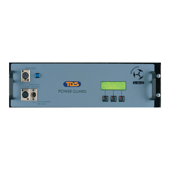
Display Monitor: PowerGuard The PowerGuard Monitor is the cabinet located on the top of the TDS and Delta products. The PowerGuard analog to digital electronics is located here and reads the signals from the Distribution Chassis. Conversions of these signals are made, calculations are done and the actual input power parameters are displayed on a 20 character x 4 line Liquid Crystal Display The display is backlit to allow viewing in dim light conditions. -
Page 6: Power Guard Operation
Power Guard Operation The PowerGuard Module user interface comprises the 20 character x 4 line LCD with integral backlight. Below it are three buttons each with an integral LED. The buttons and switches work together. The bottom line of the display will give menu choices. The LED in the button below the menu choice will glow indicating that the button will do something if pressed. - Page 7 Upon power up the display will show for approximately 3 seconds.: The TS Dimming System PowerGuard v1.20 L.S.C. Electronics Melbourne Australia After Power up, the display will show the SUMMARY screen: Screen 1 - SUMMARY This screen displays a summary of all the information available.
- Page 8 Screen 4 - TEMPERATURE This screen shows the current rack temperature and the fan status. It also allows you to go into the statistical menu or into preferences setup. Rack Temperature 20C Frequency 50.0Hz PREFS MORE NEXT The LEDs in the switches below “PREFS”, “MORE” and “NEXT” will illuminate. Pressing “NEXT”...
- Page 9 Pressing “RESET” will take you into the RESET Menu (Screen 11B). Page 8 Power Guard Operator Manual Version 1.3 May 2007...
- Page 10 Screen 8 - PREFS This screen displays the time, date and thresholds for the fans and allows you to go into the configuration menus. Set Preferences Time: 13:27:06 29/11 LAST SETTIME Pressing “SETTIME” will take you into the SETTIME Menu (Screen 9). Screen 9 - SETTIME This sceen allows the correct time and date to be set.
-
Page 11: Power Connections
The customer must however cover the freight costs to and from LSC Lighting Systems (Aust) Pty. Ltd. There are no user serviceable parts inside. Refer service to qualified personnel only.
Need help?
Do you have a question about the PowerGuard and is the answer not in the manual?
Questions and answers