
Summary of Contents for Cambridge Research Systems LiveTrack-AV
- Page 1 LiveTrack-AV for fMRI Installation Manual Version R03 June 2015 Cambridge Research Systems Limited 80 Riverside Estate Sir Thomas Longley Road Rochester Kent ME2 4BH England www.crsltd.com...
- Page 2 LiveTrack AV for fMRI installation manual Version Date Changed by: Description of Changes 1.0 1/6/2012 E.Wallington First issue R02 September, Updated text and images to firmware 2014 version VET26000. Added example of video feed. R03 June, 2015 Updated firmware version VET26110. Version R02...
-
Page 3: Table Of Contents
LiveTrack AV for fMRI installation manual Contents Parts List (items for use in magnet room) ...................... 3 Parts List (items for use OUTSIDE magnet room) ................... 5 Introduction .................................. 7 Overview .................................. 7 How it works .................................. 8 Image Capture ................................ 8 Image Processing .............................. 8 USB interfaces ................................ 8 Synchronisation ................................. 8 Installation .................................. 9 Filter box .................................. 9 Power supply ................................ 9 Livetrack .................................. 9 Camera and illuminator ............................ 1 0 Setting up the control Computer . -
Page 4: Parts List (Items For Use In Magnet Room)
LiveTrack AV for fMRI installation manual Parts List (items for use in magnet room) Headcoil mount The head-coil mirror mount fits the camera to the head-coil (specific to particular head-coil and scanner, example on the left). The camera is mounted on the mirror mount using short rod (picture on right). MRI compatible camera with 16 mm lens This is a type B device for use in the patient environment. Version R02... - Page 5 LiveTrack AV for fMRI installation manual Camera cable This cable extends the camera cable to connect to the filter box. Pupil calibration stick The pupil calibration stick is used to calibrate the pupil area Version R02...
-
Page 6: Parts List (Items For Use Outside Magnet Room)
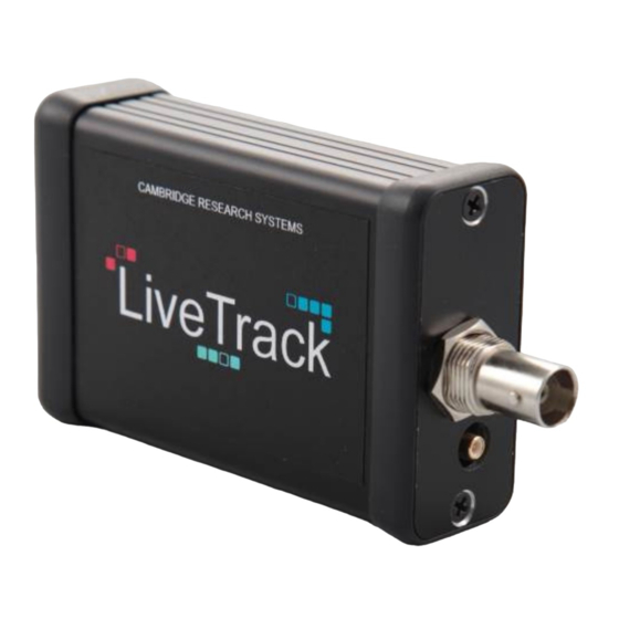
LiveTrack AV for fMRI installation manual Parts List (items for use OUTSIDE magnet room) Camera filter box The filter box MUST be fitted into the penetration panel of the magnet room, from the control room side. LiveTrack DSP box– This unit processes the analogue video signal and does the actual eyetracking. This small box connects between the camera filter box and the host computer. Camera power supply– This power supply connects to filter box and should be plugged in to a suitable wall socket in the control room. This is a special low leakage current power supply that complies with EN60601. Version R02... - Page 7 LiveTrack AV for fMRI installation manual BNC video lead connects from the filter box to the LiveTrack DSP box. Trigger input lead (BNC to SMA) Connects from the stimulus generator to the LiveTrack DSP box. USB cable Connects from the LiveTrack DSP box to the host computer. Instructions The printed version of these instructions Version R02...
-
Page 8: Introduction
LiveTrack AV for fMRI installation manual Introduction Overview LiveTrack-AV for fMRI provides a 60Hz eye-tracking solution for experiments utilising an MRI scanner. A miniature shielded video camera, with integrated 940nm NIR illumination source, plus a bespoke mirror mount, enable eye-tracking without distracting from the visual stimuli. The camera connects via a filter box that must be permanently installed in the penetration panel of the magnet room. The filter box provides several vital functions: It prevents interference coupling into the scanner. It prevents RF leakage from the scanner. It provides safety isolation of the camera (EN60601 type B) from the computer equipment in the magnet room (which will have higher leakage currents not permitted in the “patient environment”). Consult your maintenance organisation for installation of the filter box in the penetration panel. In the AV for fMRI version, there is one video camera and one or two DSP boxes per eye (depending on the host operating system). So a full system would comprise two video cameras and two or four DSP boxes. The DSP box is located in the control room and connects to the host computer via a USB 2.0 connection. No power supply is needed for the DSP box, it receives its power from the host computer via the USB connection. The host computer is only used for stimulation, control and to receive results, the actual eye- tracking is done by the DSP box. Version R02... -
Page 9: How It Works
LiveTrack AV for fMRI installation manual How it works Image Capture The 940nm LED light is embedded in the camera housing. The short distance between the lens and LED is chosen in order to avoid undesired shadowing effects. The image of the eye formed by the lens is captured by a built-in CMOS image sensor. Image Processing The LiveTrack device takes the frame and subjects it to on-board image processing to locate the Pupil and glint (the glint is a first Purkinje Image). USB interfaces The USB connection is configurable, and provides three different interfaces to the host computer over the single USB lead. It is compatible with all major operating systems. 1) Mass storage interface (USB MSD). This is used for initial configuration of the eye- tracker and for system upgrades. 2) HID class interface (USB HID). The LiveTrack emulates a Human Interface Device and requires no additional driver 3) Video feed (USB UVC). Used to align the camera to the subject. By default HID and UVC interfaces are both turn on. The MSD interface can be access by pressing button through the little hole on the side of the LiveTrack DSP box. Synchronisation LiveTrack has a trigger input, which should be connected to a suitable output of the stimulus generator. This enables the eye-tracking results to be synchronised perfectly with the experiment. Version R02... -
Page 10: Installation
LiveTrack AV for fMRI installation manual Installation Filter box The filter box includes a low pass filter that suppresses frequencies higher than 1 MHz with over 100 dB. This filter prevents damage and interferences caused by the high frequency signals of the MR scanner. In addition, the filter box includes an optical isolation of the video signals. In that way a full separation of the MRI equipment from the external power network is guaranteed. The filter box should be screwed onto the penetration panel board by means of the feed through camera connector. A 12 mm through hole in the penetration panel is required. • The camera connector is guided through this hole from the control room side. • The camera connector provides the ground connection to the shielding of the MR • cabinet. The penetration panel around the camera connector must therefore provide good electrical contact. The area should therefore be free from paint or oxidisation and the clamping nuts on the connector must be done up tight. Power supply The camera power supply should be connected to a suitable wall socket IN THE CONTROL ROOM near to the penetration panel. DO NOT locate the power supply in magnet room. Plug the low voltage DC lead from the power supply into the filter box (see below). The power for the camera is then transmitted via the video cable. Next to the video connector is a green LED which shines when the device is powered. Livetrack Connect the LiveTrack DSP box to the VIDEO OUT of the filter box with the video BNC lead. The USB lead goes from LiveTrack to a spare USB socket on the host computer, but see the section on setting up the host computer before attaching this lead. Connect the trigger lead from LiveTrack to a TTL level trigger output from the stimulus generator (use the trig out BNC if using a Cambridge Reseach Systems Visage or Bits# system. Note: We recommend connecting the isolated scanner trigger to the stimulus generator, rather than to LiveTrack, as this provides the lowest latency for control of the stimulus. Version R02... -
Page 11: Camera And Illuminator
LiveTrack AV for fMRI installation manual Camera and illuminator Fix the camera(s) into the head-coil mount whilst in the control room. Do not take screwdrivers into the magnet room for obvious reasons!! The camera comes fitted with a 16 mm lens for tracking. If you wish to use the camera with a wide angle lens to capture a larger part of the face (no eye tracking) short focal length lenses are available. The camera then mounts with two small brass screws typically on to an arm on the head-coil mount. Once the camera is fixed to the arm, then fix the arm on to the head-coil mount. Make sure the IR-LED is on the lateral side of the camera. This means that if you change sides with the camera, you will have to turn the camera on the arm. You can then slowly take the assembly into the magnet room. The head-coil mount typically clips or clamps on to the head-coil (depending on the version). Then attach the camera cable to the short pre-attached cable on the camera. The device is connected to the filter box via this extension cable which must be plugged into the “MR CAM Signal IN” connector. This connector should be the only part of the filter box on the magnet room side of the penetration panel. The powering of the camera and the LED is arranged via the filter box. The camera/LED is connected to the filter box with the shielded camera connection cable which includes the power and the signal lines. Setting up the control Computer The LiveTrack DSP box is setup from the factory with default setting that should not need to be changed. However, you can access the internal memory of the DSP to download documentation and example scripts. To access the “mass storage” interface, hold the button pressed for a few seconds whilst the USB lead is connected (with a small screwdriver or unfolded paper clip). Connect this way the first time that LiveTrack is used. The Image above demonstrates the location of the button on a LiveTrack AV system. With a laptop computer, you may receive a message that there is insufficient power available for the LiveTrack device. LiveTrack requires 500mA to be available from the USB connection. In this case try (in this order): 1. A different USB socket on the laptop. 2. Connecting the laptop to its mains charger. 3. Or finally connect LiveTrack by a powered USB hub. Version R02... -
Page 12: Configuring Livetrack And Interfaces
LiveTrack AV for fMRI installation manual Configuring LiveTrack and interfaces By default HID and UVC interface are turned on. It is not recommended to change this setting but it is possible to set which USB interfaces are active by editing the Firmware.xml file located on the LiveTrack device. You can edit this file with any suitable text editor (for instance Notepad on Windows). The rest of the settings are parameters for the tracking algorithm and should not be changed. Once you have finished editing the LiveTrack.xml file, exit the text editor (saving the file when prompted). The status LED will light up to indicate activity (the drive is rather slow, compared to other USB drives you might use). Once the status light has gone out, eject the drive, then re-boot the LiveTrack box by disconnecting the USB lead, waiting for 2 seconds, then reconnecting it. Do not press the push button this time. When editing, saving or deleting files on the LiveTrack system, an orange light next to the USB input will be illuminated. While in Mass Storage Device-mode the device should only ever be unplugged or reset if this light is off. Be sure to use the eject function in your operating system before disconnecting the device. Any cycling of power while the light is illuminated could result in corrupted data. Version R02... -
Page 13: Aligning The Video Camera
LiveTrack AV for fMRI installation manual Aligning the video camera Viewing the video image The LiveTrack video feed uses the USB video device class (UVC). This standard is also used by many web cameras and it is natively supported by all major operating systems. The video feed can be viewed with numerous applications. To mention a few: AMCap, VLC player, WebcamViewer or the Camera.exe application located on the MSD drive of the DSP box. The video feed can also be captured in MATLAB using either MATLAB’s own add-on Image Acquisition Toolbox or the open source Psychtoolbox. Please consult the respective latest available documentation for setup instructions. The intensity of the LED light can be adjusted by means of a potentiometer at the filter box. For optimal tracking it is recommended to have a camera-to-eye distance between 100 and 120 mm. Make sure the camera is located between 100 and 120 mm from the eye. Any other distance will make the eye tracking unreliable. Focusing the video image If the eye is blurry then the image can be adjusted by twisting the lens to adjust the focus. When focusing, the important feature is the pupil. Do not make the mistake of trying to focus on the eye-lashes, as these are in quite different focal planes to the pupil and glint. A convenient way of adjusting the focus is to get the glint as small as possible (less blur). Another focusing clue that can be used is the structure visible in the iris. Version R02... - Page 14 LiveTrack AV for fMRI installation manual The images in the near infra-red do look quite “soft” compared to visible light images. This is quite normal. Once focus has been achieved (by default the pupil fitting video overlay is on), a white ellipse should be shown over the pupil iris boundary. If set, there will also be a grey cross on the glint. These indicate that tracking has successfully locked on. Example of a good image with pupil fit and glint overlay (ellipse and crosshair): Example of a bad image with missing pupil fit and glint overlay (reason: camera located too far from the eye): Example of a bad image with bad pupil fit (reason: camera located too far from the eye): Version R02...
-
Page 15: Safety
LiveTrack AV for fMRI installation manual Safety The MRI scanner should only be used by suitable qualified personnel aware of the risks involved. National regulations and guidelines should be followed. Follow all safety instructions from the MRI scanner manufacturer. Life support applications LiveTrack should NOT be used in situations where failure of the device, or failure of eye- tracking, would constitute a hazard. It is designed for research applications only, and like any other regular electronic device could fail at any time, without warning. Photo Sensitive Epilepsy Any system capable of creating flashing images can potentially induce photo sensitive epilepsy in susceptible individuals. Experiment design should take this risk into account. http://www.hardingfpa.co.uk/resources/photosensitive-epilepsy-pse/ Cleaning Clean external components of LiveTrack with a damp cloth only. Do NOT allow fluids to enter any of the LiveTrack components. Do not sterilise in an autoclave. Take special care when cleaning the camera's lens. Use only a clean lens tissue or lens brush. Version R02... -
Page 16: Servicing
LiveTrack AV for fMRI installation manual The camera is not specially protected against splash water. It should only be used in dry environments. If moisture is entrapped into the housing a short circuit can occur leading to a damage of the electronics. Servicing DO NOT ATTEMPT TO DISMANTLE LiveTrack or the camera. It contains no user serviceable components, refer all servicing to Cambridge Research Systems. Optical Hazard Do not shine the LED directly into the eye from a small distance. We recommend to use the lowest power required for tracking and to keep a distance of 10 cm to the eye. Disconnect from mains whenever it is not in use. Radio-frequency leakage and electrical safety bonding The camera housing must be electrically connected to the shielding of the magnet room. The filter box must be permanently installed in the penetration panel to achieve this grounding. Failure to do this would compromise the safety of the patient environment and exposes those outside of the scanner to risk from radio-frequency fields. Electrical safety The LiveTrack-AV for fMRI system is supplied with a EN60601 approved power supply for use with the filter box and MRC camera. Do not substitute a different power supply as this will invalidate the safety approval of the system. Do not connect the power supply to a voltage or frequency outside of its stated range. Magnet hazards Due to the metallic housing the camera can be attracted and accelerated by the MRI scanner during a quench of the super-conducting magnets. Therefore the camera should be mounted to a fixed object, whenever it is brought into the magnet room. The camera should not be moved fast in the environment of the MRI scanner. The movement can generate eddy currents leading to unforeseeable forces. A stable attachment is required, whenever the camera is mounted above a person to make sure, that the camera cannot fall down onto this person. Only the camera / head-coil mount assembly and camera cable are safe for use in the magnet room. Version R02... -
Page 17: Radio-Frequency Heating
LiveTrack AV for fMRI installation manual DO NOT take the DSP box, filter box, or power supply into the magnet room. These items are MR-unsafe. Radio-frequency heating The metallic housing and the cables of the camera can absorb energy from the electromagnetic fields of the MRI scanner. This absorption can lead to heating of the housing. The heating level depends on the orientation of the camera and its cables relative to the MRI scanner and on the imaging sequences used. Therefore the temperature of the camera should be checked before it is touched and no inflammable objects should be attached to the camera. The camera is tested with different orientations of housing and cables. However, it is not possible to check all possible situations which might occur in different applications. The cables can act as antennas and disturb the sensitively adjusted fields of the MRI scanner. If interferences of MR images or video images occur, one should try to change the directions of the cables. Radio-frequency burns Whenever metallic parts are used in an MRI scanner there is a residual risk of an electric discharge from this part to the human body. Do not to place the device closer than 10 cm to the subject or the user. The risk of an electric discharge can be further reduced if the connection cable is guided on a direct way (without loops and without crossing the middle axis) out of the bore. Do not drop the camera The device is equipped with sensitive optical components. It should not be dropped from larger heights. The filter box is only suitable for the Camera “12M-i” with integrated LED. Connecting the standard 12M or CS camera to the filter box will destroy the integrated electronics. Contact Cambridge Research Systems Limited Telephone: +44 1634 720707 Website: www.crsltd.com Version R02... - Page 18 LiveTrack AV for fMRI installation manual 80 Riverside, Sir Thomas Longley Road, Rochester, Kent United Kingdom ME2 4BH Version R02...
Need help?
Do you have a question about the LiveTrack-AV and is the answer not in the manual?
Questions and answers