Table of Contents
Advertisement
Quick Links
General Description
The Evaluation Kit epc901 is a fully assembled and tested system
for the evaluation of the the epc901 line imager. The Evaluation Kit
consists of an epc901 camera module, a mainboard, cables and
software.
The "Evaluation" main section is equipped with a STM32 ARM Cor-
tex micro controller. This section provides a powerful and flexible
development environment for the design engineer. It supports all
the epc901 line imager camera module.
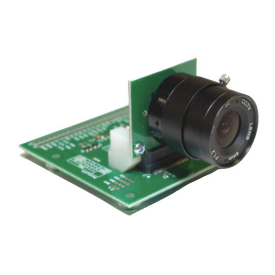
The camera module comes equipped with an epc901 line imager
chip. The module includes a complete lens system and a camera
cable connects it to the mainboard, allowing a flexible and conve-
nient placement in a lab setup.
System overview
➀
epc901 camera module connector
➁
Evaluation / application switch
➂
STM32 ARM Cortex controller
➃
USB connector
➄
Switch USB or external supply
➅
Dip switch and LED bank application
➆
10 pin debug connector
Figure 1: epc901 camera module
Figure 3: Field of view of the camera: 1'912 x 30 mm at 1m
(87.7° x 1.7° at infinity)
© 2015 ESPROS Photonics Corporation
Characteristics subject to change without notice
Features
■ Fully functional line imager camera 1'024x1 pixel with epc901
line imager chip.
■ Application software with graphical user interface to operate the
epc901 chip of the camera.
■ Possibility to store and reload operating configurations.
■ Functionality for logging measurement data on PC.
■ Complete development system for epc901 line imagers.
■ PC connectivity and power supply by USB.
■ Corresponding user software (PC/Mac) with visualization and
logging features as part of the camera system.
Purpose
■ Demonstration system for epc's line imager technology chips.
■ Reference application for evaluation and design engineers.
Pixel 1'023
Pixel 0
Figure 4: The main dialog of the graphical user interface
1 / 28
Manual – epc901 Evaluation Kit
5
4
7
3
Figure 2: Mainboard V2.0
Manual_epc901_EvalKit-V1.2
6
1
2
www.espros.com
Advertisement
Table of Contents

Summary of Contents for ESPROS epc901
-
Page 1: General Description
The Evaluation Kit epc901 is a fully assembled and tested system ■ Fully functional line imager camera 1'024x1 pixel with epc901 for the evaluation of the the epc901 line imager. The Evaluation Kit line imager chip. consists of an epc901 camera module, a mainboard, cables and ■... - Page 2 THIS CAMERA COMES WITH FOCUSED OPTICS. Do not touch the lens. Do not twist or turn the lens. Otherwise a degradation of the measurement occurs. © 2015 ESPROS Photonics Corporation 2 / 28 Manual_epc901_EvalKit-V1.2 Characteristics subject to change without notice...
-
Page 3: Table Of Contents
Table of Contents General Description......................................1 Features..........................................1 Purpose..........................................1 System overview........................................1 1. General overview of the epc901 Evaluation Kit............................4 1.1. Ordering information....................................4 1.2. Scope of delivery....................................4 1.3. System requirements.....................................5 1.4. Technical data epc901 camera................................5 1.5. Technical data Evaluation Kit Mainboard..............................5 1.6. Support and technical contact................................5 2. -
Page 4: General Overview Of The Epc901 Evaluation Kit
1. General overview of the epc901 Evaluation Kit The chapter gives an overview about the epc901 Evaluation Kit, which is based on this mainboard, their components and the technical data of the mainboard. 1.1. Ordering information Part number Order information... -
Page 5: System Requirements
RoHS Fulfills 2002/95/EC Table 4: Technical data mainboard 1.6. Support and technical contact If you need more information, please contact us at info@espros.com. © 2015 ESPROS Photonics Corporation 5 / 28 Manual_epc901_EvalKit-V1.2 Characteristics subject to change without notice www.espros.com... -
Page 6: Hardware
PC USB interface is not capable of delivering the necessary power (ca. 1'000mA). ■ The “evaluation system” section supports and gives access to the full functionality epc901 device. □ Connects video output and 2-wire bus. -
Page 7: Epc901 Chip
2.3. epc901 camera module (epc901 evaluation hardware) As a epc901 camera, epc offers a chip carrier board and an evaluation board for an easy test setup. It simplifies the use of epc's 1024x1pixel CCD line sensor. The Chip Carrier Board holds the chip and offers an easy lens mount possibility. -
Page 8: Epc901 Chip Carrier Board V2
2.4. epc901 Chip Carrier Board V2 2.4.1. Schematics Figure 10: Schematics of the epc901 Chip Carrier Board V2 2.4.2. Board layout 2 holes ∅ 2.10mm 2 holes ∅ 2.20mm 22.00 Figure 11: Layout of the Chip Carrier Board V2 Pin1 Figure 12: Assembly of the Chip Carrier Board V2:top / bottom / dimensions ©... -
Page 9: Pcb Card Connector
Figure 13 and Figure 14 show possible card connectors for interfacing the chip carrier board with the user's application board e.g. SAMTEC MEC6-130-02-L-DV-A / -RA1 Figure 13: Vertical mount mini-edge card connector Figure 14: Right angle mini-card connector (Source: Samtec) © 2015 ESPROS Photonics Corporation 9 / 28 Manual_epc901_EvalKit-V1.2 Characteristics subject to change without notice... -
Page 10: Epc901 Evaluation Board V2
2.5. epc901 Evaluation Board V2 2.6. Schematics Figure 15: Schematics of the epc901 Evaluation Board V2 © 2015 ESPROS Photonics Corporation 10 / 28 Manual_epc901_EvalKit-V1.2 Characteristics subject to change without notice www.espros.com... -
Page 11: Board Layout
2.6.1. Board layout Figure 16: Layout of the Evaluation Board V2 Figure 17: Assembly of the Evaluation Board V2: top / bottom incl. Dimensions © 2015 ESPROS Photonics Corporation 11 / 28 Manual_epc901_EvalKit-V1.2 Characteristics subject to change without notice www.espros.com... -
Page 12: Set-Up
Figure 18: Minimal set-up with 3V supply (standalone, default configuration) Notes: Low power operation: use external 3V and 5V supply, refer to the epc901 datasheet. Change the configuration of the epc901: use respective I2C commands or solder zero-ohm resistors according to the table printed on the Evaluation Board. -
Page 13: Evaluation Kit Mainboard - V2.0
2.7. Evaluation Kit Mainboard – V2.0 2.7.1. Schematics © 2015 ESPROS Photonics Corporation 13 / 28 Manual_epc901_EvalKit-V1.2 Characteristics subject to change without notice www.espros.com... - Page 14 © 2015 ESPROS Photonics Corporation 14 / 28 Manual_epc901_EvalKit-V1.2 Characteristics subject to change without notice www.espros.com...
-
Page 15: Assembly & Part List
2.8. Assembly & part list Default jumper setting Figure 22: Assembly and default jumper setting © 2015 ESPROS Photonics Corporation 15 / 28 Manual_epc901_EvalKit-V1.2 Characteristics subject to change without notice www.espros.com... - Page 16 Header 5X2 Header, 5-Pin, Dual row J7, J8, J11 Header 2X2 Header, 2-Pin, Dual row Dubox 2x6 Header, 6-Pin, Dual row Table 5: Part list © 2015 ESPROS Photonics Corporation 16 / 28 Manual_epc901_EvalKit-V1.2 Characteristics subject to change without notice www.espros.com...
-
Page 17: Mainboard Overview
The mainboard is divided into two areas with independent functionality. In the „Evaluation“ area (the upper part of the board) is the “epc901 evaluation system” It contains the USB interface, the main-micropro - cessor of the evaluation system. There are also communication and I/O lines on the 3.3V level to the epc901device. There are other parts which are not used for this application. -
Page 18: Epc901 Camera Connector J4
With the selection switch SW2, the working area of the mainboard can be selected: ■ In the upper position, the “Evaluation” area is active for the epc901 evaluation system. The camera is operated and accessed by the Evaluation Kit application software on the user's computer. -
Page 19: Header J7 (Boot Option)
TRACESWO if async trace is enabled TRST JTAG Test Reset JTAG Test Data input PA15 RESET Debug environment reset NRST Table 9: JTAG / SWD connector © 2015 ESPROS Photonics Corporation 19 / 28 Manual_epc901_EvalKit-V1.2 Characteristics subject to change without notice www.espros.com... -
Page 20: Stm32 Debug (J10)
The STM32 reset button S2 is connected to the STM32's NRST input pin. A low level (pressed button) causes a system reset of the con- troller (for more information refer to STM32F207 reference manual; see chapter 6.1: Related documents). Note that the reset signal is only connected to the STM32 controller. © 2015 ESPROS Photonics Corporation 20 / 28 Manual_epc901_EvalKit-V1.2 Characteristics subject to change without notice www.espros.com... -
Page 21: Software Setup & Installation
Start the application with the link “epc600_610_901_Evaluation_Kit” that has been added to your program shortcut menu. Disconnect the USB cable before attaching a camera module and proceed with chapter 3.2. Running the epc901 application. © 2015 ESPROS Photonics Corporation 21 / 28 Manual_epc901_EvalKit-V1.2... -
Page 22: Sw Installation On Mac
Connect the camera module to the cable and the other side of the cable to the mainboard. Set the operation switch SW2 to “Evaluation” (see Figure 27). This will set the evaluation system into the epc901 evaluation mode and al- lows for the operation through the application software on the computer. - Page 23 Start the application software on your computer and press the “Connect” button on your main screen to connect the application software to the evaluation system. Press the button “Start” to start the evaluation software. Refer to next chapter 4. Software “epc901 evaluation system” and user interface for detailed operating instructions. © 2015 ESPROS Photonics Corporation 23 / 28 Manual_epc901_EvalKit-V1.2...
-
Page 24: Software "Epc901 Evaluation System" And User Interface
4.1. Overview This chapter describes the epc901 Evaluation Kit software (SW) and graphical user interface (GUI). The user interface is designed as a di - alog based application. The software operates the epc901 camera module, reads the data delivered by the module and allows for data log- ging. -
Page 25: Basic Operation
The Evaluation Kit requires firmware that runs on the ARM controller. This firmware configures the chip, performs the measurements, cal - culates the result values, interfaces to the computer software and much more. As the development around the epc901 device is ongoing, there will be regular updates of this software. -
Page 26: Log Dialog
The firmware is on the CD enclosed in the camera package. 4.1.5. Log dialog This function allows data logging for offline analysis of epc901 chip read-out data. The data stream can be collected either by number of measurement counts or by a logging time. -
Page 27: Maintenance And Disposal
6. Addendum 6.1. Related documents ■ Datasheet epc901, ESPROS photonics corp., 2014 ■ STM32F205xx, STM32F207xx, STM32F215xx and STM32F217xx advanced ARM-based 32-bit MCUs, Reference manual, ST Micro- electronics corp., 2011 6.2. -
Page 28: Important Notice
IMPORTANT NOTICE Information furnished by ESPROS Photonics AG (epc) is believed to be accurate and reliable. However, no responsibility is assumed for its use. ESPROS Photonics AG and its subsidiaries (epc) reserve the right to make corrections, modifications, enhancements, improvements, and other changes to its products and services at any time and to discontinue any product or service without notice.
Need help?
Do you have a question about the epc901 and is the answer not in the manual?
Questions and answers