Advertisement
Table of Contents
Applied Machines: C287/C227
COLOR MFP: 28 ppm/22 ppm
Product Code: A797/A798
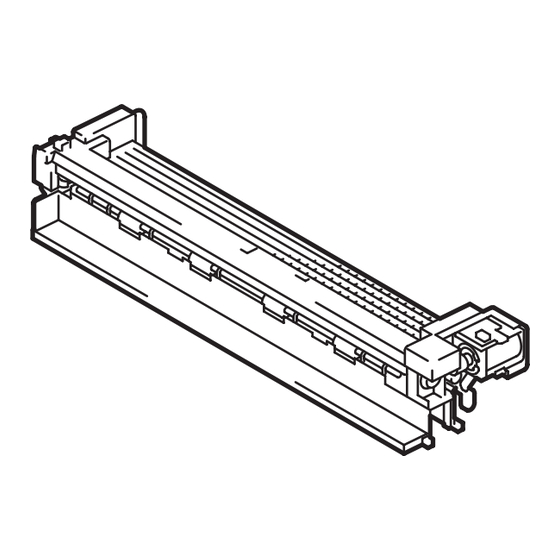
1. Accessory parts
No.
Name
1. 2nd paper exit
unit
2. Gear
3. Belt
4. Wire saddle
5. Screw
6. Installation
manual
Keep this bag away from babies and
children. Do not use in cribs, beds,
carriages, or playpens.
The thin film may cling to nose and
mouth and prevent breathing. This bag is
not a toy.
MK-603
INSTALLATION MANUAL
Shape
Q'ty
1
1
1
2
2
1 set
Mount kit
Note:
• This manual provides the illustrations of the
accessory parts and machine that may be
slightly different in shape from yours. In that
case, instead of the illustrations, use the
appearance of your machine to follow the
installation procedure. This does not cause any
significant change or problem with the proce-
dure.
• The Mount Kit MK-603 is required to use the
Finisher FS-534SD/FS-534/FS-533 or the Job
Separator JS-506. Mount the MK-603 before
installing the finishing option.
2. Installation procedures
(1) Turn OFF the power switch and unplug the
power cord from the power outlet.
(2) Open the right door.
(3) Remove the cover shown in the illustration. (One
screw)
(4) Remove the cover shown in the illustration. (One
screw)
E-1
A8D9-9550-00
Advertisement
Table of Contents

Related Manuals for Konica Minolta MK-603

Summary of Contents for Konica Minolta MK-603
- Page 1 This does not cause any significant change or problem with the proce- dure. • The Mount Kit MK-603 is required to use the Finisher FS-534SD/FS-534/FS-533 or the Job 2. Gear Separator JS-506. Mount the MK-603 before installing the finishing option.
- Page 2 (5) Disconnect the connector. (8) Remove the belt. Note: Discard the removed belt. (6) Remove the C-clip and remove the front paper exit unit. Note: (9) Remove the C-clip and remove the pulley. Reattach the removed C-clip to the front paper exit Note: unit to prevent it from being lost.
- Page 3 (11) Install the 2nd paper exit unit on the paper exit (14) Remove the cover shown in the illustration. unit by fitting the two protrusions into the holes. (One screw) Note: Install the 2nd paper exit unit while pressing the guide down by hand.
- Page 4 (17) Conduct the following procedure to reinstall the (18) Attach the two supplied wire saddle. paper exit unit to the main body. a) Tilt the paper exit unit to insert it into the main body. (19) Connect the connectors and route the har- nesses inside the wire saddles.
Need help?
Do you have a question about the MK-603 and is the answer not in the manual?
Questions and answers