Table of Contents
Advertisement
Quick Links
040910-01
Operating Instructions
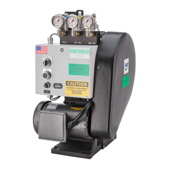
For RIX Compressor Family: 2PS-15
Models: 2PS-15-115, 2PS-15-220 & 2PS-15-230
Rix Industries
2 Stage, Oil-Less
Air-Cooled
Oxygen Compressor
This manual, including information and products referenced herein, to be provided by Seller
("Products") are subject to U.S. export control laws and will not be resold, re-exported, or
retransferred, directly or indirectly, to any person in violation of U.S. Export Administration
Regulations.
4900 Industrial Way, Benicia, CA 94510 | www.rixindustries.com | 707.747.5900
Advertisement
Table of Contents

Subscribe to Our Youtube Channel
Related Manuals for RIX Industries 2PS-15-115


Summary of Contents for RIX Industries 2PS-15-115
- Page 1 040910-01 Operating Instructions For RIX Compressor Family: 2PS-15 Models: 2PS-15-115, 2PS-15-220 & 2PS-15-230 Rix Industries 2 Stage, Oil-Less Air-Cooled Oxygen Compressor This manual, including information and products referenced herein, to be provided by Seller (“Products”) are subject to U.S. export control laws and will not be resold, re-exported, or retransferred, directly or indirectly, to any person in violation of U.S.
-
Page 2: Revision History
10/14/21 See ECO-011231 10/26/21 Discharge RV Setpoint Correction Specification changes for new viii, 6, 8, 01/21/22 minimum suction pressure, new Appendix interface drawing ii, iii, 9, 11, 19- Addition of Sections 5.9 and 7.12 04/13/22 RIX Industries 040910-01 Page i... -
Page 3: Table Of Contents
Chapter 6 - Troubleshooting ................Error! Bookmark not defined. Compressor Symptoms ............................ 12 Chapter 7 - Corrective Maintenance ..........................14 Introduction................................14 Gas Leak Check ..............................14 Cylinder Heads ..............................14 Compressor Valves ............................15 Compression Cylinders ............................ 16 Compression Rings ............................16 RIX Industries 040910-01 Page ii... - Page 4 Piston Assembly ..............................17 Main Bearings ..............................18 Piston to Head Clearance ..........................18 7.10 Clearances & Tolerances ..........................19 7.11 Spare Parts ................................19 Appendix ....................................21 RIX Industries 040910-01 Page iii...
-
Page 5: Parts, Service & Technical Support
Parts, Service & Technical Support Manufacturer: RIX Industries 4900 Industrial Way Benicia, California 94510 USA Phone: 707-747-5900 Fax: 707-747-9200 Parts Fax: 707-748-0398 www.rixindustries.com/request-spare-parts/ Parts Dept. Hours: 6:30-15:30 PST Compressor model and serial number must be provided with all inquiries. Compressor Model Family... -
Page 6: Safety Precautions
This symbol means if precaution is not taken, it may cause bodily injury or damage to the machine. 7. Do not touch cylinder heads or discharge gas lines from the heads up to the heat exchanger inlets. These are hot and can cause serious burns. RIX Industries 040910-01 Page v... -
Page 7: Oxygen Compatibility Requirements
CGA procedures. RIX recommends that all maintenance be performed by qualified personnel with full knowledge of oxygen equipment handling procedures and the potential hazards of contamination. RIX further recommends returning the compressor package to RIX Industries or RIX-approved service center when servicing or repairing this compressor package. -
Page 8: Compressor Warranty
H. Normal Wearing parts are defined, but not limited to the following: Seals, Gaskets, O-rings, piston rings and riders, bulbs, fuses, and anti-corrosion devices such as zincs. RIX Industries reserves the right to evaluate these items for material workmanship and defects on a case-by-case basis. -
Page 9: Compressor Specifications
Compressor Specifications This document is valid for the following RIX compressor(s): 2PS-15—models 2PS-15-115, 2PS-15-220 & 2PS-15-230 Cylinder Size(s): 1 ¼” & ½” Design Specifications Stroke Length: 2” Motor Power: ¾ HP Rotation: Clockwise from flywheel side Nominal Compressor Speed: 127 RPM... -
Page 10: Chapter 1 - Compressor Overview
A small amount of inert piston ring dust will pass into the gas stream; this can be filtered out if desired. RIX Industries 040910-01 Page 1... -
Page 11: Crankcase Lubrication
Crankcase Lubrication This oil-less compressor utilizes sealed bearings. Oil-less compressors contain absolutely no oil within the whole compressor package removing the likelihood of any oil carry over, thus eliminating contamination. RIX Industries 040910-01 Page 2... -
Page 12: Chapter 2 - Installation
DANGER Do not install ball valves in either suction or discharge plumbing. If closed quickly, these valves can cause fire and/or explosion. RIX Industries 040910-01 Page 3... -
Page 13: Electrical Connections
After extended storage, or if stored without climate control, the compressor heads and valves should be removed and inspected for corrosion. Bearings should also be inspected and/or replaced and the relief valves should be cleaned, rebuilt, and/or replaced. RIX Industries 040910-01 Page 4... -
Page 14: Chapter 3 - Start-Up & Operating Parameters
User’s downstream plumbing. Gas temperature will also rise in conjunction with the compression ratio of each stage. All shutdown devices and control logic should be tested before the system is put into autonomous operation. RIX Industries 040910-01 Page 5... -
Page 15: Normal Operating Conditions
It is recommended that the Service Log in the appendix of this manual be used to note operating pressures, temperatures, and maintenance done at hours of compressor operation. If pressures do not fall near the above stated values, or vary from your historical pressures, see Chapter 6 – Troubleshooting for corrective action. RIX Industries 040910-01 Page 6... -
Page 16: Chapter 4 - Control System
"closed" point of the switch at which point the compressor will restart. To manually stop the unit, switch the HOA switch to the OFF position. RIX Industries 040910-01 Page 7... -
Page 17: Control Logic Description
Relief Valve Suction 75 psig Relieve excess Device Stage Set Point Function pressure build up Interstage 700 psig Discharge 2200 psig Motor Overload Motor FLA Shutoff Pressure Switch Suction 25 falling Shutoff Discharge 2200 rising Shutoff RIX Industries 040910-01 Page 8... -
Page 18: Chapter 5 - Routine Inspection & Scheduled Maintenance
Before performing any maintenance, the compressor power supply should be locked Out of Service to prevent starting which could cause injury to personnel or damage to the equipment. Relieve all internal pressure and allow piping to cool before repair. RIX Industries 040910-01 Page 9... -
Page 19: Gas Filter Service
Both cylinders should have a surface finish of 12-16 µin Ra crosshatch. If the cylinder bore surface finish is out of tolerance it will reduce ring life. RIX Industries 040910-01 Page 10... -
Page 20: 5.10 Instrument Calibration
To prevent FIRE, SERIOUS INJURY or DEATH, it is the User’s responsibility to ensure that all oxygen wetted parts used in the compressor are cleaned for oxygen service prior to installation. Use only deionized water as unfiltered water may contaminate the instrumentation. RIX Industries 040910-01 Page 11... -
Page 21: Chapter 6 - Troubleshooting
Replace relief valve Compressor is vibrating Crankcase mounting bolts Tighten crankcase mounting excessively are loose bolts Motor mounting bolts are Tighten motor mounting loose bolts Piston clearances not Measure and adjust piston properly adjusted clearance RIX Industries 040910-01 Page 12... - Page 22 Compressor valves have Replace compressor valves failed Loud metallic knocking Piston is hitting valve Measure and adjust piston clearance Replace back pressure regulator Ticking noise from cylinder Compressor valve is worn Replace compressor valve head or broken RIX Industries 040910-01 Page 13...
-
Page 23: Chapter 7 - Corrective Maintenance
4. Lift the head from the cylinder. To reinstall the cylinder heads, reference Figure 1 and follow the instructions below: 1. Install a new O-ring at the top of the cylinder. 2. Correctly orient the head with the cylinder and install. RIX Industries 040910-01 Page 14... -
Page 24: Compressor Valves
4 round, through holes on the valve seat. Installing the reed upside down will result in improper valve operation. 3. Install O-ring in the 2 stage head valve pocket. RIX Industries 040910-01 Page 15... -
Page 25: Compression Cylinders
2. Remove and discard the used compression rings, expanders, and rider rings. An O-ring pick (P/N 88-5812) is helpful for removing used rings. To reinstall the piston, follow the instructions below: RIX Industries 040910-01 Page 16... -
Page 26: Piston Assembly
3. Install bearing plate and hex screw to fully secure the assembly to the crankshaft. Hex screw must be secured with a small amount of Loctite primer and threadlocker (RIX P/N’s: 35- 8595 & 35-7641) and torqued to 180 in-lbs. 4. Reinstall cylinders and heads per Sections 7.3 and 7.5. RIX Industries 040910-01 Page 17... -
Page 27: Main Bearings
3. Measure the clearance between the piston and the top of the cylinder. Shims may be added or removed to achieve piston to cylinder clearance of .011" to .015". 4. Reinstall the head per Section 7.3. RIX Industries 040910-01 Page 18... -
Page 28: 7.10 Clearances & Tolerances
2000 hours maximum. Note: it is critical to use this high-load, high temperature grease for the connecting rod bearings. Bearing life will be significantly shortened if this grease is not used and may result in rod breakage or other significant damage. Caution: This grease is non-oxygen RIX Industries 040910-01 Page 19... - Page 29 11. Assemble the connecting rod into the piston assembly by pushing the wrist pin through the bore in the rod, through the needle bearing and then back through the other side of the bore in the rod. 12. Reinstall snap rings into their grooves. RIX Industries 040910-01 Page 20...
-
Page 30: Appendix
16. Figure 15: Control Box Wiring Diagram 17. Figure 16: Electrical Schematic 18. Figure 17: Flow Schematic 19. Interface Drawing 20. A5089: O-ring Installation & Material Information 21. Pressure Switch Maintenance Instructions 22. Service Log RIX Industries 040910-01 Page 21... - Page 31 RING, RIDER, 1/2 DIA, X123-011-5 8 EACH O-RING, VITON X18-C1147-14-1G 1 EACH RING, RIDER, 1 3/4 DIA, X15-A10130 1 EACH VALVE SPACER 17-24088 1 EACH 2PS WRIST PIN 34-746 1 EACH SCREW, FLAT HD, ALLEN *Recommended Spares RIX Industries 040910-01 Page 22...
- Page 32 X54P-44CBUSS 3 Each ELBOW, MALE, 1/4 TUBE TO X55-D2621-6 1 Each LINE, FILTER INLET XA77-505 2 Each FILTER X55-D2621-5 1 Each LINE, 2ND STG INLET X54P-4CBUSS 1 Each ELBOW, MALE, 1/4 TUBE TO *Recommended Spares RIX Industries 040910-01 Page 23...
- Page 33 4 Each BOLT, HEX HEAD, 40-A7802 1 Each BRACKET, 20-4867 4 Each WASHER, LOCKING 61-8251 0.8 Foot CONDUIT, NONMET PVC 1/2" 138-8255 1 Each FITTING, NONMET 1/2" 45EL 20-1013 1 Each WASHER, CONDUIT, *Recommended Spares RIX Industries 040910-01 Page 24...
- Page 34 SEE "OPTIONS" 2 Each 041121-01 1 Each ELECTRICAL BOX, 32-22809 4 Each BOLT, SHCS, 1/4-20, 5/8 L 20-12877 4 Each WASHER XA8-B5778 1 Each PISTON ASSEMBLY 041209-01 3 Each WASHER, FLAT, USS, 1/4 *Recommended Spares RIX Industries 040910-01 Page 25...
- Page 35 Options Model Specific Parts MODEL NUMBER PART NUMBER QUANTITY MOTOR SHEAVE OPTION (POSITION NUMBER 61) 2PS-15-115 36-6J15 1 Each 2PS-15-220 36-6J18 1 Each 2PS-15-230 36-6J15 1 Each FAN OPTION (POSITION NUMBER 131) 2PS-15-115 42-112 1 Each 2PS-15-220 42-113 1 Each...
- Page 36 EPR-TIMERS 041121-423 3 EACH TERMINAL BLOCK 041121-424 1 EACH FEM8S END SECTION 041121-425 2 EACH FULL INSULATED QUICK CONNECTOR 041121-426 6 EACH PAN HEAD SCREW, #10-32 X 3/8L 041121-427 1 EACH GROUNDING LUG *Recommended Spares RIX Industries 040910-01 Page 27...
- Page 37 FIGURE 1: COMPRESSOR CROSS SECTION, FASTENER DETAIL RIX Industries 040910-01 Page 28...
- Page 38 FIGURE 2: COMPRESSOR CROSS SECTION, PUMP DETAIL RIX Industries 040910-01 Page 29...
- Page 39 FIGURE 3: 1 STAGE VALVE DETAIL RIX Industries 040910-01 Page 30...
- Page 40 FIGURE 4: 2 STAGE VALVE DETAIL RIX Industries 040910-01 Page 31...
- Page 41 FIGURE 5: EXTERIOR FASTENER DETAIL RIX Industries 040910-01 Page 32...
- Page 42 FIGURE 6: MOTOR AND CONTROL BOX MOUNTING RIX Industries 040910-01 Page 33...
- Page 43 FIGURE 7: SUCTION PLUMBING DETAIL RIX Industries 040910-01 Page 34...
- Page 44 FIGURE 8: INTERSTAGE PLUMBING DETAIL RIX Industries 040910-01 Page 35...
- Page 45 FIGURE 9: FINAL DISCHARGE PLUMBING DETAIL RIX Industries 040910-01 Page 36...
- Page 46 FIGURE 10: COOLING FAN SUB-ASSEMBLY DETAIL RIX Industries 040910-01 Page 37...
- Page 47 FIGURE 11: BELT INSTALLATION DETAIL RIX Industries 040910-01 Page 38...
- Page 48 FIGURE 12: GUARD MOUNTING DETAIL RIX Industries 040910-01 Page 39...
- Page 49 FIGURE 13: CONTROL BOX DETAIL, 1 OF 2 RIX Industries 040910-01 Page 40...
- Page 50 FIGURE 14: CONTROL BOX DETAIL, 2 OF 2 RIX Industries 040910-01 Page 41...
- Page 51 FIGURE 15: CONTROL BOX WIRING DIAGRAM RIX Industries 040910-01 Page 42...
- Page 52 FIGURE 16: ELECTRICAL SCHEMATIC RIX Industries 040910-01 Page 43...
- Page 53 FIGURE 17: FLOW SCHEMATIC RIX Industries 040910-01 Page 44...
- Page 54 DATE APPROVED This drawing and the information and data contained herein are the confidential and proprietary property of RIX Industries and may not be used, copied, reproduced, or disclosed for any purpose, without the written permission of RIX Industries. NOTES: 1.
- Page 55 CUI//SP-CTI/PROPIN O-RING INSTALLATION & MATERIAL INFORMATION All RIX part numbers for o-rings begin with a 123 prefix. This is followed by a second set of 3 digits which corresponds to US Standard AS568 sizing. RIX normally uses a Viton 70 durometer o-ring, in which case the part number will have a “-5”...
- Page 56 ADJUSTMENT INSTRUCTIONS Differential/Pressure/Vacuum Switch General: 1. Check proof pressure of switch on name plate or catalog. NEVER EXCEED THIS PROOF PRESSURE. 2. Note the adjustable range of switch (increasing or decreasing pressure) as listed in the catalog or on the name plate.
Need help?
Do you have a question about the 2PS-15-115 and is the answer not in the manual?
Questions and answers