Table of Contents
Advertisement
Quick Links
Advertisement
Table of Contents

Summary of Contents for PowerBox Systems ATOM
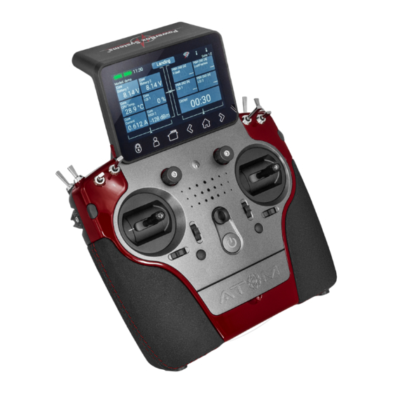
- Page 1 MANUAL 06/2022 V 3.oo At m www.powerbox-systems.com...
- Page 2 Dear PowerBox-Pilot, ATOM radio control system establishes a new standard in the market segment of upper mid-range systems. Based on the considerable expertise we have gained from the CORE, together with new developments in electronics, revised software, a smal- ler Linux computer and a revision to the method of case manufacture, we have been able to create a system which has few rivals in terms of price : performance ratio.
-
Page 3: Table Of Contents
5.1 Atom ........50... -
Page 4: Connections, Controls
1. Connections, controls 8 Toggle switches Quick-select buttons Optional stick switch Loudspeaker 4 proportional controls On / Off switch 4 digital trims 4 push-buttons Quick-select buttons Servo History History Screen Userdefined Home monitor back unock menu screen forward PowerBox-Systems − World Leaders in RC Power Supply Systems... -
Page 5: First Steps
These fields are known as widgets. NOTE The ATOM is fitted with a fully redundant power supply system, which is deliberately kept separate from the Linux computer and the other processors. This means than any malfunctions in the complex Linux system cannot possibly result in the transmitter switching itself off. - Page 6 Update process. Aerial symbols The aerial symbols illustrate in graphic form the LQI value of the Atom’s aerials, i.e., it corresponds to the reception quality of the return channel. PowerBox-Systems − World Leaders in RC Power Supply Systems...
-
Page 7: Menu
Servo Monitor Modell 3. MENÜ 3. Menü - Modellübersicht 3. MENÜ - Laden, kopieren oder löschen Functions von Modellen - Function overview Funktionen Mischer Virtual switches Mixer Flight Modes - Create or erase Flight Modes Empfänger Verwaltung - Funktionenübersicht Funktionen Mischer - Funktionen anlegen oder löschen - Empfängerübersicht... -
Page 8: Screen
Teacher / Student system. These two protocols can be generated by the receivers used by virtually all radio control systems. This allows the Atom’s Teacher / Student system to be very flexible in operation, even in conjunction with low-cost Student transmitters made by a variety of manufacturers. -
Page 9: Audio
• Intro The Intro Video setting enables you to switch the brief ATOM logo sequence on or off when the system is switched on. Disa- bling it shortens the initial boot time by a few seconds. -
Page 10: Model Menu
All passwords are stored in encoded form in the transmitter’s Linux computer memory, and cannot be read out. The purpose of the Forget button is to erase this information. At the bottom right you will find two input fields for the Portal login. - Page 11 Back in the Assignment screen it is also possible to rename the functions to suit your own preference. If you decide to assign the wing flaps at this point, you will learn to appreciate one of the truly unique features of the ATOM. As with the ailerons, you again assign a transmitter control to the flaps.
-
Page 12: Function Menu
button, amongst the quick-select buttons at the Back to our Wing screen: when all the assignments are complete, press the bottom in order to return to the overview. You can now continue assigning transmitter controls and servos to all the remaining Continue assigning transmitter controls and servos to all the remaining functions. -
Page 13: Setup
• Trim Mode You can choose any of four different trim modes. The stan- dard one is Offset mode: In this mode a trim adjustment affects the entire range of stick travel, i.e. including the end-points. Alternative trim modes are Left and Right; typically, these are intended for idle adjustment in the case of engines and turbines. -
Page 14: Hold / Failsafe
• Transmitter control Rate Here you can select a transmitter control which switches the rate on and off, or sets it to linear. The transmitter control can be any of the primary sticks, proportional controls or switches. • Rate The purpose of the Rate button is to adjust the travel of the transmitter... -
Page 15: Servo
3.3.6 Servo Here you will find the assigned servos again. Up to eight servos can be assigned to each function. As already mentioned in the Assistant, the travel and end-points of each servo can be adjusted separately here. Any adjustments you make to a servo at this point have no influence on the settings of the same servo if it is also assigned to another function. - Page 16 This is the procedure: use the arrow buttons to select the point you wish to adjust. Briefly press the displayed setting at Value, Smooth button then adjust the servo for this position. The can be used to even out the course of the curve. Right at the bottom Reset button you will find a which sets the curve back to a straight line.
-
Page 17: Binding A Receiver
You can only re-start the process if you first disconnect the power supply. • Option 2 Bind button on your ATOM, then connect the receiver to a power supply. The LED switches to continuous green Press the once the receiver is bound. -
Page 18: Selecting Atom/M-Link
These settings are usually accessed using a Telemetry widget, but are also available if you press the receiver image in the Bind menu. 3.4.4. Selecting ATOM/M-Link Multi- If your transmitter is equipped with a supplementary plex M-Link... - Page 19 – servos The next step is to select the which the differential travel is to affect: – Diff. Value Now briefly press the button under in order to set the percentage value, or to assign a transmitter control for adjusting the value. As the screenshot shows, you can also see any Expo values which you have already set.. •...
-
Page 20: Virtual Switches
CAUTION Do not assign this function to a trim which is already associated with one of the primary functions! In the overview you will now see the relative percentage travels of the servo outputs. 3.6 Virtual Switches The virtual switches can be used to digitize linear transmitter controls by setting up a switching threshold to generate a switched state. - Page 21 or Off. This is necessary, for example, if you only wish to assign a switching A further alternative is to define a fixed value - threshold to one linear control. In this case select one transmitter control as fixed value, and define a linear control for the other transmitter control.
-
Page 22: Servo Cut-Off
3.7 Servo Cut-OFF This feature provides a very easy means of switching a servo output to a fixed, previously defined value. An example of this might Servo Cut- be a motor arming switch, or a fixed, pre-defined nosewheel position when the undercarriage is retracted. Select the menu, then press in order to create a new cut-off function. -
Page 23: Telemetry Control
3.8 Telemetry Control The telemetry controls exploit the potential performance of Atom telemetry to the full. They enable you to use any of the telemetry values to control functions in the model. Since Atom telemetry operates virtually in real time, it would be possible, for example, to control motor power in relation to speed within certain limits. -
Page 24: Source
In this example the PBS-V60 voltage sensor is to be used to reduce motor power if the voltage of the flight battery falls to a dangerous level. You can rename the telemetry control under Name field. Now locate the field under Output showing the percentage value and briefly press it in order to set all the parameters. -
Page 25: Limiter
3.8.2. Limiter Here you enter the numerical range within which the telemetry function is to operate. The lower limit defines the telemetry value corresponding to -100% of the function. The upper limit defines +100% of the telemetry control. In our example the system starts to reduce motor power in the range 11.0V to 10.0V. -
Page 26: Flightmodes
Flight modes, also known as flight phases, are one of the ATOM’s most powerful features, but they are still easy to use! You can imagine a flight mode as a copy of a particular model memory, but one with slightly altered settings. - Page 27 Before you set up flight modes it is worthwhile considering which flight modes are important, and which are of secondary importan- To create a flight mode, press briefly on one of the boxes labelled “Standard”, and you will see the following screen display: You can immediately assign an informative name to the new flight mode by briefly pressing the left-hand field.
-
Page 28: Speech Output
TTS system available; the item which is included in the ATOM as standard. For each lan- guage several male and female voices are available. Due to the file size these are gradually loaded into the transmitter by means of updates. -
Page 29: Value
• Text At the Text option you can enter any text, which is then spoken by the TTS system, for example, by a switch. • Telemetry short The selected telemetry value is spoken together with its unit. The message can be triggered by switch activation, at regular intervals, or by a change in the value. -
Page 30: Replay
If you keep the button pressed, you can change the voice in this menu. First you will see the voices which are available for your set language. Pressing on the globe at bottom right displays all the voices together with the associated language. This enables ATOM you, for example, to have English expressions spoken using an English voice, even though the is set to German. -
Page 31: Vario
3.11 Vario ATOM Vario offers a number of options for fine-tuning the sound output relating to your model’s climb and sink. • Sensor The vario must be connected to a bound receiver, and must be visible in the Sensor List; a brief press on the Sensor button displays all the available sensors. -
Page 32: Door Sequencer
3.12 Door Sequencer ATOM door sequencer allows you to create two entirely independent sequences, which are activated with a switch. The sequencer includes a special feature in the form of a Pause function. For example, if you use a three-position switch, the sequence can be paused by moving the switch to the center position. - Page 33 • Loop Mode The sequencer runs as long as you keep the switch in the Active position. As soon as you move the switch to the Off position, the sequence - once started - runs through to the end, and then stops. Now select all the servos which are to be included in the sequence;...
- Page 34 As you can see in the above illustrations, as standard the sequencer simply runs from the Start point at -20% to the Stop point at +20%. To insert an additional point, press on the graph, then on Addition. Servo 10-Forward sequence.
-
Page 35: Mixer
NOTE A further interesting application for the sequencer would be any kind of brake flaps, spoilers or landing flaps. You know what happens: the spoiler retracts, and the servo buzzes a little because there is a slight residual mechanical resistance. Use the sequencer to move the spoilers slowly in the usual way, but set them to run past the retracted point by about 5%, then immediately back again;... -
Page 36: Curve Editor
3.13.1 Curve Editor The curve editor enables you to set up special mixing curves. • Points Select the number of points – up to a maximum of 33 points. • Select Point Use the arrow buttons to select the point you wish to adjust. The selected point turns green. -
Page 37: File Manager
3.15 File Manager The File Manager enables you to exchange files on the SD card in the ATOM transmitter with files stored on a USB memory stick. File types include model data, log files and also audio files for audible signals. -
Page 38: Teacher/Student System
Teacher transmitter, and is bound to the model. All functions, mixers and flight modes are set at the Atom transmitter. The only requirement on the Student transmitter is that it must generate all the desired functions on a sing- le channel. - Page 39 Student transmitter: press the empty field under External channel and move the appropriate stick or switch at the Student transmitter. The Atom automatically detects which channel has been moved, and assigns this channel to the transmitter control at the Atom. In use...
-
Page 40: Buttons
Technical information: P²-BUS The PowerBox Atom telemetry system and the are designed in such a way that each sensor supplies its own informa- tion, including sensor name, unit, number of sensor values, decimal point, priority and other data. A new sensor designed for use P²-BUS... -
Page 41: Size
4.1.1. Size With these three buttons you can adjust the size of the widgets: Small, Medium and Large. 4.1.2. Delete Widget You can delete the widget with this button. 4.1.3. Rescan Sensors You will need this function if you connect new sensors when the system is already running. The process gathers all sensor infor- mation on the P²-BUS. -
Page 42: Sensor
When one or more sensors is selected - as shown above - ad- ditional functions are displayed. 4.1.5. Sensor Sensor f you briefly press one of the values in the column, you can place a different value at this point. Keep your finger on a sensor name, and the following display appears: In this menu you can change the sensor name, and see the current sensor Address. -
Page 43: Adress
• You can now display the current address by keeping your finger on the sensor name, as explained above. This is purely for information, as the ATOM automatically manages the ad- PBS-V60 dressing. The standard address 41 of the is shown on the left of the picture. -
Page 44: Value
4.1.8. Value In the column below Value, you will see the name of the sensor value. If you press the name briefly, the screen will display all available values generated by the sensor. If you keep your finger on the button, a new window appears which displays the name and the current address of the sensor value. -
Page 45: Erase
Once you have entered all the settings, press at the bottom of the screen. 4.2 Timer ATOM permits you to use eight different, independent timers. For each timer it is possible to set a maximum of six different alarm sounds or spoken messages. -
Page 46: Start And Stop Time
4.2.2. Start and Stop time Start Stop The next step is to enter the times: if the Start time is greater than the Stop time, then the timer counts down; if the Stop time is greater than the Start time, it counts up. 4.2.3 Transmitter control for Start / Stop / Reset empty field under Start. -
Page 47: Auto Reset
4.2.4. Auto Reset If Auto Reset is set to On, then the timer will be reset to the starting time when the model is loaded, or when the transmitter is re-started. If Auto Reset is set to Off, the timer value at the time the transmitter is switched off is stored by the transmitter in the associated model file. -
Page 48: Servo Display
NOTE If you select Speech, then the interval time must be at least three seconds. If you want a faster spoken message, select Short Speech. Press to confirm your selections. If you want to set up additional audio outputs for this timer, press again. -
Page 49: Quick Select Menu
To freeze the widgets again simply wait a few seconds, or press HOME button. 4.7 Minimum and Maximum display Another important feature relating to telemetry data: the ATOM automatically records the maximum and minimum values for the incoming data. You can display these values very easily simply by double-pressing the widget:... -
Page 50: Update
Insert a USB stick in your PC, and follow the on-screen instructions. The USB stick will now be formatted, and all the essential data copied onto it. Once that is finished, switch your ATOM transmitter on and wait until it has booted up. Now insert the USB stick in the ATOM transmitter, move to the Settings >... -
Page 51: Wifi Update
5.1.2. Wifi Update The essential preparation is to set up the WiFi system as described under Point 3.1.4 Access to your router or mobile hotspot must be present. The rest of the process operates automatically. If you press Update and a connection to your WiFi exists, all the necessary files will be downloaded from the web and installed. -
Page 52: Receiver
5.2 Receiver All PBR receivers (except the PBR-8E) can be updated from the transmitter, provided that they are already bound to it. For this to System -> Software -> Check menu. work you must first switch on the model, i.e. the bound receiver. Now navigate to the Briefly press Update for one of the bound receivers. -
Page 53: Charging The Transmitter
6. Charging the transmitter If you wish to charge the ATOM, the first step is to open the front cover. Locate the two plugs attached to the mains PSU, and insert either one into the charge socket. If the battery symbol is displayed large and flashing on the screen, this means that you have a reserve for about 20 –... -
Page 54: Mechanical Transmitter Controls
• Opening the transmitter As standard the ATOM is supplied in the correct mode, as specified by the customer, but some users may find that the centring spring tension or the ratchet function needs to be adjusted to meet their personal preferences. The first step is to remove the handrests. - Page 55 • Adjusting the tension of the primary stick centering springs On the screws 1 and 2, the centering spring tension can be adjusted for the respective axis. Tightening the screw further increases the spring tension. If you find it impossible to set your preferred spring tension, we can supply a range of stronger springs.
-
Page 56: Calibrating The Transmitter Controls
• Adjusting the throttle travel The travel of the throttle stick on the ATOM is adjustable. This is useful for 3D pilots in particular, as it enables them to set a me- chanical limit on throttle travel. Adjustment is carried out by tightening screws 5. The throttle travel can also be set up asymme- trically. -
Page 57: Specifications
• main adapter • conversion tool • sticker set • screen cleaning cloth • exclusive Shirt „ATOM“ • Instruction manual in German and English RECEIVERS 12. Atom accessories PBR-9D PBR-5S Order No. 8230 Order No. 8210 This is a nine-channel receiver with two This is a five-channel receiver with a single receiver circuit. -
Page 58: Service Note
For this reason, we accept no liability for loss, damage or costs which arise due to the use or operation of the PowerBox ATOM, or which are connected with such use in any way. -
Page 59: Fcc
Cet appareil est conforme aux exigences d'exposition aux RF pour les appareils portables. L'appareil est destiné à être utilisé à la main, les antennes de l'émetteur étant maintenues à plus de 60 mm des mains et à plus de 20 cm du corps en utilisation norma- PowerBox ATOM! We wish you every success with your new Donauwörth, June 2022... - Page 60 06/2022 PowerBox-Systems GmbH Ludwig-Auer-Straße 5 86609 Donauwörth Germany +49-906-99 99 9-200 +49-906-99 99 9-209 www.powerbox-systems.com...
Need help?
Do you have a question about the ATOM and is the answer not in the manual?
Questions and answers