
Subscribe to Our Youtube Channel
Summary of Contents for Bendix CVS SmarTire Trailer-Link
- Page 1 SmarTire Trailer-Link TPMS ™ Tire Pressure Monitoring System Operator’s Manual This booklet contains important operational and safety information that benefits you and subsequent owners.
- Page 2 Sources of Additional Information about your SmarTire ® ™ System by Bendix Consult the vehicle manufacturer’s documentation. Visit www.bendix.com for free downloads of these publications from the Literature Center at www.bendix.com. BW2799 SmarTire Tire Pressure Monitoring System (TPMS) Operator’s Manual BW2809 SmarTire TPMS Hand Tool Manual BW2820 SmarTire Low Frequency (LF) Tool Users Manual BS2822 SmarTire TPMS Walk Around Card...
- Page 3 3.6 Tire Sensor Specifications Section C: System Installation – Components and Programming 4 0 Installing The SmarTire Trailer-Link System 4.1 Configuring & Customizing Your SmarTire Trailer-Link System 4 2 SmarTire Trailer-Link Axle CIP Adjustment Instructions Section D: SmarTire Trailer-Link Display Options...
- Page 4 GENERAL SAFETY GUIDELINES WARNING! PLEASE READ AND FOLLOW THESE INSTRUCTIONS TO AVOID PERSONAL INJURY OR DEATH: When working on or around a vehicle, the following guidelines should be observed AT ALL TIMES: ▲ Park the vehicle on a level surface, apply the parking brakes and always block the wheels.
-
Page 5: System Features
There are three types of tire alerts: Pressure Deviation Alert, Critical Low Pressure Alert, and High Temperature Alert; ● The SmarTire Trailer-Link system data can be sent through the tractor’s J1939 communication network via the tractor-mounted SmarTire TPMS for seamless vehicle integration; and ●... - Page 6 200.0216). Additionally, for tractors equipped with ECU part number 200.0184, in order for the ECU to be able to communicate with the SmarTire Trailer-Link ECU, the ECU firmware MUST BE updated to new firmware. For instructions on performing this update, please contact your Bendix account manager...
-
Page 7: Section A - System Overview
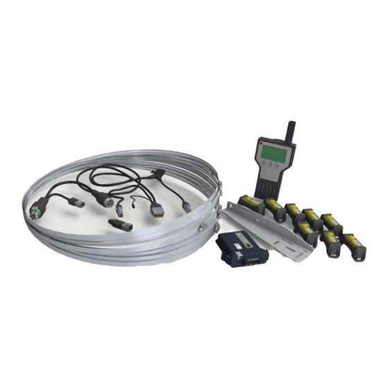
Sensor Straps. Sensors are mounted to the surface of the rim using a stainless steel strap, a reliable and universal method of sensor installation. Harness. Designed to not require a separate power supply, the harness supplies trailer ABS system power to the SmarTire Trailer-Link Tire Pressure Monitoring System ECU. 1.2 Maintenance Tool Maintaining tires in the yard is just as important as real-time tire information for the driver, but many TPMS systems don’t include functionality to help... - Page 8 Industrially-designed for the rugged requirements of a commercial trailer chassis, the SmarTire Trailer-Link ECU can monitor up to eight (8) wheel positions when linked with a tractor with SmarTire TPMS, and more when applied as a stand alone trailer TPMS. The total number of tires monitored on both the tractor and trailer cannot exceed twenty.
- Page 9 1.4 Fundamentally, Why Is Temperature Monitoring Important? The Pressure/Temperature Relationship Tire manufacturers specify that tire pressures should be checked and adjusted when a tire is “cold”, but most people may not know why, or even what a “cold tire” is. The temperature of a tire actually has a significant impact on its inflation pressure.
- Page 10 The charts below illustrate the equivalent inflation values for a series of Cold Inflation Pressures (CIPs) at various temperatures. The temperature values represent the temperature of the air contained inside the tire. This temperature can be estimated for a cold tire using the outside, ambient temperature. Chart 1 Chart 2 The charts above are to be used as a guide only.
- Page 11 “Temperature Compensated” pressure deviation values and alerts. By measuring the operating temperature of a tire and comparing it to the CIP value programmed into the system, the SmarTire Trailer-Link system will know what a tire’s pressure is supposed to be in relation to its operating temperature.
-
Page 12: Tire Maintenance
The advantages of temperature compensation are even more dramatic when a tire has a slow leak. A tire that is constantly losing pressure will not be able to reach thermal equilibrium because the contained air simply cannot expand enough to generate the required pressure, regardless of how hot the tire becomes. - Page 13 IMPORTANT READ THESE INSTRUCTIONS PRIOR TO INSTALLATION ™ This SmartTire Trailer-Link TPMS kit is pre-programmed and ready to use, subject to your application: ● The sensors have been PRE-ASSIGNED TO WHEEL POSITIONS and are identified on each unit with a position label (P1, P2, P3, etc.) – install the sensors as shown in Figure 1.
-
Page 14: Section B - System Installation - Tire Sensors
Section B - System Installation – Tire Sensors 3.0 System Installation: Tire Sensors 3.1 Sensor Overview ® The SmarTire TPMS sensor monitors tire pressure and temperature every twelve (12) seconds and transmits tire data every three (3) to five (5) minutes. If a pressure change of 3 PSI is detected, the sensor will not wait for the next regular transmission and will transmit tire data immediately. - Page 15 Tire changing equipment Tire balancing equipment 3.3 Tire Sensor Installation Remove the wheel from the vehicle and then remove the tire. Wrap the strap around the rim in the lowest point of the drop center well and mark it 1” (2.5 cm) past the worm gear. Cut the strap at the mark. Excess strap MUST be removed or it will break-off and damage the tire.
- Page 16 3.4 Re-mounting Tires After A Sensor Has Been Installed Please read this section carefully and follow each step precisely to ensure you do not damage the sensor when mounting the tire. If steps are not taken to avoid the sensor located in the drop center well of the rim, it can be damaged by tire beads as the tire is mounted.
- Page 17 3.4.2 Re-Mounting Tires Using Tire Irons To avoid damaging the sensor, simply mount the tire ensuring that the last part of the bead to slip over the flange happens directly at the sensor. Start at one end of the tire and work towards the opposite end with the tire oriented so that the beads are first pushed under the rim flange directly opposite the sensor (1) and then worked over the flange toward the sensor (2).
- Page 18 3.4.3 Re-Mounting Commercial Tires Using a Vertical Tire Machine Place the rim on the machine so that the rim flange clamp is at the 12 o’clock position, the sensor is at the 2 o’clock position and the mounting hook is at the 8 o’clock position. Rim Flange Clamp Sensor Figure 8...
- Page 19 Place the tire on the rim with the bottom bead under the flange at the 6 o’clock position with the mounting shoe at the 9 o’clock position. Advance the mounting shoe clockwise to pass the lower bead over the rim flange. Return the mounting shoe to the 9 o’clock position, depress the upper bead under the rim flange at the 6 o’clock position and advance the mounting shoe clockwise until the second bead is completely mounted.
- Page 20 Advance the turn-table clockwise using the mount head to guide the rest of the bottom bead over the flange and on to the rim. When assembled correctly, the bead will slip over the flange without contacting the sensor. Repeat for the top bead. Do not allow the pinch point to slip as the rim rotates or the sensor could be broken.
- Page 21 3.5.2 Using a Tire Mounting Machine After removing the deflated tire / wheel assembly from the vehicle, unseat the beads directly opposite the sensor and valve stem. The sensor should be located at the valve stem (the rim mounted decal should also indicate the sensor’s location).
- Page 22 3.6 Tire Sensor Specifications Tire Sensor (with cradle) Power Internal Lithium Battery Weight 1.89 oz (58.7 g) Dimensions 3.58 x 1.65 x 1.34 in. (91 x 42 x 34 mm) Operating Temperature -40º F to 257º F (-40º C to 125º C) Pressure Accuracy at 0ºC +/- 2.39 PSI (0.65 bar) to 50º...
-
Page 23: Section C: System Installation - Components And Programming
Where the lines intersect is the approximate mounting location of the provided SmarTire Trailer-Link bracket and ECU. For a single axle trailer, place the ECU slightly in front of the axle. - Page 24 Packard Recpt Packard plug Packard Plug Packard Recpt P3 - ABS Power Splice Connection Detail A-A P3 PIN# Designation Color Brake Light Pwr. White IGN. Power Ground Black ™ Figure 16 - SmarTire Trailer-Link TPMS ABS Power Splice (Part No: K075867)
- Page 25 Step 6. After installing the ABS Power Splice harness, connect the 3-pin ™ power connector, (P3 in Figure 16) to the SmarTire Trailer-Link TPMS Wiring Harness, (P3 in Figure 17). Then route the harness along the underside of the trailer, taking care to avoid any slider mounts and suspension components.
- Page 26 In some cases, the supplied 6ft harness may not be sufficient for your ™ installation. If this is the case, there is an optional 15 ft SmarTire Trailer-Link TPMS Harness Part No: K075869 available. Please contact your distributor to order this part.
-
Page 27: Pre-Configured Settings
4.1 Configuring & Customizing Your SmarTire Trailer-Link ™ System During the installation process, the default settings for SmarTire Trailer-Link ™ TPMS should be customized to the trailer by the installer. Using the SmarTire ® ® Trailer-Link Diagnostics Software within Bendix ACom Diagnostics 6.6 (or... - Page 28 Power up the SmarTire Trailer-Link ECU. In most cases the trailer will need to be connected to a tractor in order to receive power. The diagnostic LED on the SmarTire Trailer-Link harness can be viewed at power up to ensure that the ECU has power.
- Page 29 12. In the case of a programming error, the following screen is shown: Figure 25 If this occurs, ensure the SmarTire Trailer-Link ECU is powered and the connection from the tool to the SmarTire Trailer-Link harness is correct. Press the Check...
- Page 30 4.2.3 Trailer Sensor ID Walk-Around Learn Procedure ™ The following steps are only to be used for the SmarTire Trailer-Link ECU. When the tires are rotated or replaced on a trailer equipped with a SmarTire tire pressure monitoring system, the trailer TPMS module must be taught the new position of each sensor ID code.
- Page 31 TPMS Maintenance Hand Tool, go to the first tire to ® Using the SmarTire be programmed and proceed to activate each of the trailer’s tire pressure sensors in the proper order. Starting on the left side (road side) of the trailer at the forward axle, begin by activating the inner tire and proceed to work counterclockwise from inner to outer tire.
- Page 32 11. After the last tire position has been learned into the tool, press the Down arrow button. The tool is now ready to transmit this information to the ™ SmarTire Trailer-Link receiver. Figure 34 12. Using the SmarTire Trailer-Link programming cable (Part Number K092501), connect the tool to the SmarTire Trailer-Link harness.
- Page 33 ™ 15. If this occurs, ensure the SmarTire Trailer-Link ECU is powered and the connection from the tool to the SmarTire Trailer-Link harness is correct. Press the Check button to retry the operation, press the Return button to return to the learn procedure screen in step 5, or press the button to abort the learn procedure and return to the main menu.
-
Page 34: Section D: Smartire Trailer-Link
‘T’ axles following the last tractor axle on the 2-inch SmarTire dash display. The dash gauge will reboot shortly after the wireless connection is established with the SmarTire Trailer-Link system and the new trailer axle positions will be displayed for the tractor. To become more familiar with the functions of the SmarTire dash display, refer to Section C of the SmarTire Operator’s Manual BW2799 before continuing on in this section. - Page 35 SmarTire Trailer-Link ECU. For example, if the tractor has its first level alert set to 10% -- but the SmarTire Trailer-Link ECU is configured for a 15% first level alert – the driver will see trailer tire alerts based on the 15% figure stored in the Trailer-link ECU.
- Page 36 Code (DTC) 1 min. TPMS sensors by using the Maintenance Hand tool 090.0011 and replace sensors if unresponsive ™ The SmarTire Trailer-Link ECU is not properly Setup 3x Blinks programmed and is unable to connect. Check Diagnostic & then...
-
Page 37: Section E: Additional Component Details
Preferred Mounting hardware: ¼ -20 (M6X1) Flange Head CAPSCREW, torque to 7-10 FT/LBS (13 Nm) ● The SmarTire Trailer-Link ECU has an internal antenna and should be mounted free of any metal (only half the enclosure should be covered by the chassis or metal bracket) - Page 38 4 7 in (119 5 mm) 5 28 in (134 mm) 1 43 in (36 4 mm) 4 0 in (102 mm) Figure 41 6.1.3 SmarTire Trailer-Link Module Connector Pin Description Position Signal RS232-TX NOT USED BRAKE LIGHT-L NOT USED...
- Page 39 6.1.4 SmarTire Trailer-Link TPMS Diagnostics ™ Interface Harness Part No: K071016 Detail A-A 72 Inch 10 Inch Detail C-C Back View Detail B-B DTM04-4P Figure 43...
- Page 40 6.1.5 SmarTire Trailer-Link Mounting Bracket ™ Part No: K092801 (dimensions in inches) 1 2 in 12 in 3 in Figure 44...
-
Page 41: Section F: Troubleshooting
How can the SmarTire Trailer-Link module be diagnosed further? A: In the event that the SmarTire Trailer-Link ECU does not connect with the SmarTire vehicle-mounted TPMS system, follow these steps: Check to make sure the SmarTire Trailer-Link ECU and vehicle-mounted TPMS ECU power up during start up. - Page 42 A: After the wireless link between the tractor SmarTire TPMS ECU and ™ the SmarTire Trailer-Link module has been established and the gauge has rebooted, trailer tire sensor data will be displayed within five (5) to eight (8) minutes on the gauge.
- Page 43 7.1.3 Q: When the Gauge first powers up, the alert lamp is blinking and a triangle with an exclamation mark is displayed. A few minutes later the alert clears and the display returns to normal. Was there an alert? A: During the start up sequence, the Gauge may clear itself of a previous alert condition or issue a momentary alert if a tire sensor has not reported in.
- Page 44 7.1.4 Q: What additional diagnostic information is available? A: The external LED part # K075866 is connected via the cable harness as a separate plug. Please refer to Section C, 4.0, step 7 for details on installation and location of this LED. The LED functions as described in the table below. Flashing with pattern will have periods of 0.3 second on and 0.3 second off repeating every 6 seconds.
- Page 45 Notes for Table 5 Note 1: This Diagnostic Trouble Code (DTC) occurs when the SmarTire ™ Trailer-Link ECU has not received information from a tire sensor for 35 minutes. Possible causes are: A tire has been replaced and a tire sensor is no longer in range of the ECU and is therefore no longer being received.
- Page 46 A: Wheel assemblies may have been relocated/rotated on the trailer without ™ the SmarTire Trailer-Link ECU having been updated. To correct this, follow ® the steps in Section C, 4.2.3 in combination with the SmarTire TPMS Maintenance Hand tool to relearn sensors into their correct tire positions.
- Page 47 it may simply be pressed into a new cradle for reuse. Avoid reusing the strap – worm gear could be damaged internally. If points a. and b. did not yield any results, the sensor is either missing or has been damaged. Remove the wheel carefully and inspect the inside tire lining for any damage if the sensor, strap, and cradle are found to have been damaged and non-operational.
-
Page 48: Appendix 1: Replacement Parts
® SmarTire TPMS Maintenance Tool Kit 090.0011 SmarTire LF Tool 090.0021 Tire Sensor with Cradle 201.0007 201.0007N 6 ft SmarTire Trailer-Link TPMS Harness K075868 K095615 15 ft SmarTire Trailer-Link TPMS Harness K075869 K095616 SmarTire Trailer-Link TPMS Diagnostics Interface K092501 Harness... -
Page 49: Appendix 2: System Scope Of Use & Alerts
Appendix 2: System Scope Of Use & Alerts 9.0 System Scope Of Use And Alerts This tire monitoring system does not in any way replace the need for regular maintenance of the tire pressures and visual inspection of tires for damages. 9.1 System Installation And Usage ®... -
Page 50: Federal Communications Commission (Fcc) Notice
9.4 Federal Communications Commission (FCC) Notice This device complies with part 15 of the FCC rules. Operation is subject to the following two conditions: This device may not cause harmful interference, and This device must accept any interference received, including interference that may cause undesired operation. - Page 52 Log-on and Learn from the Best On-line training that's available when you are 24/7/365. Visit www.brake-school.com. SEE PAGE 2 FOR A LIST OF FURTHER SOURCES OF INFORMATION. BW2920 © 2014 Bendix Commercial Vehicle Systems LLC, a member of the Knorr-Bremse Group. All Rights Reserved. 08/13...
Need help?
Do you have a question about the SmarTire Trailer-Link and is the answer not in the manual?
Questions and answers